1-Nitronaphthalene, a non-OD, non-MDO polytype
-
Matthias Schöbinger


Abstract
Crystals of 1-nitronaphthalene were grown by evaporation of a methanol solution. The structure [P21/c, a = 13.2780(13) Å, b = 3.8131(3)° Å, c = 31.851(3) Å, β = 91.173(8), V = 1,612.3 Å3] was solved from a crystal twinned by twofold rotation about [100]. Twinning is explained by the polytype character: layers with (idealized) p2111 symmetry can connect via either 1‾ or 21 operations, leading to geometrically distinct pairs of layers. In the twin individuals, the two kinds of contacts alternate, at the composition plane two subsequent contacts of the same type are realized.
1 Introduction
Performing a literature search on the crystal chemistry of nitrated polycyclic aromatics, we were surprised that no crystal structure of 1-nitronaphthalene has been deposited in the Chemical Structure Database (CSD). 1 Apparently, only a few co-crystals have been successfully structurally characterized so far. 1-Nitronaphthalene is a common chemical and we would have expected at least unintentional crystallization from reaction mixtures, leading to an opportunistic crystal structure determination.
Since crystalline commercial 1-nitronaphthalene was available on-site, we decided to investigate the matter. A few preliminary diffraction experiments of the commercial material solved the riddle of the lack of structural data: intensities were invariably diffuse and weak making indexation difficult. Therefore, we recrystallized a small amount from methanol, growing long (>1 cm) needle-shaped crystals. Here likewise, large crystals featured subpar diffraction patterns plagued by systematic twinning and pronounced mosaicity. However, by collecting data of a rather small crystal on a modern diffractometer system with large detector distance and fine slicing, we were able to satisfactorily solve and refine the structure from a twinned crystal.
From a crystallographic point of view, 1-nitronaphthalene piqued our interest owing to its polytypism (the ability of layer structures being arranged in different ways). Polytypes can be classified into OD polytypes and non-OD polytypes. OD originally stands for order-disorder, though the name is unfortunate, since OD polytypism is unrelated to order-disorder phase transformations. In OD polytypes, for which a comprehensive and very useful theory has been developed, 2 the different ways of connecting layers are geometrically equivalent. This means that there are an infinity of possible polytypes, which are all locally equivalent. The set of these polytypes is called an OD family. In contrast, in the case of non-OD polytypes, the layers of members of a polytype family can connect in geometrically different ways.
1-nitronaphthalene is of the rarer non-OD type. We will show how to apply the formalism developed in the context of OD theory also in such a case and thus demonstrate its generality.
2 Experimental
2.1 Crystallization
Needles of 1-nitronaphthalene were grown by dissolving 100 mg of commercial material (Fluka, purum) in 10 ml methanol followed by evaporation of the solvent at room temperature over night.
2.2 Data collection and refinement
Multiple crystals were selected under a polarizing microscope and checked for diffraction quality using CuKα radiation on an STOE StadiVari diffractometer system equipped with a Dectris Eiger CdTe hybrid photon counting detector. Crystals were systematically twinned with a high degree of reflection overlap and featured pronounced mosaicity. Generally, small crystals were of better diffraction quality. Intensity data of the crystal with the least mosaicity were then collected at 200 K in a dry stream of nitrogen up to 2θ = 140° using fine-sliced (0.3°) ω-scans.
Data were processed with X-Area. 3 Two domains were identified and integrated concurrently using overlap information (HKLF5 format). Periodic refinement of the orientation matrix from reflection positions had to be turned off for reliable results. This proved to be a non-issue owing to the stability of the goniometer. A correction for absorption and beam inhomogeneity was applied using the multi-scan approach implemented in LANA. 3
The structure was solved using the dual-space approach implemented in SHELXT 4 and refined against F2 using SHELXL. 5 C, N and O atoms were refined using anisotropic atomic displacement parameters (ADPs). H atoms were placed at calculated positions and refined as riding on the parent C atom. More data collection and refinement details are collected in Table 1.
Data collection and structure refinement details.
| 1-nitronaphthalene | |
|---|---|
| Crystal data | |
| Formula | C10H7NO2 |
| M r | 173.17 |
| Temperature (K) | 200 |
| Crystal system, space group | Monoclinic, P21/c |
| a, b, c (Å) | 13.2780(13), 3.8131(3), 31.851(3) |
| β (°) | 91.173(8) |
| V (Å3) | 1612.3(3) |
| Z | 8 |
| Radiation type | CuKα‾ |
| μ (mm−1) | 0.836 |
| Crystal shape | Rod |
| Crystal size (mm) | 0.13 × 0.04 × 0.02 |
| Data collection | |
| Diffractometer | STOE StadiVari |
| Absorption correction | Multi-scan (LANA) |
| Tmin, Tmax | 0.694, 0.962 |
| No. of measured, independent and observed [I > 2σ(I)] reflections | 26214, 14623, 9524 |
| R int | 0.0417 |
| Refinement | |
| (sin θ/λ)max (Å−1) | 0.61 |
| R[F2 > 2σ(F2)], wR(F2) | 0.0736, 0.2558 |
| S | 1.073 |
| Δρmax, Δρmin (e Å−3) | 0.260, −0.301 |
| Twin operation | Twofold rotation about [100] |
| Twin volume ratio | 0.599:0.401(3) |
| CSD number | 2358669 |
3 Results and discussion
3.1 Crystal and molecular structure
1-Nitronaphthalene crystallizes in a space group of type P21/c with Z′ = 2 molecules in the asymmetric unit. The crystallographically independent molecules are indicated by different shading in Figure 1. The atoms in both molecules are labeled equivalently up to an added A or B letter. The molecules are accordingly called the A and B molecule, respectively.
![Figure 1:
The crystal structure of 1-nitronaphthalene viewed along [010]. C (gray), N (blue) and O (red) atoms are represented by ellipsoids drawn at the 75 % probability levels, H atoms by white spheres of arbitrary radius (0.2 Å). The crystallographically distinct A (light) and B (dark) molecules are differentiated by brightness. Symmetry elements of the P21/c space group are indicated using the usual graphical symbols.
6](/document/doi/10.1515/zkri-2024-0089/asset/graphic/j_zkri-2024-0089_fig_001.jpg)
The crystal structure of 1-nitronaphthalene viewed along [010]. C (gray), N (blue) and O (red) atoms are represented by ellipsoids drawn at the 75 % probability levels, H atoms by white spheres of arbitrary radius (0.2 Å). The crystallographically distinct A (light) and B (dark) molecules are differentiated by brightness. Symmetry elements of the P21/c space group are indicated using the usual graphical symbols. 6
The molecules are arranged in layers extending parallel to (001), which are called L n , where n is a sequential number (Figure 1). Adjacent layers L n and Ln+1 are alternately related by the 1‾ and [−21−] operations of the P21/c space group. Note: For symmetry operations with a directional element, we use a notation with places to indicate the direction (e.g. [− − 21] is a screw rotation in the [001] direction, etc.). 7 Layers L n and Ln+2 are mapped by c-glides reflections, which arise from a combination of the [−21−] and 1‾ operations. Four layers form a translation period in the [001] direction.
The two distinct molecules are geometrically practically equivalent (see below for quantification). The nitro group is tilted with respect to the naphthalene ring system (Figure 2), owing to steric interaction with C9’s hydrogen atom. The torsion angle between the respective least squares planes is 40.1(6)° and 38.1(6)° for the A and B molecule, respectively.
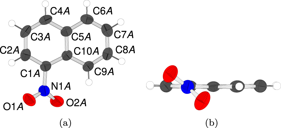
The A molecule (a) projected on the plane of the naphthalene system and (b) viewed along the bond connecting the nitro group the naphthalene moiety. Atoms as in Figure 1. The B molecule is geometrically practically equivalent and therefore not shown.
3.2 Pseudo-symmetry of layers
Our argument that the crystal structure of 1-nitronaphthalene possesses polytype character is based on the pseudo-symmetry of the L n layers. In fact, the layers can be considered as having (pseudo) p2111 symmetry (see Figure 3). According to the International Tables of Crystallography, the lower case Bravais symbol indicates the two-dimensionality of the translation lattice and it is implicitly assumed that the layer extends in the (001) plane. 8 The A and B molecules, which are distinct according to the space group symmetry, are related by pseudo-[21 − −] screw rotations.
![Figure 3:
L
n
layer in 1-nitronaphthalene projected on the layer plane (001). Atoms as in Figure 1. The locations of the pseudo [21 − −] axes are represented by the usual symbols.](/document/doi/10.1515/zkri-2024-0089/asset/graphic/j_zkri-2024-0089_fig_003.jpg)
L n layer in 1-nitronaphthalene projected on the layer plane (001). Atoms as in Figure 1. The locations of the pseudo [21 − −] axes are represented by the usual symbols.
To prove the validity of our interpretation, it is crucial to quantify the deviation from this idealized symmetry. Thereto, the atom coordinates were transformed into a Cartesian coordinate system and the location of the screw axis determined by averaging the y and z coordinates of the C, N and O atoms. The intrinsic translation of the screw rotation was derived by halving the a basis vector. This, now well defined, screw rotation was then applied to the A molecule, to map it onto the B molecule. An overlay of the molecules is shown in Figure 2 and the distance between atoms is given in Table 2. A maximum distance of 0.233 Å for the C7A/C7B pair confirms the pseudo-symmetry and henceforth we will consider (slightly) idealized L n layers with p2111 symmetry. 8 The slight deviation is mostly due to a rotation about an axis parallel to [100], as seen in Figure 4(a).
Distance d between atoms of the image of the A-molecule by the [21 − −] layer symmetry to the atoms of the B-molecule.
| Atoms | d (Å) | Atoms | d (Å) |
|---|---|---|---|
| C1 | 0.087 | C8 | 0.177 |
| C2 | 0.144 | C9 | 0.109 |
| C4 | 0.153 | C10 | 0.027 |
| C4 | 0.155 | N1 | 0.166 |
| C5 | 0.097 | O1 | 0.211 |
| C6 | 0.185 | O2 | 0.218 |
| C7 | 0.233 |
![Figure 4:
Overlay of the image of the A-molecule by the pseudo-[21 − −] screw rotation (red) and the B-molecule (blue), viewed along (a) [100] and (b) [010].](/document/doi/10.1515/zkri-2024-0089/asset/graphic/j_zkri-2024-0089_fig_004.jpg)
Overlay of the image of the A-molecule by the pseudo-[21 − −] screw rotation (red) and the B-molecule (blue), viewed along (a) [100] and (b) [010].
3.3 Polytypism
According to the p2111 symmetry, 8 the L n layers are non-polar, which means that both sides are related by symmetry. However, in the crystal structure of 1-nitronaphthalene, both sides connect in non-equivalent ways to adjacent layers: by 1‾, resulting in (L n , Ln+1) pairs of layers with p1‾ layer symmetry, and by [−21−] resulting in pairs with p1211 symmetry. Since these pairs feature distinct symmetry, notably the orientation relation of the adjacent layers are different, they are geometrically different. The two distinct layer contacts will be designated according to the operations relating the adjacent layers as 1‾- and [−21−]-contact, respectively.
This proves the polytype character of 1-nitronaphthalene, since a layer can contact in different ways to adjacent layers. Moreover, it violates the vicinity condition of OD theory, 9 which states that equivalent sides of equivalent layers connect in such a way to adjacent layers that the resulting pairs are equivalent. 1-Nitronaphthalene is therefore a non-OD polytype. Note that the non-OD character stems from different sets of operations that relate layers of the same kind. An alternative way of achieving non-OD polytypes is a layer that can contact to two (or more) layers of different kind. If this leads to structures composed of distinct sets of layers, one also speaks of merotypes instead of polytypes. 7
In OD polytypes, layer contacts are equivalent and therefore it is reasonable to associate a ‘width’ or ‘thickness’ to layers. The vector perpendicular to the layer plane and of the length of one layer width is typically called c0 (for stacking direction [001]). In contrast, in non-OD polytypes, the distinct layer contacts may lead to structures with different density and there may therefore be a distinct c0 for each layer contact.
Interestingly, for 1-nitronaphthalene, the [21 − −] axis (see above for determination) of the layer symmetry is located a negligible 0.003 Å away from the
3.4 Comparison of layer contacts
Even if adjacent layers do not form equivalent pairs, it is sometimes possible to construe an OD interpretation by (formally) ‘cutting’ the molecules and considering the layer contact as a distinct OD layer with higher symmetry (see for example Ref 10).
To rule out such an interpretation and to show that the layer contacts are indeed chemically different, we performed a Hirshfeld surface analysis 11 using Crystal Explorer. 12 Figure 5 shows the Hirshfeld surface of both sides of an L n layer decorated with dnorm values. For the 1‾-contact, large dnorm values (red spots in Figure 5(a)) show that the most prominent inter-layer interactions are O3B–H8A contacts. In contrast, there are no such prominent interactions for the [−21−]-contact (Figure 5(b)).
![Figure 5:
Hirshfeld surfaces of an L
n
layer decorated with dnorm values for the (a) 1‾- and the (b) [−21−]-contact.](/document/doi/10.1515/zkri-2024-0089/asset/graphic/j_zkri-2024-0089_fig_005.jpg)
Hirshfeld surfaces of an L n layer decorated with dnorm values for the (a) 1‾- and the (b) [−21−]-contact.
While these results shouldn’t be over-interpreted, since Hirshfeld surfaces analyses are sensitive to small distortions, it shows that the contacts are chemically different and that the crucial contact is from the O atom of the nitro-group to an H atom in the adjacent layer.
To get a clearer picture of the different layer contacts, we applied the [−21−] screw rotation of the L n layer to a (Ln−1, L n ) pair of layers and overlaid it with the (L n , Ln+1) pair. The result is shown in Figure 6(a). As described above, the L n layer and its image overlap nearly perfectly. The overlay of the image of Ln−1 and Ln+1 quantifies the difference of the two contacts.
![Figure 6:
Comparison of the two kinds of layer contacts. (a) Overlay of an (L
n
, Ln+1) pair (red) and the image of the (Ln−1, L
n
) pair (blue) by the [21 − −] operation of the L
n
layer viewed along [010]. A dotted line represents the interface between the layers, short O1–H contacts are indicated by solid lines. (b) Overlay of the Ln+1 layer (red) and the image of the Ln−1 layer (blue) by the [21 − −] operation of the L
n
layer. H atoms are omitted for clarity.](/document/doi/10.1515/zkri-2024-0089/asset/graphic/j_zkri-2024-0089_fig_006.jpg)
Comparison of the two kinds of layer contacts. (a) Overlay of an (L n , Ln+1) pair (red) and the image of the (Ln−1, L n ) pair (blue) by the [21 − −] operation of the L n layer viewed along [010]. A dotted line represents the interface between the layers, short O1–H contacts are indicated by solid lines. (b) Overlay of the Ln+1 layer (red) and the image of the Ln−1 layer (blue) by the [21 − −] operation of the L n layer. H atoms are omitted for clarity.
First observe that, as noted above, the [001] components of the layer origins are virtually identical, which justifies the choice of a single c0 vector connecting the planes of adjacent layers. However, in the [100] direction, there is a small, but distinct difference in the origin shift. Apart from that, both layer contacts look very similar in the [010] projection. However, a projection along [001] (Figure 6(b)) reveals that their orientation is reflected with respect to [010], which follows from the fact that [−21−] retains, but 1‾ inverses the orientation with respect to [010].
This results in entirely different inter-layer O–H contacts. As noted above, at the 1‾-contact, two molecules ‘touch’ via short O1A–H3B contacts (2.55 Å, red lines in Figure 6(a)). The two connected molecules feature the same orientation with respect to [001] (the nitro group points in the same direction).
In the [−21−]-contact, on the other hand, the shortest inter-layer O–H contact is significantly longer (O1A–H8A, 2.70 Å, blue lines in Figure 6(a)). Here, the connected molecules are related by 1‾ and thus feature different orientation with respect to [001].
Ultimately, we note that the layer interfaces are chemically distinct and there are two ways of placing the Ln+1 layer into the mold of the L n layer’s interface. We see no reasonable way of forcing an OD interpretation in this case.
3.5 Application of the OD formalism
In the context of OD theory a rich formalism for analyzing OD polytypes has been developed, which can however also be applied to non-OD polytypes with small adaptations, as we will do in the upcoming sections.
3.5.1 NFZ relationship
The central point of OD theory is that, given a layer, distinct placements of adjacent layers can lead to geometrically equivalent layer pairs. Given the layer L
n
, the number of ways of placing the adjacent layer Ln+1 is called Z and is calculated using the NFZ relationship.
13
Since in 1-nitronaphthalene layers can contact in two non-equivalent ways, the NFZ relationship is applied to both separately. Accordingly, the number of ways of placing the adjacent layer will be called
To calculate Z, for each layer L
n
one has to determine the subgroup
Then, one needs to know the partial operations (POs, operations that apply for distinct layers, not the whole structure) relating the adjacent layers. These are obtained by forming the coset of the layer group of L
n
and a representative operation mapping L
n
onto Ln+1. We obtain, up to lattice translations,
In both layer contacts, there is a PO inverting the orientation of the layers with respect to the stacking direction (called σ-ρ-POs in the OD literature): [−21−] and 1‾, which are also symmetry operations of the resulting layer pairs. In such a case, the number of ways of placing the adjacent layer is obtained by coset decomposition of the subgroup
We conclude that not only is 1-nitronaphthalene of the non-OD type, but also both layer contacts do not possess OD character. Note however, that given a layer L
n
, the total number of ways of placing the adjacent Ln+1 layer is
A different situtation would arise if the [−21−] PO relating two layers would have an intrinsic translation of rb with
3.5.2 MDO polytypes
A further crucial concept is that of polytypes of a maximum degree of order (MDO). 14 The definition was originally given only for OD structures. However, it is just as useful in the non-OD case. In a family of polytypes, the MDO polytypes are those that cannot be decomposed into fragments of simpler polytypes. Here, there are two distinct kinds of pairs of layers (the 1‾- and [−21−]-contacts) and the MDO polytypes are those that consist of only one type of these pairs. MDO1 (all adjacent layers related by 1‾) has P21/c11 symmetry and MDO2 (all adjacent layers related by [−21−]) has P212121 symmetry. In both cases, there is one 1-nitronaphthalene molecule in the asymmetric unit and the L n layers retain their idealized p2111 symmetry. 8 Though not necessary, it is often the case that layers retain there idealized symmetry in non-OD MDO polytypes, see for example Ref 15 In contrast, in OD MDO polytypes the symmetry is typically reduced.
The polytype under investigation is not of the MDO kind, as it is built of an alternation of MDO1 and MDO2 fragments. Here, the symmetry of the L n layers is reduced by a translationengleiche (loss of point symmetry) transformation of index 2 from p2111 to p1.
3.5.3 Space groupoid
The full symmetry of a polytype is given by the POs that map individual layers onto each others (including those mapping layers onto themselves). These form an algebraic structure called a space groupoid. 16 , 17
The sets of POs mapping a layer onto itself correspond to the layer symmetry groups. As noted above, in the polytype under investigation, layers L
n
are related to Ln+1 alternately by
Interestingly, a closely related groupoid description has recently been given for the polytypes of pyroxene. 18 There, layers are either related by translations or by glide reflections with a plane parallel to the layers. The two MDO polytypes are clino-pyroxene (only translations) and protopyroxenes (only glide reflections). Orthopyroxenes are non-MDO polytyoe constructed by an alternation of both layer-contacts. In contrast to 1-nitronaphthalene, the pyroxene family of compounds can be described as a family of OD structures by a finer slicing of layers.
3.5.4 Point group and family structure
In analogy to point groups associated to space group types, it is reasonable to associate a point group to families of polytypes, which can for example be used to derive the expected twin laws. These point groups are not necessarily crystallographic. 19 The point group of the family is the group generated by the linear parts of the POs of the space groupoids all members of the family. For 1-nitronaphthalene, the point group is mmm, i.e. we can say that the point symmetry of the polytype family is orthorhombic.
The family structure is informally defined as an equal overlay of all polytypes in a family. A more rigorous definition in the context of OD theory has been given by Fichtner. 19 It is crucial for analyzing diffraction patterns of polytype families, as the reflections corresponding the family structure are sharp even in non-periodic layer arrangements. For OD families, the family structure can often be considered as being three-dimensionally discretely periodic (or crystallographic), notably if the intrinsic translations of the POs are all commensurate with the layer lattice.
As noted above, there is a common c0 vector for both layer contacts. Therefore, the origin of the L
n
layer is located at ra + sb + nc0,
Concerning the x-component, observe that MDO1 (P212121) and MDO2 (P21/c11) fragments leave the x-component unchanged, but a four-layer fragment of the P21/c polytype under investigation adds
An alternative interpretation might be that the deviation of β from 90° is an effect of desymmetrization 20 and negligible. Then, the family structure would retain the translation symmetry in the [100] direction and consist of an overlay of layers as shown in Figure 6(b). However, we prefer the former interpretation, because both layer contacts possess chemically different connectivities and therefore equal origin shifts would be a strange coincidence. Moreover, even though the difference is nominally small, the decoherence shown in Figure 6(a) is significant. Finally, we suspect that this structural deconherence is responsible for the mediocre crystal quality and it has an pronounced effect on the diffraction pattern, as described below.
However, it must be stressed that, as noted by Ďurovič, 20 deciding whether the observed effect is a matter of desymmetrization or a ‘real’ structural phenomenon, requires the structural determination of at least another (ordered) polytype.
3.6 Twinning
The twin laws (i.e. the symmetry relationships between the orientations of the twin individuals 21 ) are derived by coset decomposition of the point group of a polytype in the point group of the polytype family (mmm, see above). For the P21/c polytype (point group 2/m), we obtain, besides the point group itself, a second coset {[2 − −], [m − −], [− − 2], [− − m]}. This corresponds precisely to the observed two-domain twinning (see Table 1) and thus shows the predictive power of the polytype theory. At the twin interface is probably located either a fragment of the MDO1 polytype or the MDO2 polytype, since in both cases their point groups (222 and 2/m11, respectively) contain operations of the twin law. However, theoretically between the twin individuals could also be located a different polytype or a disordered region of layers. In any case, the twin interface is at least one, though possibly more, layers wide. One therefore should speak of an composition region or slab instead of a composition plane. The precise nature of this region cannot be derived from routine diffraction experiments.
The slight deviation from orthorhombic metrics (β = 91.173°) makes this twinning a problematic case for structure elucidation, as most reflections overlap, yet the twin obliquity is too large to integrate data using a single domain (Figure 7). Faint streaking along c∗ (exemplarily indicated by red arrows in Figure 7) suggests either disordered domains or small twin domains.
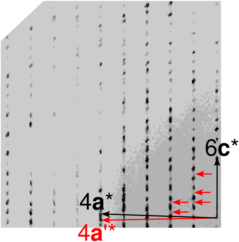
(h2l)* section of reciprocal space of the 1-nitronaphthalene twin under investigation. Multiples of reciprocal lattice basis vectors of the major domain are indicated in black, the 4a* vector of the minor domain in red.
4 Conclusion and outlook
The OD character of polytypes (all members of a family being locally equivalent) has often been used to rationalize the common occurrence of polytypism. Ordered domains of a polytypic compound are often of the MDO kind, because even though of similar energy, the fragment of one MDO polytype may be preferred during crystallization.
However, exceptions exist and in the case of the title compound both ‘rules of thumb’ are broken. We have shown that many of the core concepts of OD theory are just as useful in the context of non-OD polytypes and need only slight adjustments. We therefore suggest a generalized theory of polytypism, which can for example also describe ‘mixed’ polytypes where some layer contacts possess and others do not possess OD character.
The existence of non-MDO polytypes means that there is ‘communication’ of structural information beyond one MDO fragment during crystallization, for example by tilting of molecules or by propagation of ledge or screw dislocations.
A final question to answer is whether it is possible to grow the MDO polytypes or other non-MDO polytypes of the title compound.
Acknowledgments
TU Wien Bibliothek is acknowledged for financial support through its Open Access Funding Program.
-
Research ethics: Not applicable.
-
Author contributions: The authors have accepted responsibility for the entire content of this manuscript and approved its submission.
-
Competing interests: The authors state no conflict of interest.
-
Research funding: None declared.
-
Data availability: The raw data can be obtained on request from the corresponding author.
References
1. Groom, C. R.; Bruno, I. J.; Lightfoot, M. P.; Ward, S. C. Acta Crystallogr. 2016, B72, 171–179.10.1107/S2052520616003954Suche in Google Scholar PubMed PubMed Central
2. Dornberger-Schiff, K.; Grell-Niemann, H. Acta Crystallogr. 1961, 14, 167–177. https://doi.org/10.1107/s0365110x61000607.Suche in Google Scholar
3. STOE. X-Area 1.31.175.0, LANA 2.6.2.0. STOE & Cie GmbH: Darmstadt, Germany, 2021.Suche in Google Scholar
4. Sheldrick, G. M. Acta Crystallogr. 2015, A71, 3–8.10.1107/S2053273314026370Suche in Google Scholar PubMed PubMed Central
5. Sheldrick, G. M. Acta Crystallogr. 2015, C71, 3–8.Suche in Google Scholar
6. Hahn, T.; Aroyo, M. I. Space-Group Symmetry; International Tables For Crystallography, Vol. A; IUCr: Chester, 2016; Chapter 2.1.2; pp. 144–148.10.1107/97809553602060000114Suche in Google Scholar
7. Ferraris, G.; Makovicky, E.; Merlino, S. Crystallography of Modular Materials; IUCr Monographs on Crystallography, Vol. 15; Oxford University Press: Oxford, 2008.10.1093/acprof:oso/9780199545698.001.0001Suche in Google Scholar
8. Subperiodic Groups ; Kopsky, V.; Litvin, D. B.; Eds.; International Tables for Crystallography, Vol. E; IUCr: Chester, 2006.Suche in Google Scholar
9. Dornberger-Schiff, K. Krist. Tech. 1979, 14, 1027–1045. https://doi.org/10.1002/crat.19790140903.Suche in Google Scholar
10. Stöger, B.; Pokorny, B.; Lumpi, D.; Zobetz, E.; Fröhlich, J. Z. Kristallogr. 2013, 228, 106–112. https://doi.org/10.1524/zkri.2013.1592.Suche in Google Scholar
11. Spackman, M. A.; Jayatilaka, D. CrystEngComm 2009, 11, 19–32. https://doi.org/10.1039/b818330a.Suche in Google Scholar
12. Spackman, P. R.; Turner, M. J.; McKinnon, J. J.; Wolff, S. K.; Grimwood, D. J.; Jayatilaka, D.; Spackman, M. A. J. Appl. Crystallogr. 2021, 54, 1006–1011. https://doi.org/10.1107/s1600576721002910.Suche in Google Scholar PubMed PubMed Central
13. Ďurovič, S. EMU Notes Mineral. 1997, 1, 3–28.Suche in Google Scholar
14. Dornberger-Schiff, K. Acta Crystallogr. 1982, A38, 483–491.10.1107/S0567739482001041Suche in Google Scholar
15. Kader, T.; Kautny, P.; Stöger, B.; Fröhlich, J. Z. Kristallogr. 2017, 232, 375–384. https://doi.org/10.1515/zkri-2016-2040.Suche in Google Scholar
16. Ito, T.; Sadanaga, R. Proc. Jpn. Acad. 1976, 52, 119–121. https://doi.org/10.3792/pja/1195518372.Suche in Google Scholar
17. Nespolo, M.; Souvignier, B.; Stöger, B. Acta Crystallogr. 2020, A76, 334–344.10.1107/S2053273320000650Suche in Google Scholar PubMed PubMed Central
18. Nespolo, M.; Stöger, B. Cryst. Res. Technol. 2024, 59, 2300244. https://doi.org/10.1002/crat.202300244.Suche in Google Scholar
19. Fichtner, K. Beitr. Algebra Geom. 1977, 6, 71–99.Suche in Google Scholar
20. Ďurovič, S. Krist. Tech. 1979, 14, 1047–1053. https://doi.org/10.1002/crat.19790140904.Suche in Google Scholar
21. Grimmer, H.; Nespolo, M. Z. Kristallogr. 2006, 221, 28–50. https://doi.org/10.1524/zkri.2006.221.1.28.Suche in Google Scholar
Supplementary Material
This article contains supplementary material (https://doi.org/10.1515/zkri-2024-0089).
© 2024 the author(s), published by De Gruyter, Berlin/Boston
This work is licensed under the Creative Commons Attribution 4.0 International License.
Artikel in diesem Heft
- Frontmatter
- In this issue
- Inorganic Crystal Structures (Original Paper)
- Synthesis, characterization and structure-property relations in mullite-type Pb2(Pb1−xSn x )O4 solid solution
- Temperature-dependent diffraction studies on the stannides Sr3Rh4Sn4, Sr3Ir4Sn4 and Sr2.43Eu0.57Ir4Sn4
- Organic and Metalorganic Crystal Structures (Original Paper)
- The crystal and molecular structure of (R)-sirtinol – C26H22N2O2 – a chemo-sensitive enhancer and ligand in metal complexes with important bio-inorganic applications
- Synthesis and structural characterization of supramolecular cocrystals of [(4-cyano-1-methylpyridinium)2-(18-crown-6)] diiodide
- 1-Nitronaphthalene, a non-OD, non-MDO polytype
- Synthesis and crystal structure of a tripeptide comprising a centrally placed non-coded aromatic γ-amino acid