Comparison of the Vibration Response of a Rotary Dobby with Cam-Link and Cam-Slider Modulators
-
Hongbin Yu
 ,
Honghuan Yin
,
Honghuan Yin

Abstract
This article presents the kinematic modeling and analysis of cam profiles of two different types of modulator: a cam-link and a cam-slider modulators. Kinematic and dynamic models of the two different modulators were established based on the motion curves of the main shaft of the rotary dobby. Simulations were carried out in Simulink to analyze the vibration responses under different rotary speeds, and vibration responses of the two mechanisms were compared. The results show that the cam-link modulator vibrates smoothly at speeds of <700 rpm, and theoretically, the speed should not exceed 1,400 rpm. The cam-slider modulator vibrates smoothly at speeds of <500 rpm, and theoretically, the speed should not exceed 1,000 rpm. The cam-slider modulator is more suitable for use at low speeds, whereas the cam-link modulator is more appropriate for high speeds. When both the cam-slider and cam-link modulators operate at high speeds, vibration distortion occurs, leading to bifurcation and chaotic vibration. Further knowledge of the complex behaviors associated with detachment of the follower from the cam can support the design of more sophisticated controllers aimed at avoiding follower detachment.
1 Introduction
The rotary dobby is currently the most advanced high-speed opening device used in modern high-speed weaving machines. The dobby mechanism divides the warp yarn into two layers according to a certain rule, and a channel is formed, allowing the weft thread to pass through. This is achieved by converting the rotational motion of the main shaft of the weaving machine into the up-and-down motion of the frame. Nowadays, the rotary dobby is widely used in shuttleless looms, such as the rapier loom and air-jet loom, due to its compact structure, high motion accuracy, and the ability to achieve simple control and stable operation [1,2,3,4].
As one of the most important components, the rotary transmission mechanism is crucial to the performance of the rotary dobby. A modulator transforms uniform rotary motion of the weaving machine into non-uniform rotary motion to the dobby main shaft and determines the heald frame motion characteristics of the loom. The requirements of the loom can be met using conjugate cams and linkages or sliders with well-defined characteristics. However, further studies on the dynamic performance of various rotary transmission mechanisms are required [5, 6]. Cam-follower mechanisms are widely used in modern machinery due to several attractive features, such as a simple design, low-cost manufacturing, and versatility.
The cam follower represents, in essence, the core of the rotary transmission. In high-speed cam-driven mechanisms, the motion accuracy of the follower affects the overall performance of the machine. Several researchers have investigated the influence of cam profile accuracy and system flexibility on the output motion. Rothbart [7] proposed a method for predicting the follower response to irregularities on the cam surface. In another study, Koster [8] used a four degrees-of-freedom model to simulate the effects of backlash and camshaft deflection on the output of the mechanism. Kim and Newcombe [9] and Grewal and Newcombe [10] investigated the combined effects of geometric inaccuracies, kinematic errors, and dynamic errors. Norton [11,12,13] investigated the effects of manufacturing tolerances on the dynamic performance of eccentric and double dwell cams through experimental analyses. Besides, Wu and Chang [14] proposed an analytical method for analyzing the effects of mechanical errors in disc-cam mechanisms.
Complex behaviors in mechanical devices with impacts, as well as other types of piecewise-smooth dynamical systems, have become important topics of ongoing research [15,16,17,18]. At high rotary speeds, contact loss between the cam and the follower can reduce engine performance [19, 20], particularly in terms of efficiency, fuel consumption, and emissions [21]. Gianluca and Domenico [22] presented a preliminary study on the control of follower vibrations in cam-follower mechanisms when acting directly on the follower.
The research described earlier has laid a foundation for further analyses of the kinematic characteristics and dynamics of rotary transmission mechanisms of the rotary dobby. The speed of modern looms is continuously increasing, in pursuit of increased productivity, however, problems associated with higher operating speeds, such as machine vibrations and reduced stability, can shorten the lifespan of machines and must be solved. In-depth studies on the dynamic performance dobby rotary transmission mechanism, a key part of the opening mechanism, could help to solve these problems. However, the complex behaviors of transmission mechanisms have made it difficult to establish an accurate model of the rotary dobby. An accurate dynamics model of the dobby rotary transmission mechanism would provide the basis for studying and optimizing the dynamic performance of the mechanism and improve the efficiency of shuttleless weaving machines and product quality [23].
2 Physical models
2.1 Motion principle of modulators
Schematic drawings of the cam-link (CL) and cam-slider (CS) modulators are presented in Figure 1(a) and (b), respectively. The CL modulator, shown in Figure 1(a), consists of a gear, conjugate cam (including main cam and auxiliary cam (aux cam)), roller, swing arms, links, and main shaft. The swing arms are fixed to the gear. When the loom is running, the swing arms are hinged to the gear, and motion is transmitted to the cam rollers. The rotational speed of the gear is uniform. The conjugate cam is fixed to the dobby body, such that the four rollers move along the main and auxiliary cam contours of the conjugate cam. Clockwise rotation of the follower rollers causes the links to move, which drives the main shaft of the dobby.

Schematic illustration of the motion principles of the dobby modulator. (a) Cam-link modulator and (b) Cam-slider modulator.
Similarly, the CS modulator, shown in Figure 1(b), consists of a gear, conjugate cam (including main cam and auxiliary cam), rollers, swing arms, sliders, and the main shaft. The swing arms are fixed on the large gear. When the loom is running, the slider is embedded in the groove of the slide rack. As the gear continuously rotates, the slider rack and main shaft rotate synchronously. The groove direction ensures the swing arms always travel toward the center of the main shaft, and the groove direction can be altered by the conjugate cam. The swing arms are equipped with four rollers. The groove direction of the swing arms can be changed by rotating the gear according to certain rules, resulting in rotation of the dobby main shaft.
2.2 Acquiring the cam profile
The cam profile is an important aspect of cam-follower systems and is typically designed to move the follower in the desired manner [24,25,26]. Given the wide range of applications, there is a wide variety of possible cam geometries, ranging from cycloidal cams to cam motion designed using spline functions to accommodate discontinuities in the acceleration of the follower. In the present study, first we assume that the main shaft of the dobby will have the same kinematic curves for both modulators. Then, cam profiles of the CL and CS modulator can be obtained. Figure 2 illustrates the kinematic motion characteristics of the main shaft of the modulators.

Kinematic motion characteristics of modulators, which are the same for both the cam-link and cam-slider modulators. (a) Angular displacement and velocity and (b) angular acceleration.
2.2.1 The CL modulator
Figure 3 presents a schematic diagram of the CL modulator. The angle φ of link OB is a known parameter and φ is the main shaft angle of the modulator.

Sketch of the cam-link modulator.
In Figure 3, ω is the angular velocity of the gear. The starting position of the cam swing arm coincides with the hinge point C of the gear. The gear rotation angle θ in the Cartesian coordinate (X, Y) system can be expressed as θ = ωt.
From the geometric relationship:
where xB = lOB cos φ, yB = lOB sin φ, xc = lOC cos θ, and yC = lOC sin θ.
From Eq. (1), the point A (xA,yA) can be obtained.
The distance between the cam actual profile and the cam pitch curve is equal to the roller radius r. To obtain the coordinates of the corresponding point T (xT, yT) on the actual main cam profile, distance r is taken as the distance from the main cam profile along the direction normal to any point A.
The slope of the line n − n – normal to the main cam pitch curve A is
where γ is the angle between the normal line n – n and the x -axis; (xA, yA) are coordinates of any point A on the main cam pitch curve.
Eq. (2) can be rewritten as
According to Eq. (1)–(3), the coordinates of point T (xT, yT) of the actual main cam profile can be determined as follows:
Then, the analytical solution of the cam profile equation can be determined using Eq. (1)–(4).
To obtain the coordinates of the corresponding point M (xM, yM) on the actual auxiliary cam profile, the auxiliary cam profile along the direction normal to any point D is taken as distance r.
Based on the law of cosines:
Using Eq. (5), point D (xD, yD) can be obtained.
From the geometric relationship:
The coordinates of point M (xM, yM) of the actual auxiliary cam profile can be determined, as follows:
2.2.2 The CS modulator
Figure 4 presents the structure of the CS modulator. The radius of the roller is r1; point C1 on the gear is centered at point O1; and the theoretical cam profile is the trajectory formed by point A1.

Sketch of cam-slider modulator.
Point A1 (xA1, yA1) satisfies
Point C1 (xC1, yC1) satisfies
According to the law of cosines:
The geometric relationship is
where angle β, lA1 C1, lO1C1, and angle φ are known parameters.
From Eq. (8)–(13), the point A1 (xA1, yA1) can be obtained.
Similar to the principle of the CL modulator mechanism:
The coordinates of point T1 (xT1, yT1) of the actual main cam profile can be determined as
From the geometric relationship:
From Eq. (16), point D1 (xD1, yD1) can be obtained.
The coordinates of point M1 (xM1, yM1) of the actual auxiliary cam profile can be determined as
where
2.2.2 Geometric parameters
The conjugate cam profiles were obtained using geometrical methods and theoretical calculations. Parameter values of the CL and CS modulators are presented in Table 1. Eq. (1)–(18) were used to ascertain the conjugate cam profiles of the CL and CS modulators. All calculations were performed using a computer program written and compiled in Microsoft Visual Studio 2012 on a personal computer.
Geometric parameters of CL and CS modulators
| CL modulator | Value | Unit | CS modulator | Value | Unit |
|---|---|---|---|---|---|
| lAB | 47 | mm | lA1 C1 | 47 | mm |
| lAC | 81 | mm | lO1 C1 | 81 | mm |
| lOB | 60 | mm | – | – | – |
| lOC | 56 | mm | – | – | – |
| r | 31 | mm | r1 | 31 | mm |
| α | 120 | deg | β1 | 56 | deg |
CL, cam-link, CS, cam-slider.
3 Dynamic model of modulator
3.1 Dynamic model
The dobby modulator was modeled as two masses, three springs, and three dampers. Figure 1(a) and (b) shows models of the CL and CS modulators, respectively. When the gear rotates at low speeds, the cam surface and the contact points of rollers 1 and 2 never separate. Roller 1 meets the desired displacement characteristic s1 (θ) and roller 2 meets characteristic s2 (θ). Assuming no assembly errors, when the two rollers are in close contact with the conjugate cam profile, then s2 (θ) = s1 (θ). Figure 5(a) shows the dynamic models of the CL and CS modulators. In the CL modulator dynamic model, m1 (follower 1-CL) is the concentrated mass of cam roller 1, swing arm 1, and half of the link. In the ideal case, displacement y1 is the expected displacement and m2 (follower 2-CL) is the conc entrated mass of cam roller 2, swing arm 2, and half of swing arm 3.

Schematic representations and dynamic models of cam-link (CL) and cam-slider (CS) modulators. (a) Dynamic models, (b) equivalent dynamics model, and (c) force analysis.
Moreover, in the CS modulator dynamic model, m1 (follower 1-CS) is the concentrated mass of cam roller 1, swing arm 1, link 1, and half of the main shaft link; m2 (follower 2-CS) is the concentrated mass of cam roller 2 and swing arm 2. During high-speed motion, the intermediate link may experience irregular vibrations, which cause noise and friction, abrasion of moving parts, and reduce the service life of the system. Therefore, displacement y2 of the follower 2-CS should also be taken seriously (y1 and y2 are absolute displacements).
The additional spring and damping elements are simplified as spring coefficients k1, k2, and k3 and viscous damping coefficients b1, b2, and b3 connecting masses m1 and m2 with the contact points, as shown in Figure 5(b).
The detached bodies of follower 1-CL and follower 2-CL are considered for force analysis. In the vertical direction, follower 1-CL and follower 2-CL are subjected to an elastic restoring force and a damping force. The force analysis is presented in Figure 5(c). The CL and CS modulators have the same dynamic model.
The dynamic equations can be written as [27]
Eq. (19) can then be reorganized as
3.2 Dynamic model response
The nonlinear system of equations, presented in Eq. (20), was implemented in Simulink using the parameters listed in Table 2. The Runge-Kutta method was used to calculate y1 and y2 of the two mechanisms. Then, the dynamics of the cam-follower system were investigated, paying particular attention to the impact behavior following the detachment of the follower from the cam.
Dynamic parameters of CL and CS modulators
| Parameter | CS modulator | CL modulator | Unit |
|---|---|---|---|
| m1 | 4.5 | 6.0 | kg |
| m2 | 4.5 | 2.5 | kg |
| k1 | 8.0 × 10⁸ | 8.0 × 10⁸ | N/m |
| k2 | 5.0 × 10¹⁰ | 5.0 × 10¹⁰ | N/m |
| k3 | 8.0 × 10⁸ | 8.0 × 10⁸ | N/m |
| b1 | 2.0 | 2.0 | Ns/m |
| b2 | 3.0 | 3.0 | Ns/m |
| b3 | 2.0 | 2.0 | Ns/m |
CL, cam-link, CS, cam-slider.
Figure 6 shows the value of s1 (θ) for the two types of modulators when the rotational speed of the gear is very low. Owing to the different mechanical structures of the two modulators, the cam contours must also differ to achieve the same motion characteristics of the spindle output. Therefore, the s1 (θ) curves produced by each modulator are different.

Comparison of s1 (θ) curves of cam-link and cam-slider modulators.
4 Results and discussion
Cam-follower systems are particularly sensitive to variations in gear rotational speed ω. Here, we sought to uncover the complex dynamics observed under various rotational velocities ω due to collisions between the cam and the follower.
4.1 Vibration response of CL modulator
To understand the vibration response of follower 1-CL, a bifurcation diagram was derived for different values of ω, as shown in Figure 7. The evolution of gear angle θ with rotational speed is presented in Figure 8(a)–(d).
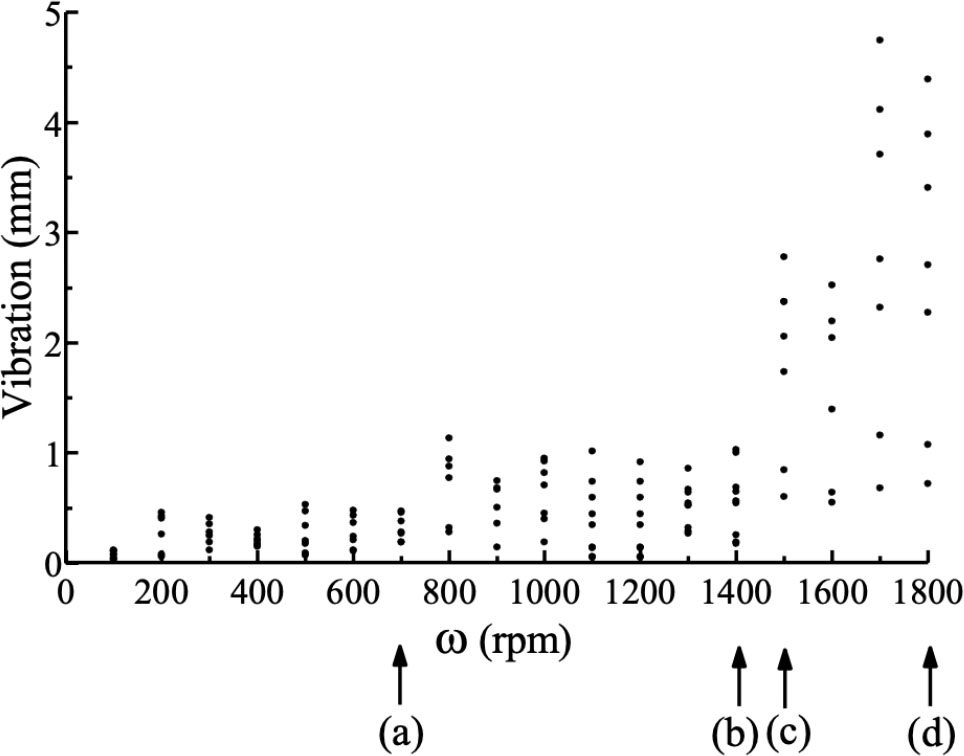
Bifurcation diagram of follower 1-CL system with changes in gear rotational speed ω.
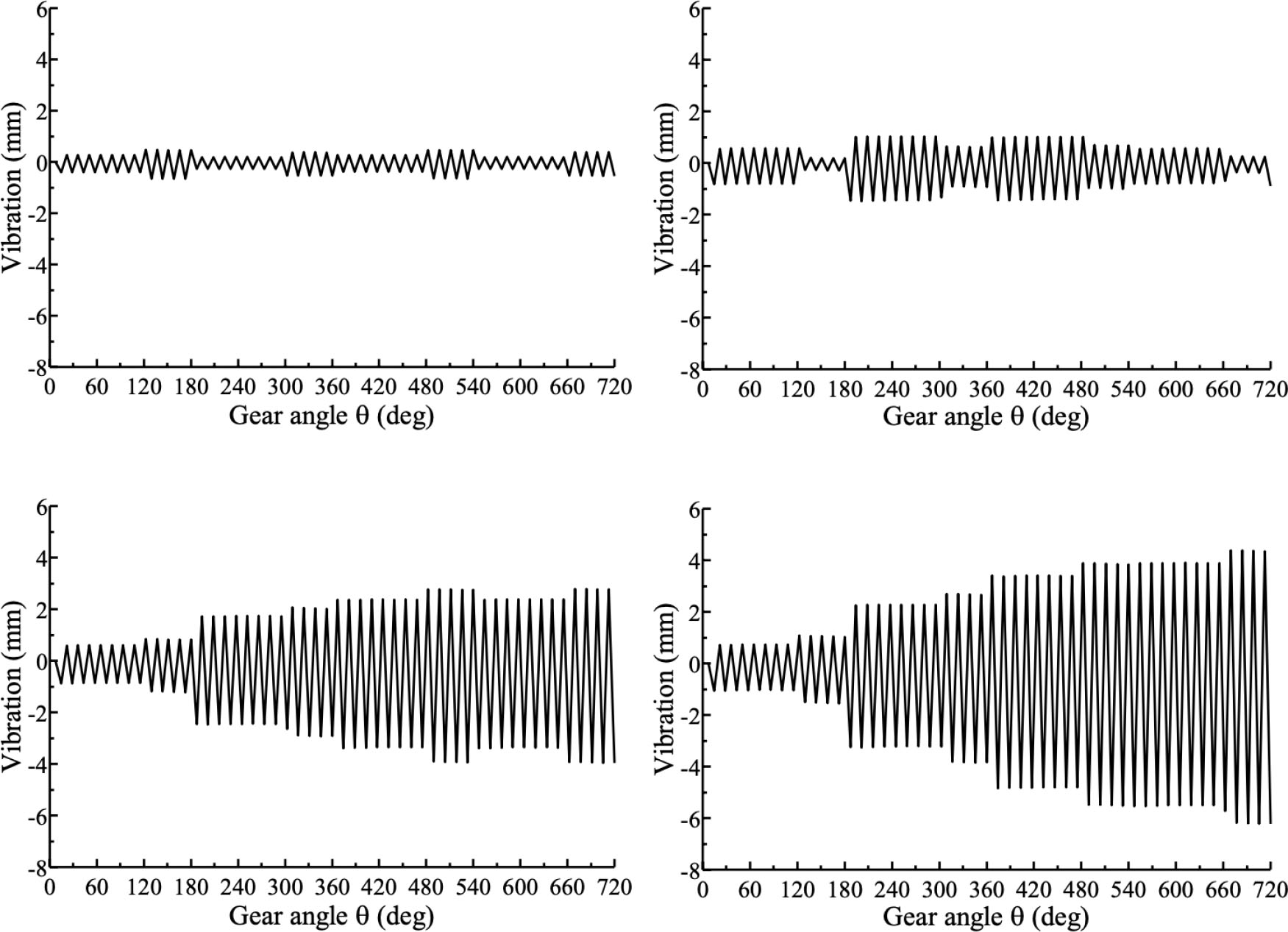
Gear angle θ. Evolution of the system response for different values of ω. (a) ω = 700 rpm, (b) ω = 1,400 rpm, (c) ω = 1,500 rpm, and (d) ω = 1,800 rpm.
Figure 7 shows the vibration response of the follower 1-CL at about 700 rpm, and the corresponding vibration response to the gear angle θ is shown in Figure 8(a). For a large range of ω ∈ [0, 700], the vibration of the system is relatively stable. Severe vibration suddenly occurs at about 1,500 rpm, which rapidly evolves into a chaotic attractor, as illustrated in Figure 8(c) and (d).
In addition, the vibration responses of follower 2-CL at different values of ω were analyzed. Trends were similar for follower 2-CL and follower 1-CL. Taking ω = 1,000 rpm as an example, the vibration response of follower 1-CL and follower 2-CL are compared in Figure 9.

Comparison of follower-CL displacements when ω = 1,000 rpm.
According to the above analysis, the maximum value of ω cannot theoretically exceed 1,400 rpm in the CL modulator system and should ideally operate under 700 rpm.
4.2 Vibration of CS modulator
The bifurcation diagram of follower 1-CS position of CS modulator is presented in Figure 10. As an example, trajectories at different instances in time are shown in Figure 11 for two gear cycles only.

Experimental bifurcation diagram of follower 1-CS position of CS modulator versus gear rotational speed ω.

Evolution of gear angle θ of the system for different values of ω. (a) ω = 500 rpm, (b) ω = 1,000 rpm, (c) ω = 1,100 rpm, and (d) ω = 1,800 rpm.
Figure 10 shows the vibration response of follower 1-CS at about 500 rpm, and the corresponding vibration response to the gear angle θ is shown in Figure 11(a). For large ω ∈ [0, 500], the vibration response of the CS modulator system is stable. However, severe vibration suddenly occurs at about 1,100 rpm. The behavior is similar to that of the CL modulator, and again, quickly evolves into a chaotic attractor, as shown in Figure 11(c)–(d).
Similar to the analysis of follower 2-CL, vibration characteristics were also calculated for follower 2-CS at different values of ω. It can be concluded that the vibration conditions of follower 1-CS and follower 2-CS are approximately the same. Figure 12 shows a comparison of the follower-CS displacements when ω = 1,000 rpm.

Comparison of follower-CS displacements when ω = 1,000 rpm.
Theoretically, the maximum value of ω should not exceed 1,000 rpm, and ideally, the CS modulator system should operate under 500 rpm.
4.3 Comparison of vibration results
Bifurcation diagrams of the vibration/displacement of follower 1-CL and follower 1-CS are presented in Figure 13. In Figure 13(a), the vibration/displacement is equal to the vibration of follower 1-CL/Sl (θ) of the CL modulator. In Figure 13(b), the vibration/displacement is equal to the vibration of follower 1-CS/S1(θ) of the CS modulator.

Vibration/displacement of follower 1-CL and follower 1-CS. (a) Vibration/displacement of follower 1-CL and (b) vibration/displacement of follower 1-CS.
From Figure 13, it can be observed that, overall, the vibration/displacement of follower 1-CS is smaller than that of follower 1-CL. The ideal speed of the CL modulator is under 700 rpm, however, theoretically, the modulator can be used at speed of up to 1,400 rpm. On the other hand, the ideal speed of the CS modulator is under 500 rpm, and theoretically, the modulator can be used at speed of up to 1,000 rpm. Based on the analysis of vibration/displacement, it can be concluded that the CS modulator is suitable for gear speeds ω under 500 rpm, and the CL modulator is suitable for high speeds.
5 Conclusions
Based on the kinematic characteristics of the main shaft, this article modeled and analyzed the cam profiles of the CL and CS modulators, which were used to establish physical models of the modulators. The main features of the two proposed modulators were described and the dynamics of each cam-follower system were investigated. As the gear speed ω changes, the modulator systems exhibit complex vibration behaviors. Periodic impact behavior emerged, characterized by several impacts and chattering. The preliminary results suggest the presence of bifurcations and chaotic vibrations in the system.
Dynamic models of the two mechanisms were established, and simulations were performed in Simulink to analyze and compare vibration responses at different speeds. The results show that the CL modulator vibrates smoothly when ω is <700 rpm, and theoretically, the speed cannot exceed 1,400 rpm; the CS modulator vibrates smoothly when ω is <500 rpm, and theoretically, the speed cannot exceed 1,000 rpm. Thus, the CS modulator is more suitable to use at low speeds, whereas the CL modulator is more suitable to use at high speeds. When the speed is high, vibration distortion will occur in the vibration response of both mechanisms, leading to the bifurcation.
We wish to emphasize that the results reported in this paper can be used to (1) establish an inverse model of the cam profile and solve the conjugate cam profiles and (2) determine the vibration characteristics of the CL and CS modulators. A comparative analysis was performed to determine the range of speeds for which complex behaviors, such as vibration stability, sudden vibration changes, and bifurcations, will occur in these systems against the gear rotational speed ω. The analysis presents the theoretical results of the shock system vibration and guides future practical work. In addition, we have provided a more in-depth understanding of the complex behaviors associated with detachment of the follower from the cam to support the design of more sophisticated controllers aimed at avoiding follower detachment.
Acknowledgments
The authors disclosed receipt of the following financial support for the research, authorship, and/or publication of this article: This research was supported by the National Key R&D Program of China (2017YFB1104202).
References
[1] Jin, G. G., Wei, X. Y., Wei, Z., Chang, B. Y., Zhang, X. Y. (2018). Dynamic analysis and optimization of rotary dobby lifting comprehensive mechanism. Journal of Textile Research, 39(9), 160–168.Search in Google Scholar
[2] Yuan, R. W., Zhu, L. L., Lv, X. K., Yang, J. M. (2019). Modeling of rotary shifting motion characteristics of electronic dobby and influence thereof on shedding mechanisms driving. Journal of Textile Research, 40(12), 127–133.Search in Google Scholar
[3] Eren, R., Özkan, G., Karahan, M. (2005). Comparison of heald frame motion generated by rotary dobby and crank & cam shedding motions. Fibres & Textiles in Eastern Europe, 13(4), 78–83.Search in Google Scholar
[4] Abdulla, G., Can, O. (2018). Design of a new rotary dobby mechanism. Industria Textile, 69(6), 429–433.10.35530/IT.069.06.1484Search in Google Scholar
[5] Bílek, M., Mrazek, J. (1998). Dynamic stress of heald shaft of weaving looms. Fibres and Textiles, 3, 131–134.Search in Google Scholar
[6] Bílek, M., Skřivánek, J. (2013). Mathematical modeling of the system shedding motion - heald - warp. AUTEX Research Journal, 13(2), 42–46.10.2478/v10304-012-0022-8Search in Google Scholar
[7] Rothbart, H. A. (1956). Cams: Design, dynamics, and accuracy. John Wiley and Sons Ltd (New York), 150–200.Search in Google Scholar
[8] Koster, M. P. (1974). Vibrations of cam mechanism. Palgrave (London), 120–150.10.1007/978-1-349-02455-1_7Search in Google Scholar
[9] Kim, H. R., Newcombe, W. R. (1982). The effect of cam profile errors and system flexibility on cam mechanism output. Mechanism and Machine Theory, 17, 57–72.10.1016/0094-114X(82)90024-6Search in Google Scholar
[10] Grewal, P. S., Newcombe, W. R. (1988). Dynamic performance of high-speed semi-rigid follower cam systems - Effects of cam profile errors. Mechanism and Machine Theory, 23, 121–133.10.1016/0094-114X(88)90089-4Search in Google Scholar
[11] Norton, R. L. (1988). Effect of manufacturing method on dynamic performance of cams - an experimental study. Part I - Eccentric cams. Mechanism and Machine Theory, 3, 191–199.10.1016/0094-114X(88)90104-8Search in Google Scholar
[12] Norton, R. L. (1988). Effect of manufacturing method on dynamic performance of cams - An experimental study. Part II - Double dwell cams. Mechanism and Machine Theory, 23, 201–208.10.1016/0094-114X(88)90105-XSearch in Google Scholar
[13] Norton, R. L. (2002). Cam design and manufacturing handbook. Industrial Press (New York), 580–590.Search in Google Scholar
[14] Wu, L. I., Chang, W. T. (2005). Analysis of mechanical errors in disc cam mechanisms. Proceedings of the Institution of Mechanical Engineers-Part C: Journal of Mechanical Engineering Science, 219(2), 209–224.10.1243/095440605X8405Search in Google Scholar
[15] Brogliato, B. (1999). Nonsmooth mechanics, dynamics and control. (2nd ed.) Springer Verlag (London), 448–475.10.1007/978-1-4471-0557-2Search in Google Scholar
[16] di Bernardo, M., Budd, C., Champneys, A. R., Kowalczyk, P., Nordmark, A. B., et al. (2008). Bifurcations in nonsmooth dynamical systems. Society for Industrial and Applied Mathematics, 50(4), 629–701.10.1137/050625060Search in Google Scholar
[17] Zhusubalyev, Z. T., Mosekilde, E. (2003). Bifurcations and Chaos in Piecewise - Smooth dynamical systems. World Scientific (Singapore), 230–285.10.1142/5313Search in Google Scholar
[18] Norton, R. L., Eovaldi, D., Westbrook, J., Stene, R. L. (1999). Effect of the valve-cam ramps on valve train dynamics. SAE International (USA).10.4271/1999-01-0801Search in Google Scholar
[19] Teodorescu, M., Votsios, V., Rahnejat, H., Taraza, D. (2006). Jounce and impact in cam-tappet conjunction induced by the elastodynamics of valve train system. Meccanica, 41(2), 157–171.10.1007/s11012-005-1609-0Search in Google Scholar
[20] Kushwaha, M., Rahnejat, H., Jin, Z. M. (2001). Valve-train dynamics: A simplified tribo-elasto-multi-body analysis. Proceedings of the Institution of Mechanical Engineers -Part K: Journal of Multi-body Dynamics, 214, 1464–4193.10.1243/1464419001544269Search in Google Scholar
[21] Choi, T. D., Eslinger, O. J., Kelley, C. T., David, J. W., Etheridge, M. (2000). Optimization of automotive valve train components with implicit filtering. Optimization and Engineering, 1(1), 9–27.10.1023/A:1010071821464Search in Google Scholar
[22] Gianluca, G., Domenico, M. (2010). On the direct control of follower vibrations in cam-follower mechanisms. Mechanism and Machine Theory, 45(1), 23–35.10.1016/j.mechmachtheory.2009.07.010Search in Google Scholar
[23] Zhang, C. (2008). Machinery dynamics. (2nd ed.) Higher Education Press (Beijing), 230–300.Search in Google Scholar
[24] Qiu, H., Lin, C. J., Li, Z. Y., Ozaki, H. (2005). A universal optimal approach to cam curve design and its applications. Mechanism and Machine Theory, 40(6), 669–692.10.1016/j.mechmachtheory.2004.12.005Search in Google Scholar
[25] Mosier, R. G. (2000). Modern cam design. International Journal of Vehicle Design, 23(1/2), 38–55.10.1504/IJVD.2000.001881Search in Google Scholar
[26] Flocker, F. W. (2012). A versatile cam profile for controlling interface force in multiple-dwell cam-follower systems. Journal of Mechanical Design, 134(9), 094501-1-6.10.1115/1.4007146Search in Google Scholar
[27] Chen, F. Y., Polvanich, N. (1975). Dynamics of high-speed cam-driven mechanisns - Part 1: Linear system models. Journal of Engineering for Industry, 97(3), 769–775.10.1115/1.3438671Search in Google Scholar
© 2021 Hongbin Yu et al., published by Sciendo
This work is licensed under the Creative Commons Attribution 4.0 International License.
Articles in the same Issue
- AUTEX 2022 – 21st World Textile Conference Announcement
- Design and Development of a Novel Mechanism for the Removal of False Selvedge and Minimization of its Associated Yarn Wastage in Shuttleless Looms
- Empirical Analysis of the Impact Strength of Textile Knitted Barrier Meshes
- Characteristics of Laminates for Car Seats
- Methodology of Optimum Selection of Material and Semi-Folded Products for Rotors of Open-End Spinning Machine
- Fabrication of Multifunctional Nano Gelatin/Zinc Oxide Composite Fibers
- 3D Design of Clothing in Medical Applications
- Development of Subcontractor Selection Models Using Fuzzy and AHP Methods in the Apparel Industry Supply Chain
- Evaluation of Thermal Properties of Certain Flame-Retardant Fabrics Modified with a Magnetron Sputtering Method
- Comparative Study of Long- and Short-Stretch Woven Compression Bandages
- Natural Polymers on the Global and European Market - Presentation of Research Results in the Łukasiewicz Research Network – Institute of Biopolymers and Chemical Fibers-Case Studies on the Cellulose and Chitosan Fibers
- The Fabrication of Cassava Silk Fibroin-Based Composite Film with Graphene Oxide and Chitosan Quaternary Ammonium Salt as a Biodegradable Membrane Material
- Eco-Fashion Designing to Ensure Corporate Social Responsibility within the Supply Chain in Fashion Industry
- Phototherapy in the Treatment of Diabetic Foot — A Preliminary Study
- Comparison of the Vibration Response of a Rotary Dobby with Cam-Link and Cam-Slider Modulators
- Numerical Simulation of Solar Radiation and Conjugate Heat Transfer through Cabin Seat Textile