Compressive Property of an Auxetic-Knitted Composite Tube Under Quasi-Static Loading
-
Andrews Boakye


Abstract
This research investigates the compressive property of a novel composite based on a weft-knitted auxetic tube subjected to a quasi-static compression test. In order to maximize the influence of the fiber content on the compression test, a Kevlar yarn was used in knitting the tubular samples using three different auxetic arrow-head structures (i.e. 4 × 4, 6 × 6 and 8 × 8 structure). A quasi-static compression test was conducted under two different impact loading speeds (i.e. 5 mm/min and 15 mm/min loading speed). The results indicate that the energy absorption (EA) property of the auxetic composite is highly influenced by the auxeticity of the knitted tubular fabric.
1 Introduction
Generally, materials that exhibit expansion transverse to the direction of applied force are considered as auxetic materials [1,2,3,4,5,6]. These materials possess enhanced properties that include robust indentation resistance and energy absorbance, rugged fracture toughness, improved crack growth resistance and many more. Auxetic materials that are used in composites have been noted to deliver better performance when compared to conventional composite materials. Compared with conventional composites, the auxetic composites have higher shear modulus, enhanced indentation resistance, synclastic curvature, better crack resistance and higher damping resistance [7].
Auxetic composite materials have recently been extensively applied in several fields due to their advantages of high performance to relatively low cost and weight. They are unique composite materials whose special properties such as superior energy absorption (EA), improved fracture toughness, indentation resistance, enhanced strength, better acoustic behavior, etc. [8] have given them a wider recognition in recent times. Due to their exhibition of the aforementioned properties, auxetic composite materials have found application in aerospace engineering, automotive industries, defense and protective material industries [9], smart sensors, filter cleaning and biomechanics [10] and various engineering fields. In aerospace engineering for instance, they are employed for reducing the noise in the aircraft fuselage, and their better formability property makes it easier to turn them into complex shapes and curved panels [11]. When fabricated with knitting technology, these composite materials further gain some excellent mechanical properties such as shear resistance, ability to fit to surfaces, breaking tenacity and so on.
Many composite materials made of metals, polymers and composite materials are designed to absorb impact energy under axial crushing, bending and/or combined loading [12]. An essential prerequisite is that the inherent morphology of these composite materials or structures must be able to dissipate large amounts of energy by controlled collapse in the event of a collision [13].
A couple of research reports cited in the literature confirm the superiority of auxetic materials and/or structures relative to their non-auxetic counterparts. In their report, Mohsenizadeh et al investigated the crash response and EA performance of three structures as follows: empty, conventional and auxetic foam-filled square tubes under quasi-static axial loading. Results after the test indicate that the auxetic foam-filled tube was superior to both empty and conventional foam-filled square tubes in all the studied crashworthiness indicators [14].
A proposed auxetic composite was fabricated by Jiang et al via an injecting and foaming process by using multilayer orthogonal auxetic structure as reinforcement and polyurethane foam as matrix. The negative Poisson’s ratio (NPR) effect and mechanical behavior of the composite under a quasi-static compression were investigated and compared with those of the pure polyurethane foam and non-auxetic composite. The results obtained after the study show that the auxetic composite fabricated has an obvious NPR effect and behave more like a damping material with a large range of deformation strains [15].
Even though studies on auxetic composites exist in the literature, there is no record of a tubular formed auxetic composite material. This study thus presents the EA property of novel weft-knitted auxetic composite tubes with three different Poisson’s ratios tested under quasi-static compression. The damage observations and the deformation of the structure were used in evaluating the behavior and nature of the knitted composite tube under the quasi-static compression test.
This research work aims at developing an auxetic composite tube with high EA characteristics that will find application in aerospace and automobile engineering.
2 Materials and methods
This section of the paper provides information about the experiment’s raw materials, sample design and fabrication methods, instruments and the testing methods.
2.1 Materials
Kevlar yarn was used in knitting the samples since it is noted for its high strength to weight ratio. The tensile property of the yarn was tested using Shanghai New Fiber Instrument Co. Ltd.’s universal material tensile testing machine YF-900 (China). The composite materials were fabricated using weft-knitted tubular fabrics knitted on a double bed flat knitting machine (Stoll CMS 530; H. Stoll AG & Co. KG, Germany). A JH-5539 epoxy used in reinforcing the knitted tube was procured from Hangzhou Wuhuigang Adhesives Co. Ltd (China). A customized resin application setup based on the Vacuum-Assisted Resin Transfer Molding (VARTM) process constructed at Jiangnan University Knitting Technology Center (KTC) lab was used. Quasi-static loading test was undertaken using a universal material tensile testing machine YF-900 by Yangzhou Daochun Test Machinery Company (China).
2.2 Methods
2.2.1 Characterization of yarn used
To analyze the physical properties of the Kevlar yarn used, a yarn tensile test was conducted. The gauge length of the specimen was 500 mm with a 300 mm/s velocity and a strain rate of 0.6. The test was run five times, and Table 1 shows the characteristics and detail results obtained from the tensile test.
Specifications of the Kevlar Yarn
| Linear density | Young’s modulus | Breaking strength | Elongation at break | Density |
|---|---|---|---|---|
| 0.22 tex | 8024.69 ksi | 840.0±14.0 cn/tex | 89.11±4.2% | 18.2±2.3g/cm3 |
2.2.2 Tubular fabric fabrication
Three different weft-knitted auxetic structures (i.e. 4 × 4, 6 × 6 and 8 × 8) were used in fabricating the tubular material. The structures were designed using Stoll M1 plus software. The movement of the needles during the fabrication of the auxetic tubular fabrics is shown in Figure 1. It is assumed that the initial position of the carriage is on the left hand side. In the course of the first movement of the carriage to the right hand side, four front loops are formed on each and every other active needle and then rack over the next needle and form four reverse loops also on each and every other active needle on the back needle bed.
![Figure 1 Sequential needle movement for the tubular fabric [2]](/document/doi/10.2478/aut-2019-0020/asset/graphic/j_aut-2019-0020_fig_001.jpg)
Sequential needle movement for the tubular fabric [2]
The same action had to be repeated on the rear needle bed but before that happens, the four reversed stiches that were formed on the rear needle bed have to be transferred back onto the front bed, and again upon repeating the same action on the rear needle bed, the face stiches that are formed on the front needle bed are transferred to the rear needle bed. The carriage then moves from the right hand side after the transfer back to the left to complete the first course.
The second course of knitting starts with a reverse loop on the left, racks over a needle to form four face loops to the right side and then again racks over another needle to form three reverse loops on the front needled bed. As usual, the needles that formed the face loops on the back needle bed have to be transferred back, as well as active needles from the back needle bed to form the reverse loops for the second course. The same knitting action is repeated on the back needle bed [2].
Figure 2 shows the computer simulation of structures to be knitted and their corresponding knitted samples for the 4 × 4, 6 × 6 and 8 × 8 structural patterns.
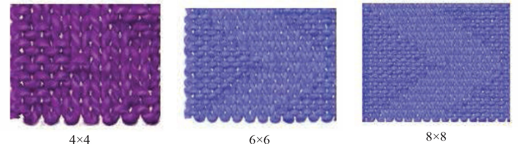
Simulated images of the three knitted structures
2.3 Poisson’s ratio of tubular fabric samples
Poisson’s ratios of the three tubular knitted fabrics were calculated using the relation stated below before making them into composite materials.
where ɛlat and ɛlong are the transverse and the longitudinal strains, respectively. Using the abovementioned formula, the Poisson’s ratio of 4 × 4 samples is −0.09, that of 6 × 6 is −0.02 and −0.14 for 8 × 8 sample, respectively.
2.4 Fabrication of the composite material
The resultant tubular weft-knitted fabric was used as the reinforcement material, a JH-5539 epoxy resin as the matrix and a VARTM process [16] was employed. The process is such that the composite is molded using a rigid mold that provides shaping and a thin flexible membrane over the reinforcement material, with outer atmospheric pressure compressing the material tight against the rigid mold surface. Vacuum is applied to assist the continuous flow of low-pressure infused resin from one side of the mold to the other. Vacuum eliminates air from the preform and helps the VARTM machine’s on-ratio measured and mixed flow of degassed air-free resin through the compressed composite fiber preforms below the vacuum bag. A single layer of the reinforcement material was used in the fabrication against a 2:1 resin ratio.
Unlike other flat composite materials whose fabrication through the VARTM process is quite simple, the same cannot be said of tubular composite materials. An undesirable effect was achieved after the researcher tried using the VARTM method for flat composites. The resulting tubular composite material had the side lying flat on the support being inundated with resin residue which hardened up and remained at the edges.
For easy understanding on how the resulting composite material had an undesired effect, an illustration on how the composite was made is presented in Figure 3a.
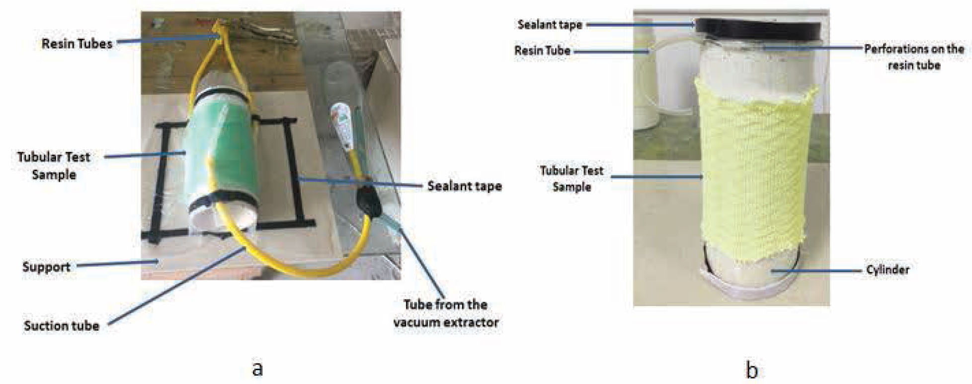
(a and b) Schematic representation of composite fabrication
In order to produce a quality and a more desired composite material, the researcher designed a new method for making a tubular composite material inspired by the VARTM process. The cylinder that holds the knitted tubular fabric was made to stand vertically instead of lying flat on a support. Again two flexible tubes were perforated and coiled around the cylinder, one on top to serve as the resin tube and the other at the bottom to serve as the vacuum extraction tube. It was then covered with a plastic bag. This technique ensured that the resultant composite material was farmed without any excess resin forming at the side of the cylinder. An illustration is presented in Figure 3b to show the designed method.
Figure 4 shows the composite material obtained after using the new method developed by the researcher. The sample has the dimension of 50 mm as height, 110 mm as internal diameter and 2 mm as thickness.
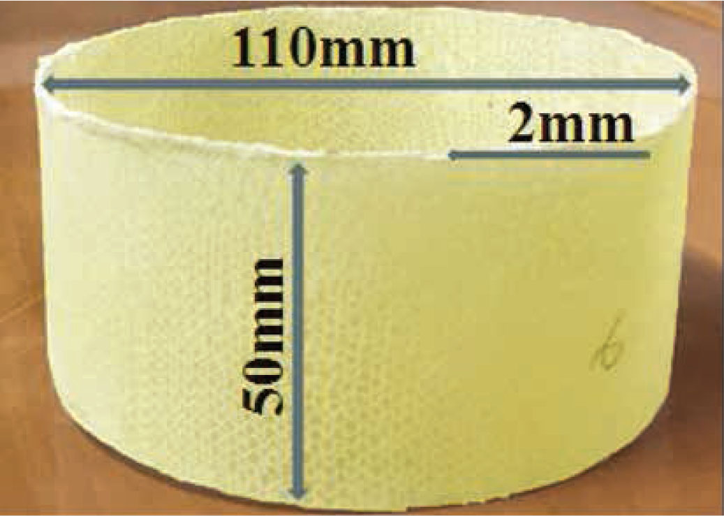
Tubular composite cut into the desirable sample size
2.4.1 Composite void ratio relation
The non-uniformity of a composite material as a result of some pore that remained unoccupied during the fabrication of the composite is referred to as void. These imperfections can alter the mechanical properties of the resultant composite materials and even minimize the performance as well as the lifespan of the material [17]. In view of this, the content of void should be checked after fabricating a composite material to ascertain its quality level.
Prior to checking the quality of the composite, the densities of the reinforcement, resin and composite material were separately measured. The weight of the resin content was measured and the theoretical density calculated. After the aforementioned quantities had been obtained, the void content/porosity was then calculated by the following equation:
where Vn is the void content, ρsample is the density of the composite which is measured in kg/m3. fm matrix and fm fiber are the mass fraction of the matrix and the fiber used in the work, respectively, and ρmatrix and ρfiber are the density of the matrix and the fiber, respectively.
The percentage value obtained after the calculation was 2.4%, indicating that the resultant composite was a desirable one as suggested in the literature [18, 19].
2.5 Quasi-static compression tests
Even though most studies that examined the energy absorbing capabilities of thin-walled composite materials have been based on axial crush analysis, this study opted for quasi-static compression due to the nature and small size of the samples under study. This test affords eliciting of strength characteristics of the samples in a more controlled and comprehensive manner. Quasi-static compression describes a compression mode where the volume of a system changes at a slow rate enough to allow the pressure to remain uniform and constant throughout the system [20]. Quasi-static compression tests were conducted by using a universal material tensile testing machine YF-900 with two circular compression plates and a 10 kN load cell. The samples were subjected to a quasi-static axial compression to failure with two different loading speed rates set at 5 mm/min and 15 mm/min. Also, the sample used as stated earlier had a height of 50 mm, a thickness of 2 mm and a diameter of 110 mm (Note: all samples had the same parameters). Testing was conducted on three different knitting structures (i.e. 4 × 4, 6 × 6 and 8 × 8) as stated earlier and as shown in Figure 5.
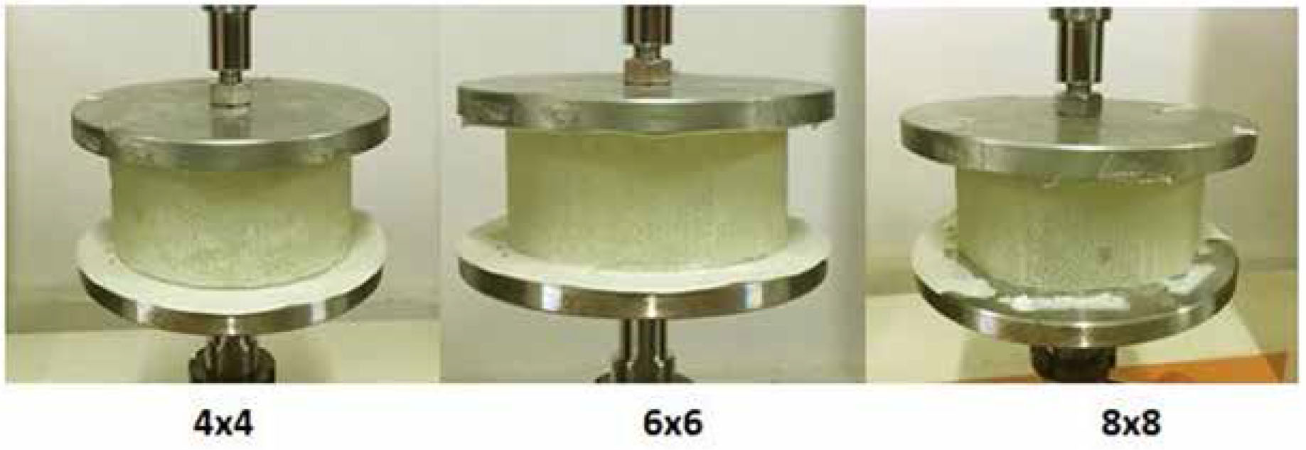
Samples for the three different knitting structures
Each knitted structure had six samples to which three of them were tested under 5 mm/min speed rate and the other three under 15 mm/min speed rate.
3 Results and discussion
To efficiently evaluate the absorbed energy of the tubular composite material, the following indicators were considered including EA, specific energy absorption (SEA) and peak crushing force Pmax. EA identifies a structure’s stable limit during axial crushing and can be mathematically calculated by the following equation:
where F denotes the crushing force, d and δ, respectively, denotes crushing distance and displacement.
Consequently, the SEA refers to the absorbed energy per unit mass of the structure, and it is mathematically calculated by the following formula:
where
Crushing force efficiency (CFE) refers to the uniformity of load–displacement curves of the crushing process. It can be mathematically calculated by:
where Pm denotes the capacity of energy absorbed by the structure.
3.1 Compression test and displacement curve analysis
Three structures were subjected to compression test at different loading speeds (5 mm/min and 15 mm/min) with each structure having six samples. Three of the samples were tested under 5 mm/min loading speed and the remaining three under 15 mm/min loading speed for each structure.
It is clearly seen in Figure 6a and b that impact resistance for all the samples under the two loading speeds recorded an initial impact that accelerated gradually. The responses are indicated in the slope of their curves.
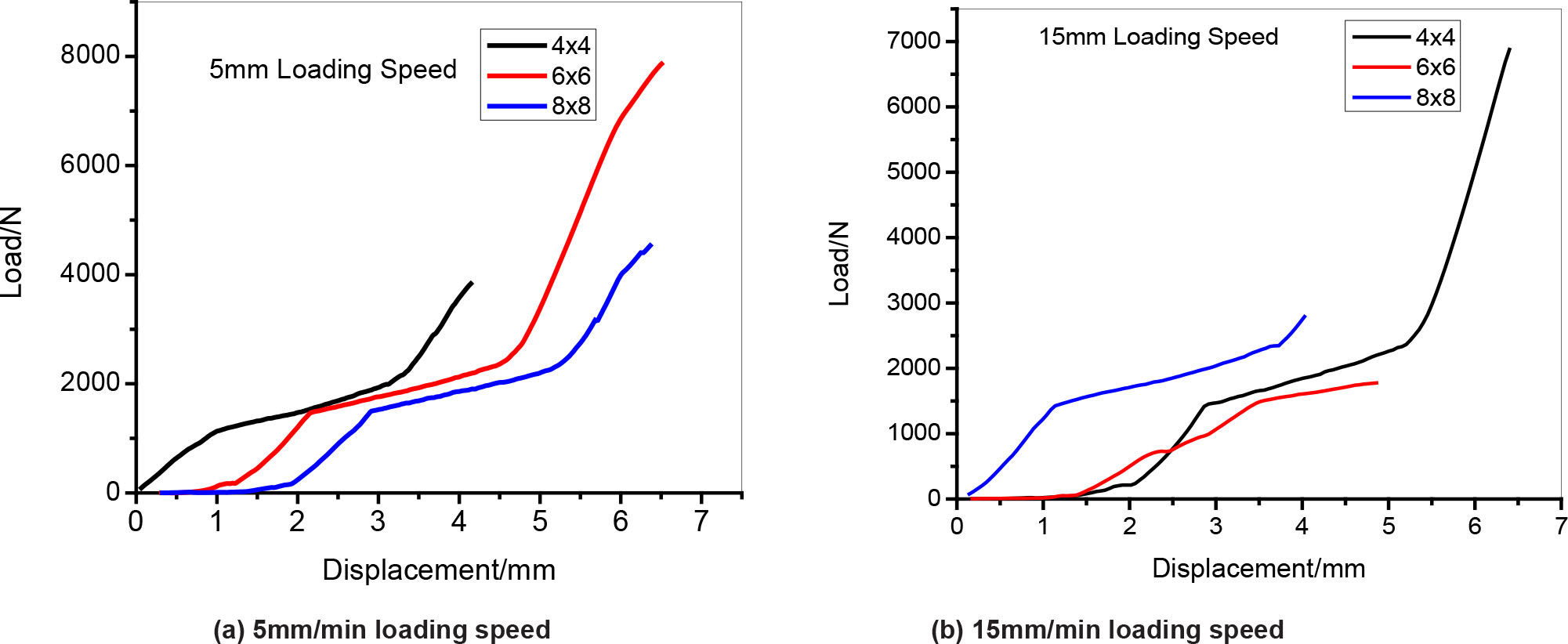
(a) Compression test and displacement curve under 5 mm/min loading speed. (b) Compression test and displacement curve under 15 mm/min loading speed
The 6 × 6 structure under the 5 mm/min loading speed had the highest peak of impact load with increasing displacement, followed by 8 × 8 structures and finally the 4 × 4 structure. However, the results experienced a reversal for the tests under 15 mm/min loading speed, with the 4 × 4 structure having the highest peak of impact load as well as displacement, followed by 8 × 8 structure as second to the 4 × 4 in impact load but lowest in displacement, and finally 6 × 6 structure having the lowest peak of load impact but second to 4 × 4 structure in displacement. This occurrence is presumed to be as a result of the change in the loading speed.
3.2 EA and composite’s response to crush analysis
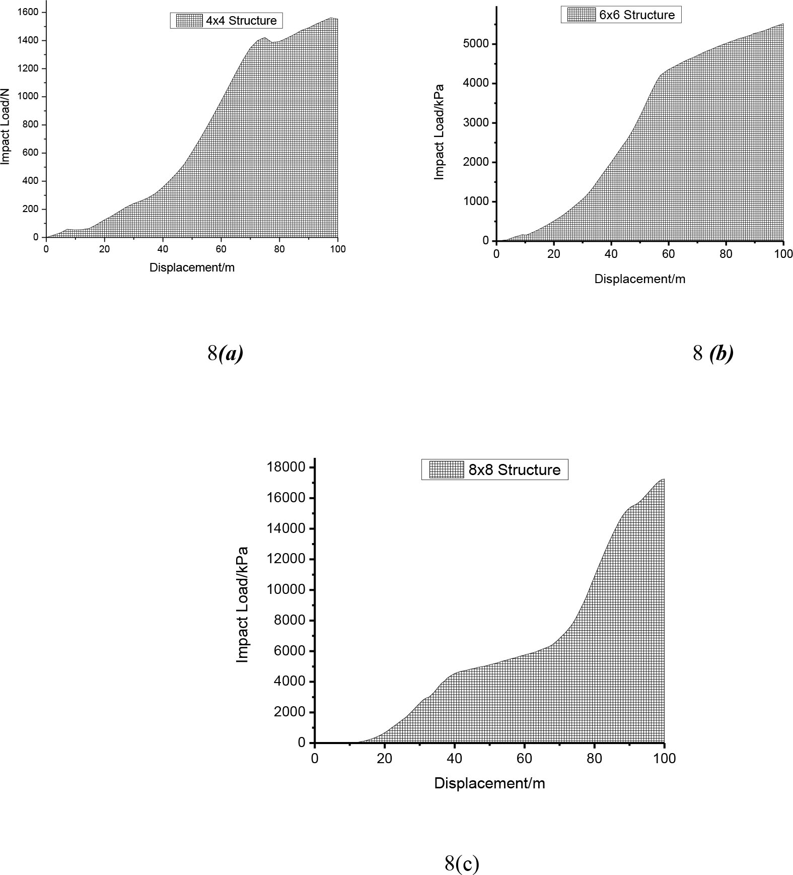
EA curves of the composite material with three different knitted structures and under two different impacts loading speeds are shown in Figures 7 and 8. The shaded areas under these curves represent the energy absorbed by the composite material under a quasi-static compression, and it is expressed as a function of impact load against displacement.
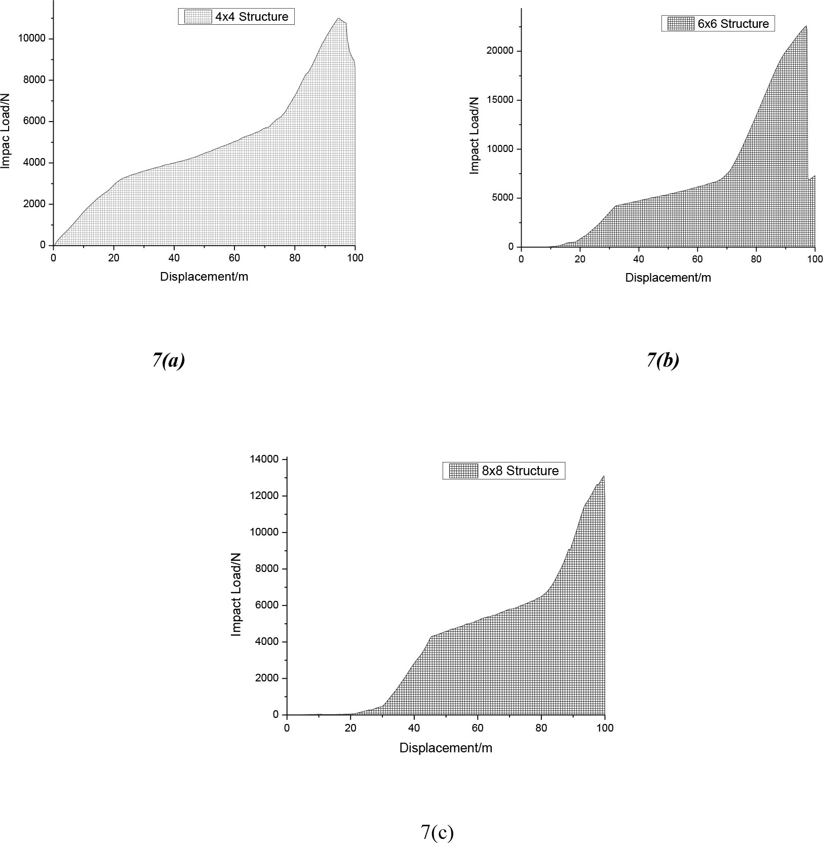
Energy absorption analysis of composite under 5 mm/min loading speed. (a) 4 × 4 structure, (b) 6 × 6 structure and (c) 8 × 8 structure
Energy absorption analysis of composite under 5 mm/min loading speed. (a) 4 × 4 structure, (b) 6 × 6 structure and (c) 8 × 8 structure
As shown clearly in Figure 7, under a 5 mm/min impact loading speed, the composite with 4 × 4 structure had a rapid increase in speed just after an impact initiation and continued till the failure of the composite with increase in displacement. Both the 6 × 6 and the 8 × 8 structural composites gradually increased after the impact initiation.
Under the 15 mm/min loading speed, the three structural composites recorded a gradual increase in impact load after initiating the impact force.
The EA performances of the structures are discussed in the paragraphs below. All values for the EA indicators employed in this study are represented in different charts as shown in Figure 9a–d, and for both 5 mm and 15 mm/min impact loading speed.
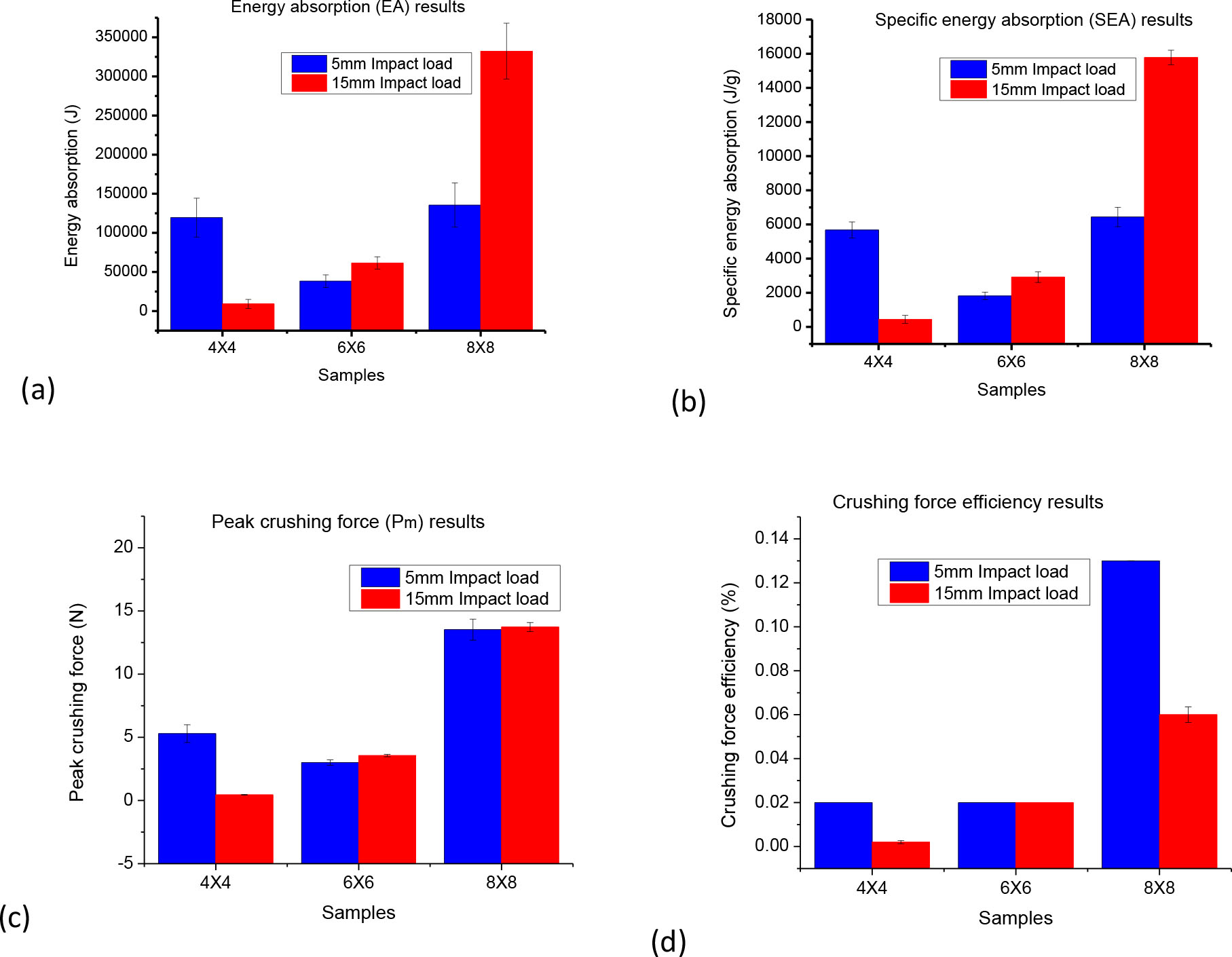
Energy absorption indicators of the composite material under 5 mm/min and 15 mm/min loading speed. (a) Energy absorption, (b) specific energy absorption, (c) peak crushing force and (d) crushing force efficiency
In Figure 9a, it is observed that the EA for samples tested under both impact loads were higher in the 8 × 8 structures followed by the 4 × 4 and finally the 6 × 6 structures. This EA ability of the structures increases with respect to the value of NPR present in the samples. The higher the NPR values in the composite, the greater the EA ability of the composite and vice versa. It can then be predicted that the composite structure’s ability to resist the force exerted on it is attributed to the NPR effect and it increases with increase in the NPR value, just as Yuping et al. [21] and Mohsenizadeh et al [14] propounded in their study.
From Figure 9b, it is seen that the SEA chart for samples tested under both 5 mm/min and 15 mm/min impact loading speed has a similar representation to the EA chart. This is because the mass of the samples tested were the same for the two different impact loads. However, studies have proven a tremendous enhancement in EA with increase in material NPR and density [14].
In Figure 9c, it is clearly seen that the Pm of the 8 × 8 structure is the greatest as compared to the other two structures. Followed by the 8 × 8 structure is the 4 × 4 structure under 5 mm/min impact loading and then the 6 × 6 structure sample. It can therefore be suggested that the structures with an auxetic effect can absorb significant energy under a given deformation.
Figure 9d depicts the CFE of the samples under both 5 mm/min and 15 mm/min impact loading speed. As clearly shown, the 8 × 8 structure has a greater crushing efficiency compared to the CFE of the remaining two structures. Nevertheless, it has been established that the NPR has a significant influence on the structures when they are subjected to a compressive force.
3.3 Damage morphology
When carefully observed, it can be seen that the damage of the composite materials for the two different impact loading speeds is directly reflected in their EA curves in Figures 7 and 8. During the quasi-static compression test for the three structures under both loading speeds, the damage began with a crack at a weak point and then migrates across the entire sample.
Throughout the test and damage morphology of the knitted composite, these observations were made, during the compression of the composites. There was first a matrix crack initiated in the resin zone, followed by a propagation of the cracks along the weak point within the sample, and then fiber-yarn breakage occurred along the trail of the cracks. Finally, the composite burst, contract or bulges [22]. Figures 10 and 11 show the damage for the composite samples tested under 5 mm/min and 15 mm/min loading speed, respectively.
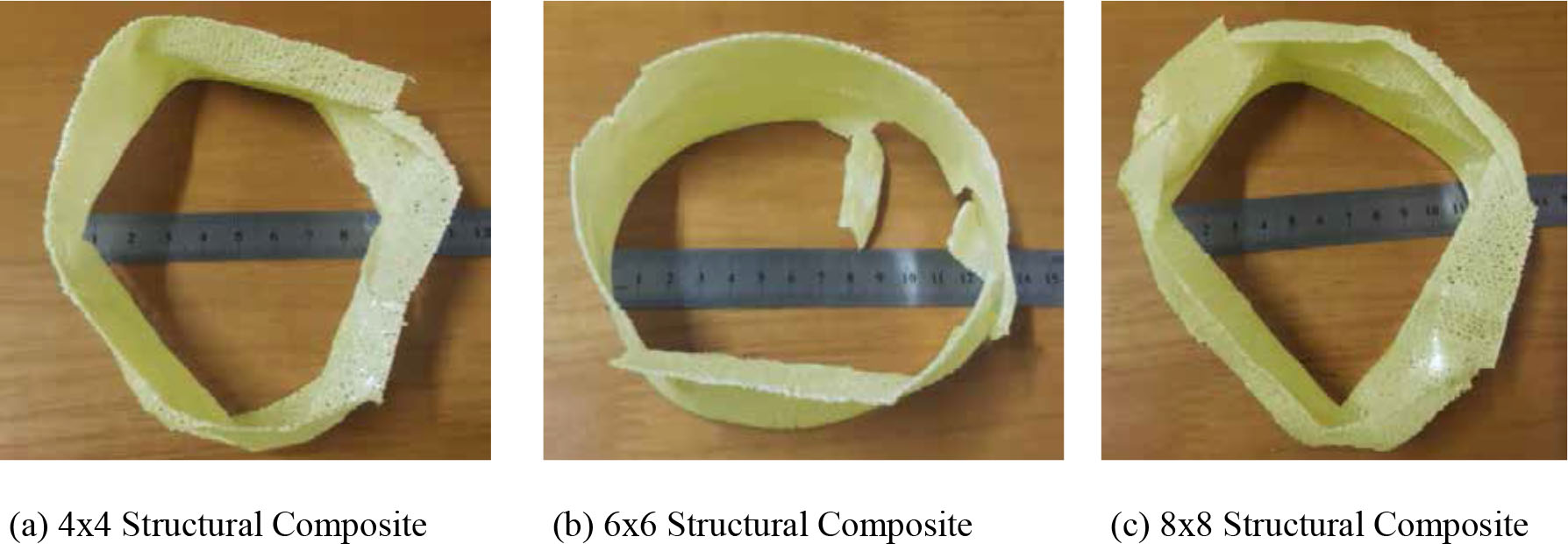
(a–c) Compression damage morphology of composite under 5 mm/min loading speed
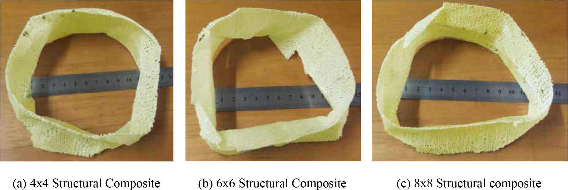
(a–c) Compression damage morphology of composite under 15 mm/min loading speed
4 Conclusions
The compressive property of a weft-knitted auxetic composite tube with three different knitted structures were tested via a quasi-static compression test. The results obtained from the test indicate that:
The EA ability of the composite tubes is greatly influenced by the auxetic properties inherent in the knitted structures. It was observed that the higher the value of the NPR, the higher and greater the composite’s ability to absorb more energy. This was reflected in the figures of the EA indicators. The 8 × 8 structure hand the highest EA. Even though experimentally 4 × 4 structures had the least NPR among the three structures, when compressed at 5 mm/min, its EA was higher than the 6 × 6 samples. There was however a linear relationship between NPR and EA of all three samples at 15 mm/min speed. The influence of NPR is thus more evident under high compression speed of 15 mm/min.
Apart from the individual NPRs of the knitted structures that influenced the EA property, the differences in their structural compactness had no effect on the composite tube and its compressive properties.
It was also noted that, during the fabrication of the composite material, positioning the mold vertical instead of making it rest flat on the support yielded a desirable tube devoid of resin residue. When the latter option was used, escaping resin residue hardened up and remained at the edges rendering the resultant product undesirable.
The damage inflicted on the composite tubes under quasi-static compression first went through a matrix crack initiated in the resin zone and then propagated along the weak point of the composite. This then was followed by fiber-yarn breakage along the trails of the cracks and finally it either bulged or contracted or exploded.
Acknowledgments
The authors acknowledge the financial support from the China Postdoctoral Science Foundation (2017T100325, 2016M591767), the Fundamental Research Funds for the Central Universities (JUSRP51625B), the Applied Foundation Research Funds of China Textile Industry Association (J201604), the Open Project Program of Laboratory of New Fiber Materials and Modern Textile, The Growing Base for State key Laboratory, Qingdao University (2017kfkt07) and the Open Project Program of Hubei Key Laboratory of Advanced Textile Materials & Application, Wuhan Textile University (Fzxcl2017013).
References
[1] Glazzard, M., Breedon, P. (2014). Weft-knitted auxetic textile design. Physica Status Solidi (b), 251(2), 267–272.10.1002/pssb.201384240Search in Google Scholar
[2] Boakye, A., Chang, Y., Raji Rafiu K., Ma P. (2017). Design and manufacture of knitted tubular fabric with auxetic effect. The Journal of The Textile Institute, 1–7.10.1080/00405000.2017.1361582Search in Google Scholar
[3] Hu, H., Wang, Z., Liu, S. (2011). Development of auxetic fabrics using flat knitting technology. Textile Research Journal, p. 0040517511404594.Search in Google Scholar
[4] Zhou, L., Jiang, L., Hu, H. (2016). Auxetic composites made of 3D textile structure and polyurethane foam. physica status solidi (b), 253(7): p. 1331–1341.10.1002/pssb.201552768Search in Google Scholar
[5] Rana, S., Magalhães, R., Fangueiro, R. (2017). Advanced auxetic fibrous structures and composites for industrial applications.Search in Google Scholar
[6] Jiang, N., Hu, H. (2017). A study of tubular braided structure with negative Poisson’s ratio behavior. Textile Research Journal, p. 0040517517732086.10.1177/0040517517732086Search in Google Scholar
[7] Wang, Z., Zulifqar, A., Hu, H. (2016). Auxetic composites in aerospace engineering. Advanced composite materials for aerospace engineering: Processing, properties and applications. Cambridge: Woodhead Publishing, pp. 213–240.10.1016/B978-0-08-100037-3.00007-9Search in Google Scholar
[8] Grima, J. N., Caruana-Gauci, R., Attard, D, Gatt, R. (2012). Three-dimensional cellular structures with negative Poisson’s ratio and negative compressibility properties. Proceedings of the Royal Society A: Mathematical, Physical and Engineering Science, 468(2146), 3121–3138.10.1098/rspa.2011.0667Search in Google Scholar
[9] Chang, Y., Ma, P., Jiang, G. (2017). Energy absorption property of warp-knitted spacer fabrics with negative Possion’s ratio under low velocity impact. Composite Structures, 182, 471–477.10.1016/j.compstruct.2017.09.065Search in Google Scholar
[10] Cabras, L., Brun, M. (2014). Auxetic two-dimensional lattices with Poisson’s ratio arbitrarily close to− 1. In Proceedings of the Royal Society of London A: Mathematical, Physical and Engineering Sciences. The Royal Society.10.1098/rspa.2014.0538Search in Google Scholar
[11] Rana, S., Fangueiro, R. (2016). Advanced composite materials for aerospace engineering: Processing, properties and applications. Woodhead Publishing.10.1016/B978-0-08-100037-3.00001-8Search in Google Scholar
[12] Mamalis, A.G., Robinson, M., Manolakos, D. E., Demosthenous, G. A., Ioannidis, M. B., Carruthers, J. (1997). Crashworthy capability of composite material structures. Composite Structures, 37(2), 109–134.10.1016/S0263-8223(97)80005-0Search in Google Scholar
[13] Harte, A.-M., Fleck, N. A., Ashby, M.F. (2000). Energy absorption of foam-filled circular tubes with braided composite walls. European journal of mechanics-A/Solids, 19(1), 31–50.10.1016/S0997-7538(00)00158-3Search in Google Scholar
[14] Mohsenizadeh, S., Alipour, R., Shokri Rad, M., Farokhi Nejad, A., Ahmad, Z. (2015). Crashworthiness assessment of auxetic foam-filled tube under quasi-static axial loading. Materials & Design, 88, 258–268.10.1016/j.matdes.2015.08.152Search in Google Scholar
[15] Jiang, L., Gu, B., Hu, H. (2016). Auxetic composite made with multilayer orthogonal structural reinforcement. Composite Structures, 135, 23–29.10.1016/j.compstruct.2015.08.110Search in Google Scholar
[16] Yoon, M.-K., Baidoo, J., Gillespie Jr, J. W., Heider, D. (2005). Vacuum Assisted Resin Transfer Molding (VARTM) Process Incorporating Gravitational Effects: A Closed-form Solution. Journal of Composite Materials, 39(24), 2227–2242.10.1177/0021998305053510Search in Google Scholar
[17] ASTM, D. (1999). Standard test method for void content of reinforced plastics. West Conshohocken (PA): ASTM International.Search in Google Scholar
[18] Boey, F., Lye, S. (1992). Void reduction in autoclave processing of thermoset composites: Part 1: High pressure effects on void reduction. Composites, 23(4), 261–265.10.1016/0010-4361(92)90186-XSearch in Google Scholar
[19] Liu, L., Zhang, B. -M., Wang, D. -F., Wu, Z. -J. (2006). Effects of cure cycles on void content and mechanical properties of composite laminates. Composite structures, 73(3), 303–309.10.1016/j.compstruct.2005.02.001Search in Google Scholar
[20] Schroeder, D. (2000). An Introduction to Thermal Physics. United States: Addison Wesley Longman.Search in Google Scholar
[21] Chang, Y., Ma, P., Jiang, G. (2017). Energy absorption property of warp-knitted spacer fabrics with negative Possion’s ratio under low velocity impact. Composite Structures.10.1016/j.compstruct.2017.09.065Search in Google Scholar
[22] Gideon, R. K., Zhou, H., Li, Y., Sun, B., Gu, B. (2016). Quasi-static compression and compression–compression fatigue characteristics of 3D braided carbon/epoxy tube. The Journal of The Textile Institute, 107(7), 938–948.10.1080/00405000.2015.1071964Search in Google Scholar
© 2020 Andrews Boakye et al., published by Sciendo
This work is licensed under the Creative Commons Attribution 4.0 International License.
Articles in the same Issue
- Compressive Property of an Auxetic-Knitted Composite Tube Under Quasi-Static Loading
- Investigation of the Tribological Behaviors of Upholstery Woven Fabrics after Abrasion
- Microstructural Damage Characteristic of a Layer-to-Layer Three-Dimensional Angle-Interlock Woven Composite Under Quasi-Static Tensile Loading
- Initial Investigation Into Real 3D Body Scanning Versus Avatars for the Virtual Fitting of Garments
- Mathematical Model Predicting the Heat and Power Dissipated in an Electro-Conductive Contact in a Hybrid Woven Fabric
- A Method of 1D UVC Radiation Dose Measurement using a Novel Tablet Dosimeter
- Introducing a Newly Developed Fabric for Air Filtration
- A New Approach to Evaluate Fabric Hand Based on Three-Dimensional Drape Model
- Study on the use of Aerogel on the Surface of Basalt Fabric
- Analysis of Factors Affecting Thermal Comfort Properties of Woven Compression Bandages
- Country-Specific Determinants of Textile Industry Development in Poland: Comparative Analysis of the Years 2007 and 2017
- Comparative Study of Needle Penetration Forces in Sewing Hems on Toweling Terry Fabrics: Influence of Needle Type and Size
- Numerical and Experimental Comparative Analysis of Ballistic Performance of Packages Made of Biaxial and Triaxial Kevlar 29 Fabrics
- Characterization of Fabric-to-Fabric Friction: Application to Medical Compression Bandages