Si⋯O proximity in imidosilanes – absence of orbital interactions
-
Marcus Herbig
 ,
Uwe Böhme
and
Edwin Kroke
,
Uwe Böhme
and
Edwin Kroke

Abstract
New N-silylated phthalimides, succinimides, and 1,8-napthalimides were synthesised by reactions of the alkali imides with chlorosilanes in THF. Six different mono-, di-, tri- and tetra-iminosilanes of the type (CH3)4–n Si(imide) n were obtained and the products analysed with 1H, 13C, 29Si NMR, and Raman spectroscopy. The molecular structures of four imidosilanes have been determined by single-crystal X-ray diffraction. A characteristic structural feature of the compounds is the fact that all intramolecular Si⋯O distances are significantly below the sum of the van-der-Waals radii of silicon and oxygen of 3.62 Å. Experimentally found values for Si⋯O distances range from 2.813 to 3.030 Å. However, there are no significant orbital interactions between silicon and oxygen atoms, as shown by quantum chemical analysis with AIM and NBO methods. The short Si⋯O distances in these molecules are caused by the geometry of the rigid imide group bound to the silicon atom, and there is no evidence for an increase of the coordination number of the Si atoms.
1 Introduction
Cyclic imides (A in Figure 1) derived from dicarboxylic acids are a versatile class of compounds [1]. Acyclic imides are prone to decomposition into nitriles and carboxylic acids [1, 2]. Imide subunits are components of drugs, fungicides and herbicides [3, 4]. Polyimides show unique properties like high dielectric and mechanical strength (e. g. tensile and compressive strength), thermal stability and chemical inertness [5].

General representation of cyclic imides (A, R = H, Alkyl, Aryl) and imidosilanes (B, R = H, Alkyl, Aryl, imides).
The silylation of cyclic imides, i.e. the synthesis of imidosilanes (B in Figure 1), can be accomplished starting with the imides, a chlorosilane and a base (e. g. triethylamine) [6], [7], [8] at ambient temperatures. Due to the easy accessibility of the alkali salts of imides, often the reaction of chlorosilanes with sodium or potassium imidates is used for the synthesis [6, 9], [10], [11]. With this synthesis method, more than one imido substituent can be attached to a silicon atom [10]. Trimethylsilylation of imides with HMDS (1,1,1,3,3,3-hexamethyldisilazane) can be performed without catalysts [12, 13] or with trimethylsilyldimesylamine (N‐methanesulfonyl‐N‐(trimethylsilyl)-methanesulfonamide) [14] or saccharin as catalysts [15]. Even carboxylic anhydrides react with HMDS at temperatures above 100 °C to form trimethylsilylated imides [12, 13]. Reactions of carboxylic anhydrides with HMDS can also effectively lead to the imides, depending on the synthesis parameters [16]. Other silylation reagents suitable for the synthesis of imidomonosilanes are BSA (N,O-bis(trimethylsilylacetamide)) [17] and ketenketyl-tert-butylsilylacetal [18, 19]. N-chlorosuccinimide can also be trimethylsilylated using BSA [20, 21] with N-chloro-O-trimethylsilylacetamide as by-product. Disilanes are converted into imidosilanes and halosilanes by the reaction with N-bromosuccinimide [22]. The substitution of alkoxy moieties with imide moieties on a silicon atom is also possible [23].
Some applications of imidosilanes have been proposed but seem to be restricted to special fields: phthalimidosilanes have been used for the design of fuel cells [24], for improving the flame retarding properties of organic polymers [25], and in pharmaceutical compositions for the treatment of inflammations, tumors, and psoriasis [26]. Silicon-substituted imides of dicarboxylic acids have been employed as resist materials which have promising properties, such as low optical absorption in the deep UV region, good thermal stability, and improved adhesion to silicon substrates [27, 28]. Furthermore, silicon containing imides have been proposed (among other silicon containing compounds) as organic electrolyte solvents in high-energy density secondary batteries. The electrolytes are resistant to fire, have good wettability for electrodes, and improve the safety of the batteries [29].
The structural properties of imidosilanes are mainly unexplored. Only a few crystal structures have been reported [6, 8, 30], [31], [32].
We set out to prepare and structurally characterise selected imidosilanes. This is in line with our continuing work about different types of silicon-nitrogen compounds like amides [33], [34], [35], carbodiimides [36], [37], [38], [39], [40], silazanes [41], [42], [43], [44], [45], salen complexes [46], [47], [48], spirosilanes [49], and lactamomethylsilanes [50]. The Si–N bonds present in compounds of type B can be subjected to interesting reactions like the insertion of heteroallenes like CO2 and isocyanates [51], [52], [53], [54]. Here we report the synthesis and properties of six mono-, di-, tri- and tetra-imido monosilanes and their spectroscopic characterisation and structural analysis.
2 Results and discussion
2.1 Synthesis
For the synthesis of compounds containing more than one imide moiety per silicon atom, a route starting with chlorosilanes is preferable. This offers the best access to imidosilanes with more than one imido substituent attached to a silicon atom (see Figure 2).

Synthesis routes of the prepared imidosilanes.
Imidosilanes of the type (CH3)4–n Si(imide) n with more than one Si–N bond are only slightly soluble in organic solvents. Other reactions failed to give the expected products. To give an example, the reaction mixture of dichlorodimethylsilane and succinimide with triethylamine as HCl scavenger in THF under reflux turned black, and no product could be identified.
For compound 1, the results of synthesis trials using different solvents and reaction temperatures were compared. The product with highest purity and yield can be obtained in THF at room temperature. Heating the reaction mixture in THF to reflux decreases the reaction time but also the product purity and yield.
Acyclic imides are prone to decomposition. For example, N-benzoylbenzamide decomposes to benzonitrile and benzoic acid [1, 2]. N-silylation facilitates this decomposition because the Si–O bond in the formed silylated carboxylic acid is more stable than the Si–N bond in the imidosilane. For this reason no silylated imide could be isolated in all attempts of the silylation of diacetamide.
The six new imidomonosilanes prepared in the present work are shown in Figure 3. These are derived from phthalimide, succinimide, and 1,8-napthalimide.

Imidosilanes prepared in this work. The imido moieties are phthalimide (1–3), succinimide (4, 5) and 1,8-naphthalimide (6).
2.2 Spectroscopic data
The compounds 1 to 6 were analysed by 1H, 13C and 29Si NMR, and Raman spectroscopy (see Experimental Part). A comparison of the 29Si NMR chemical shifts of imidosilanes and aminosilanes (see Table 1) shows that the signals are at lower field for imides of the type Me3SiR and Me2SiR2, while the MeSiR3 imides show chemical shifts similar to those of the corresponding aminosilanes. The Si nucleus in Si(phthalimide)4 (3) is more shielded than in Si(pyrrolidine)4.
29Si NMR chemical shift of some imidosilanes in comparison with that of similar aminosilanes derived from pyrrolidine.
| R | Me3SiR | Me2SiR2 | MeSiR3 | SiR4 |
|---|---|---|---|---|
| Pyrrolidine | 2.5 [55] | −8.1 [50] | −24.6 [50] | −43.3 [50] |
| Phthalimide | 13.0 [56]; 12.7 [57] | 2.6 (comp. 1) | −24.3 (comp. 2) | −58.2 (comp. 3) |
| Succinimide | 13.0 [6]; 13.4 [57] | 4.6 (comp. 4) | −23.9 (comp. 5) | – |
| 1,8-Naphthalimide | 16.5 (comp. 6) | – | – | – |
| Glutarimide | 13.8 [6] | – | – | – |
Regarding the electronic characteristics of Si–N bonds, a π interaction of empty σ* and/or d orbitals at the silicon atom with the lone pair of the nitrogen atom was discussed (e. g. [58, 59]). However, in an imide moiety the nitrogen centred lone pair is part of a conjugated π system including the two carbonyl units.
In the Raman spectra of the solids, the typical imide C=O stretching vibration [60] is observed at around 1761 cm−1 for compounds 1 to 5 and at 1698 cm−1 for compound 6. A strong band between 1690 and 1640 cm−1 caused by a C=N double bond is not found. Therefore, the presence of O-silylated isomers [6] can be excluded for compounds 1 to 6 in the solid state at room temperature. This is supported by the crystal structures of 1, 3, 4, and 6 (vide infra).
2.3 Molecular structures
Compound 1 crystallises in the triclinic space group

Molecular structure of one crystallographically independent molecule of 1 including the numbering scheme. The displacement ellipsoids of non-hydrogen atoms are drawn at the 50% probability level.
Selected geometric parameters (Å, deg) of 1 and 3.
| 1 | 3 | ||
|---|---|---|---|
| Si1–N2A | 1.770(1) | Si1–N1 | 1.736(2) |
| Si1–N1A | 1.784(1) | ||
| Si1–C18A | 1.844(1) | ||
| Si1–C17A | 1.848(1) | ||
| Si1⋯O1A | 3.030(1) | Si1⋯O1 | 2.955(2) |
| Si1⋯O2A | 3.297(1) | Si1⋯O2 | 3.296 (2) |
| Si1⋯O3A | 3.164(1) | ||
| Si1⋯O4A | 3.160(1) | ||
| N2A–Si1–N1A | 103.84(5) | N1–Si1–N1#1 | 107.7(1) |
| N2A–Si1–C18A | 110.10(5) | N1–Si1–N1#2 | 110.38(6) |
| N1A–Si1–C18A | 110.00(5) | N1#1–Si1–N1#2 | 110.38(6) |
| N2A–Si1–C17A | 110.91(6) | N1–Si1–N1#3 | 110.38(6) |
| N1A–Si1–C17A | 110.43(6) | N1#1–Si1–N1#3 | 110.38(6) |
| C18A–Si1–C17A | 111.31(6) | N1#2–Si1–N1#3 | 107.7(1) |
| C1A–N1A–C8A | 109.51(9) | C1–N1–C8 | 109.6(2) |
| C1A–N1A–Si1 | 120.42(8) | C1–N1–Si1 | 118.5(1) |
| C8A–N1A–Si1 | 130.03(8) | C8–N1–Si1 | 131.7(2) |
| C9A–N2A–C16A | 109.2(1) | ||
| C9A–N2A–Si1 | 124.78(8) | ||
| C16A–N2A–Si1 | 124.53(8) | ||
-
Symmetry transformations used to generate equivalent atoms: #1 –x + 0, –y + 1/2, z + 0; #2 y – 1/4, –x + 1/4, –z + 1/4; #3 –y + 1/4, x + 1/4, –z + 1/4.
Compound 3 crystallises in the tetragonal space group I41/a with a quarter of the molecule in the asymmetric unit. The molecular structure is shown in Figure 5, and selected geometric parameters are presented in Table 2. The silicon atom is located on a special position. The four organic groups are generated by an inversion axis (symbol
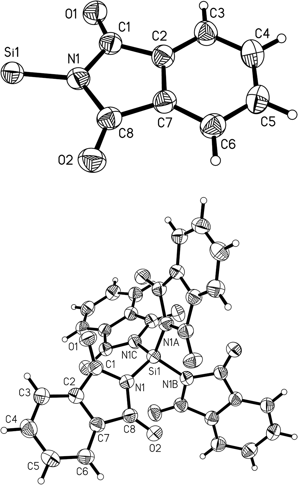
Asymmetric unit of compound 3 including the numbering scheme (top) and molecular structure of 3 (bottom). The displacement ellipsoids of non-hydrogen atoms are drawn at the 50% probability level.
A closer inspection of the bond angles shows that there is a considerable deformation of the exocyclic C–N–Si angles. In compound 1 the angle C1A–N1A–Si1 is found at 120.42(8)° as expected, but the angle C8A–N1A–Si1 is much larger at 130.03(8)°. This difference of nearly 10° leads to a short distance of 3.030(1) Å between Si1 and O1A. The exocyclic C–N–Si bond angles of the other phthalimide group in 1 are nearly equal and do not feature such a bending of the imide substituent. However, all Si–O distances in 1 are below the sum of the van-der-Waals radii of silicon and oxygen of 3.62 Å [r(Si) = 2.10 Å, r(O) = 1.52 Å] [61]. Therefore, possible Si⋯O interactions will be discussed below.
The same type of bending of a phthalimide ligand at silicon has been observed in the crystal structure of N-trimethylsilylphthalimide [8]. The crystal structure of compound 3 shows also a bending of the phthalimide ligand. The difference between the exocyclic angles is even larger, i.e. about 13° between the bond angles C1–N1–Si1 118.5(1)° and C8–N1–Si1 131.7(2)°. The silicon atom in 3 is in perfect tetrahedral coordination geometry due to crystallographic symmetry. The short distance Si1⋯O1 of 2.955(2) Å in molecule 3 is reproduced four times by the symmetry of the molecule.
Compound 4 crystallises in the monoclinic space group C2/c. The asymmetric unit contains one molecule of 4 and half a molecule of benzene around a special position. The benzene molecule is rotationally disordered (see Supplementary material). The molecular structure is shown in Figure 6, selected geometric parameters are listed in Table 3. The five-membered ring of the succinimide group N1–C1–C2–C3–C4 is in envelope conformation with the nitrogen atom bent out of the plane of the other four atoms, while the group N2–C5–C6–C7–C8 is planar. The silicon nitrogen bond lengths of 1.771(2) and 1.787(1) Å are in the same range as in 1 (see Table 3). The nitrogen atom N1 with a sum of bond angles of 358.4(2)° is slightly less planarised than N2 with 359.6(2)° [59].

Molecular structure of 4 including the numbering scheme. The displacement ellipsoids of non-hydrogen atoms are drawn at the 50% probability level.
Selected geometric parameters (Å, deg) of 4.
| Si1–N1 | 1.771(2) |
| Si1–N2 | 1.787(1) |
| Si1–C10 | 1.836(2) |
| Si1–C9 | 1.837(2) |
| Si1⋯O1 | 3.114(2) |
| Si1⋯O2 | 3.097(2) |
| Si1⋯O3 | 2.963(1) |
| Si1⋯O4 | 3.277(1) |
| N1–Si1–N2 | 103.63(6) |
| N1–Si1–C10 | 110.05(9) |
| N2–Si1–C10 | 110.55(8) |
| N1–Si1–C9 | 110.98(8) |
| N2–Si1–C9 | 109.52(8) |
| C10–Si1–C9 | 111.8(1) |
| C4–N1–C1 | 109.7(2) |
| C4–N1–Si1 | 124.1(1) |
| C1–N1–Si1 | 124.6(1) |
| C5–N2–C8 | 110.8(1) |
| C5–N2–Si1 | 118.4(1) |
| C8–N2–Si1 | 130.4(1) |
The imide units are again bent away from the Si–N axis, i.e. the C–N–Si angles at the nitrogen atom N2 show a difference of 12° (Table 3). This distortion allows the oxygen atom O3 to get in close contact with the silicon atom [Si1⋯O3 = 2.963(1) Å]. The other imide unit with nitrogen atom N1 shows equal C–N–Si angles.
Compound 6 crystallises in the monoclinic space group P21/c with one molecule in the asymmetric unit. The molecular structure is shown in Figure 7, selected geometric parameters are presented in Table 4. The imide unit is completely planar as expected. The silicon nitrogen bond is longer than in the other three compounds [1.823(2) Å]. The nitrogen atom is planarised with a sum of bond angles of 359.9(2)°, and all silicon carbon bonds are in the normal range of about 1.86(2) Å for Si–C(sp 3) bonds [59]: The imide unit is again bent away from the Si–N axis with the two C–N–Si angles showing a difference of 8.4° (Table 4). This distortion allows the oxygen atom O1 to get in close contact with the silicon atom [Si1⋯O1 = 2.813(2) Å].

Molecular structure of 6 including the numbering scheme. The displacement ellipsoids of non-hydrogen atoms are drawn at the 50% probability level.
Selected geometric parameters (Å, deg) of 6.
| Si1–N1 | 1.823(2) |
| Si1–C14 | 1.852(2) |
| Si1–C15 | 1.852(2) |
| Si1–C13 | 1.856(2) |
| Si1⋯O1 | 2.813(2) |
| Si1⋯O2 | 3.057(2) |
| N1–Si1–C14 | 107.04(9) |
| N1–Si1–C15 | 111.41(9) |
| C14–Si1–C15 | 109.9(1) |
| C14–Si1–C13 | 114.3(1) |
| C15–Si1–C13 | 106.5(1) |
| C1–N1–C12 | 122.1(2) |
| C1–N1–Si1 | 114.7(1) |
| C12–N1–Si1 | 123.1(1) |
3 Investigation of the short Si⋯O distances
The Si⋯O distances in the molecular structures of 1, 3, 4, and 6 are below the sum of the van-der-Waals radii. Furthermore, a bending of the imide moieties away from the Si–N axis was observed. This leads to the effect that certain oxygen atoms are significantly closer to the silicon atom than the other one of the same imide moiety. Therefrom the question arises, whether these short distances are due to Si⋯O interactions. It is well known that silicon is able to form penta- and hexacoordinate compounds depending on the nature of the substituents [62, 63].
Quantum chemical calculations were performed in order to examine the nature of possible Si⋯O interactions in these molecules. The compounds 4 and 6 have been selected as representative examples for the theoretical investigations.
The topology of the electron density distribution in 4 and 6 has been investigated with the quantum theory of atoms in molecules (QTAIM) which was developed by Bader and others [64], [65], [66], [67], [68], [69]. The following facts should be kept in mind, when reading this section: Saddle points with a maximum in two dimensions and a minimum in one dimension are called bond critical points (BCP). When a BCP is found between two atoms an atomic interaction line can be drawn. When the molecule is in equilibrium geometry, the atomic interaction line is called a bond path. A bond path is not identical with a bond in the sense used by a Lewis structure. A bond path is observed for ionic bonds, covalent bonds, weak hydrogen bonds and even interactions between anions [70].
Graphical representations of the calculated topology of 4 and 6 are shown in Figure 8. This topology is also found in the crystal structure. A closer look on both figures reveals some surprising features: In compound 4 there are bond paths between one of the succinimide unit and the neighbouring methyl groups and one bond path between its nitrogen atom with a neighbouring oxygen atom. However, there are no bond paths between any of the four oxygen atoms and the silicon atom! In compound 6, there is a bond path between one oxygen atom and a carbon atom of a methyl group in cisoid conformation, but again there are no bond paths between oxygen and silicon atoms.

Calculated molecular graphs of 4 (top) and 6 (bottom) with critical points. Bond critical points (BCP) are red, ring critical points yellow, atomic spheres are drawn with arbitrary radii (atom colours: silicon – dark grey, carbon – black, nitrogen – blue, oxygen – red, hydrogen – light grey).
The nature of the interactions indicated by the bond paths can be analyzed with the numerical values shown in Table 5 and the graphical representation of the Laplacian of the electron density given in Figure 9. Selected bonds will be discussed in the following. The silicon nitrogen bonds in 4 and 6 have rather low electron densities at the bond critical points around 0.1 e Bohr−3 and positive values of the Laplacian of electron density (∇2 ρ). The graphical representation in Figure 9 (bottom) shows accumulation of charge at the electronegative nitrogen in the N–Si bond. A closer inspection of these bonds is possible with the total energy density (H) and the ratio of the kinetic energy density to electron density (G/ρ). For both bonds H has small negative values and G/ρ > 1. According to the criteria proposed by Macchi et al. [71] these bonds should be considered as polar shared bonds. This goes in line with findings of Kocher et al. who found highly polar Si–N bonds with remarkable ionic contributions from experimental charge density studies on tetracoordinated organosilicon compounds [72].
Charge density (ρ), its Laplacian (∇2 ρ), kinetic energy density (G), electronic potential energy density (V), and total energy density (H) at bond critical points (BCP) in atomic units for compounds 4 and 6.
| ρ | ∇2 ρ | G | G/ρ | H | V | |
|---|---|---|---|---|---|---|
| Compound 4 | ||||||
| Si1–N2 | 0.108 | 0.462 | 0.160 | 1.488 | −0.045 | −0.205 |
| N2–C5 | 0.298 | −0.839 | 0.175 | 0.587 | −0.385 | −0.560 |
| C5–O3 | 0.414 | −0.039 | 0.693 | 1.672 | −0.703 | −1.396 |
| O4⋯N1 | 0.015 | 0.053 | 0.012 | 0.814 | 0.001 | −0.011 |
| O1⋯C9 | 0.011 | 0.039 | 0.009 | 0.812 | 0.001 | −0.007 |
| O2⋯H10 | 0.010 | 0.034 | 0.007 | 0.753 | 0.001 | −0.006 |
| Compound 6 | ||||||
| Si1–N1 | 0.100 | 0.403 | 0.141 | 1.411 | −0.040 | −0.181 |
| N1–C1 | 0.295 | −0.839 | 0.163 | 0.553 | −0.373 | −0.537 |
| C1–O1 | 0.408 | −0.104 | 0.661 | 1.622 | −0.687 | −1.348 |
| O2⋯C15 | 0.014 | 0.053 | 0.012 | 0.862 | 0.002 | −0.010 |

Electron density (top) and Laplacian of the electron density of 4 (bottom) in the Si–C–N–O plane. Positive values of ∇2 ρ are drawn with dashed lines and represent regions of charge depletion; negative values are drawn with solid lines and represent regions of charge concentration. Contour values in atomic units are: 0.001, 0.002, 0.004, 0.008, 0.02, 0.04, 0.08, 0.2, 0.4, 0.8, 2, 4, 8, 20, 40, 80, 200, 400, 800. Areas of valence shell charge concentration (VSCC) of the oxygen atom are marked in blue.
The N–C bonds in 4 and 6 have higher electron density at the bond critical points (0.295–0.298 e Bohr−3) and negative values the Laplacian of electron density (∇2 ρ). These bonds are covalent. This is also reflected in the accumulation of electron density between nitrogen and carbon in Figure 9 (bottom).
Even higher values of electron density around 0.41 e Bohr−3 are found for the C=O bonds in 4 and 6. These are combined with small negative values for the Laplacian of electron density (∇2 ρ), negative values for H, and G/ρ > 1. The C=O bonds should therefore be considered as polar shared bonds [71].
The unexpected interactions O4⋯N1, O1⋯C9, O2⋯H10 in compound 4, and O2⋯C15 in compound 6 show low electron density at the bond critical point between these atoms. Values are in the range from 0.010 to 0.015 e Bohr−3. This is one order lower in magnitude than for the Si–N bonds discussed above and indicates rather weak interactions between the atoms involved. The Laplacian of electron density (∇2 ρ) has small positive values, the potential energy density V is negative, G has a similar value as the absolute value of V, H is positive and close to zero. These data let us qualify these interactions as poor intramolecular contacts [73].
The atomic charges have been calculated from NBO analyses of 4 and 6 and are shown in Table 6. These natural charges support the qualitative picture drawn in Figure 9 Plots of the electrostatic potentials mapped on the van-der-Waals surface of the molecules are shown in the Supplementary material available online.
Selected natural charges in 4 and 6.
| Compound 4 | Natural charge | Compound 6 | Natural charge |
|---|---|---|---|
| Si1 | 1.99 | Si1 | 1.80 |
| N2 | −0.91 | N1 | −0.86 |
| C5 | 0.74 | C1 | 0.72 |
| O3 | −0.60 | O1 | −0.61 |
It is possible to rationalise the close Si⋯O distances in these imidosilane by simple steric arguments. Figure 10 visualises the situation in these imidosilanes. The resulting Si⋯O distance is 3.050 Å, meaning that both atoms are not drawn together.
![Figure 10:
Geometrical sketch of the bonding situation in imidosilanes with idealised bond lengths and angles (Si–N bond length from ref. [59], N–C and C=O bond lengths from ref. [74]).](/document/doi/10.1515/znb-2021-0118/asset/graphic/j_znb-2021-0118_fig_010.jpg)
The variations of the Si–N–C bond angles in the crystal structures therefore is not a result of attractive forces between Si and O atoms but rather the result of steric interactions within the molecules. This situation is visualised for compound 4 in Figure 11.

Sketch of the steric interactions in 4 leading to angle tilt and a short Si⋯O distance.
The Si⋯O proximity in similar compounds has been discussed by Szalay et al. [8] as interactions including a second coordination sphere around the silicon atom on the way to higher coordination. The same type of distortion has been observed in the crystal structure of N-(dimethylsuccinimidosilylmethyl)succinimide [6]. Furthermore, these authors were able to show that with glutarimide a truly pentacoordinate silicon complex can be obtained. The more relaxed geometry of the aliphatic six membered ring of glutarimide allows to form a short O–Si of 2.17 Å in N-(chlorodimethylsilylmethyl)glutarimide [6].
Short Si⋯O distances have also been observed in spirocyclic aminosilanes with lateral p-toluenesulfonyl groups [75, 76] and in lactamosilanes [77]. However, all claims about higher coordination by additional Si⋯O contacts made so far in the literature [8, 75, 76] must be treated with reservation until firm evidence can be provided.
4 Conclusions
The imidomonosilanes 1–6 were synthesised by reactions of the alkali imides with chlorosilanes in THF at room temperature. At higher temperatures side products are formed. The crystal structures of the compounds 1, 3, 4, and 6 show a bending of the imido groups away from the Si–N axis and surprisingly short Si⋯O distances well below the sum of the van-der-Waals radii in all cases. The question arises whether Si⋯O orbital interactions are present. This question was answered with results of quantum chemical methods: no bond-critical points are found between the Si and O atoms indicating the absence of any significant electronic interactions. However, attractive Coulomb interactions can be assumed, due to the partial charges on the silicon and oxygen atoms. Summarizing the findings from crystal structures and quantum chemical analysis it can be concluded that the short Si⋯O distances found in these molecules arise from steric congestion owing the structural preference of the atom sequence Si–N–C=O.
5 Experimental section
All reactions were carried out under argon using standard Schlenk technique [78, 79]. Used chemicals and purification methods can be found in the Supplementary material. NMR spectra were recorded in CDCl3 or C6D6 with TMS as internal standard either on a BRUKER DPX 400 spectrometer at 400.13, 100.61 and 79.49 MHz for 1H, 13C and 29Si NMR spectra or on a BRUKER AVANCE III 500 MHz spectrometer at 500.13, 125.76 and 99.36 MHz for 1H, 13C and 29Si NMR spectra, respectively. Raman spectra were measured with a FT-Raman spectrometer RFS/100S from BRUKER using a air-cooled Nd:YAG-laser with a wavelength of 1064 nm and a nitrogen-cooled germanium detector. Melting points were measured using a Polytherm A hot stage microscope from Wagner and Munz with an attached 52II thermometer from Fluke. Mass spectra were recorded on an expressionL CMS instrument from Advion using ESI (MeCN as eluent).
5.1 Quantum chemical calculations
The quantum chemical calculations have been performed with Gaussian 16 [80]. The molecules 4 and 6 have been optimised with M062X/6-311+G(d,p) [81], [82], [83], [84]. The calculation of Hessian matrices verified the presence of local minima on the potential energy surface with zero imaginary frequencies. NBO and AIM analyses have been performed with the optimised geometries. NBO analyses have been performed with NBO 6.0 [85]. The wavefunction files for the QTAIM analysis were generated in Cartesian coordinates with a basis set containing 6d functions (option “6D 10F” in Gaussian 16). The electron density topology was analyzed using the programs AIM2000 [86] and Xaim [87]. File formats were converted with Open Babel [88].
5.2 Diacetamide
Diacetamide was synthesised using a modified procedure of Polya and Tardrew [89]. Through a solution of acetamide (30.00 g, 0.51 mol) in acetic anhydride (64.51 g, 0.63 mol) was bubbled HCl gas (from the reaction of sodium chloride with conc. sulfuric acid) for 25 min. The resulting suspension was refluxed for 30 min and afterwards the volatiles were distilled at ambient pressure, the residue at reduced pressure. The solid product, distilled at 87 °C (1.3 mbar), was dissolved in diethyl ether (350 mL) and once again HCl gas was passed through the solution. The resulting suspension was filtrated and to the filtrate were added barium carbonate (5.0 g) and afterwards potassium carbonate (5.0 g). The suspension was stirred overnight. After filtration volatiles were removed in vacuo yielding 29.08 g (57%) of a colourless solid. 1H NMR (400 MHz, CDCl3): δ = 2.32 (s, 6 H, CH3), 9.55 (br, 1 H, NH). – 13C NMR (100 MHz, CDCl3): δ = 25.0 (CH3), 172.3 (C=O).
5.3 Potassium-phthalimide
Potassium-phthalimide was synthesised using a modified procedure of Salzberg and Supniewski [90]. Phthalimide (80 g, 0.54 mol) was dissolved in hot abs. ethanol (1.6 L). The hot solution was decanted into a solution of potassium hydroxide (30.50 g, 0.54 mol) in abs. ethanol. The suspension was filtrated in water jet vacuum and washed with acetone (200 mL). The pale yellow, pearlescent solid was dried in a desiccator over silica gel.
5.4 Sodium-succinimide
To a suspension of succinimide (20.00 g, 0.20 mol) in abs. methanol (40 mL) was added a solution of sodium methoxide in methanol (25%, 43.73 g solution, 0.20 mol NaOMe). Volatiles were removed in vacuum and the residue was washed with diethyl ether.
5.5 Potassium-naphthalimide
Potassium hydroxide (10.00 g, 0.18 mol) was dissolved in abs. ethanol (200 mL). To the solution was added 1,8-naphthalimide (10.00 g, 0.05 mol) and the suspension was heated in a water bath for 1 h. The solid was filtered and dried in a desiccator over silica gel.
5.6 General procedure for the synthesis of imidosilanes giving 1 as example
Potassium-phthalimide (5.00 g, 27 mmol) was suspended in THF (60 mL) and dimethyldichlorosilane (1.17 g, 9.1 mmol) was added dropwise. The reaction mixture was stirred at room temperature overnight. Afterwards the mixture was filtered and volatiles were removed in vacuum yielding 1.92 g of a white solid. The synthesis of 1 was optimised as described in Table 7. Mp: 147 °C (decomp.). – 1H NMR (500 MHz, CDCl3): δ = 0.98 (s, 6 H, Si–CH3), 7.71 (dd, J = 5.5 and 3.0 Hz, 4 H, o-Ar), 7.81 (dd, J = 5.5 and 3.1 Hz, 4 H, m-Ar). – 13C NMR (125 MHz, CDCl3): δ = −0.4 (Si–CH3), 123.6 (o-Ar), 134.0 (i-Ar), 134.4 (m-Ar), 172.7(C=O). – 29Si NMR (99 MHz, CDCl3): δ = 2.6. – Raman: ν = 3084 (m), 3061 (vs), 3032 (w), 3007 (vw), 2974 (w), 2913 (s), 1779 (s), 1761 (vs), 1713 (vw), 1696 (vw), 1609 (s), 1468 (vw), 1364 (w), 1345 (vw), 1306 (w), 1293 (vw), 1169 (vs), 1158 (w), 1077 (vw), 1011 (vs), 872 (vw), 709 (vw), 691 (w), 664 (vs), 577 (w), 373 (vw), 354 (w), 329 (vw), 298 (vw), 259 (w), 232 (w), 205 (vw), 182 (m), 147 (m), 118 (m), 97 (w) cm−1. – MS: m/z = 433.227([M + 2 MeCN + H]+).
Batches for the optimisation of the synthesis of 1.
| Batch No. | K-phthalimide | Me2SiCl2 | Solvent | Procedure | Yield and purity |
|---|---|---|---|---|---|
| 1 | 10.01 g (54 mmol) | 3.39 g (26 mmol) | 50 mL THF | Reflux (1 h) | 8.05 g (87%) not pure |
| 2 | 10.00 g (54 mmol) | 3.40 g (26 mmol) | 60 mL THF | Reflux (2 h) | 7.27 g (79%) purity worse than no. 1 |
| 3 | 5.00 g (27 mmol) | 1.60 g (12 mmol) | 60 mL THF | Reflux (1.5 h) | 3.18 g (73%) low purity |
| 4 | 5.00 g (27 mmol) | 1.52 g (12 mmol) | 60 mL acetonitril | Reflux (1.5 h) | 1.74 g (42%) not pure |
| 5 | 5.00 g (27 mmol) | 1.58 g (12 mmol) | 60 mL diethylether | Reflux (1 h) | 0.90 g (21%) not pure |
| 6 | 5.00 g (27 mmol) | 1.73 g (13 mmol) | 60 mL anisol | Reflux (2 h) | 5.43 g (containing anisol) |
| 7 | 5.00 g (27 mmol) | 1.73 g (13 mmol) | 60 mL THF | Stirring (2 days; r.t.) | 5.61 g (containing THF), pure sample with THF |
5.7 Methyl-triphthalimidosilane (2)
This compound was synthesised according to the general procedure using K-phthalimide (3.48 g, 18 mmol) and MeSiCl3 (0.87 g, 6 mmol) in THF (80 mL). The mixture was stirred overnight. Only an impure product could be obtained, but the NMR signals could be assigned due to the structural similarity to 1. 1H NMR (400 MHz, CDCl3): δ = 1.46 (s, 3H, Si–CH3), 7.75 (m, 6H, o-Ar), 7.81 (m, 6H, m-Ar). – 13C NMR (100 MHz, CDCl3): δ = 0.1 (Si–CH3), 123.9 (o-Ar), 134.0 (i-Ar), 134.7 (m-Ar), 172.1(C=O). – 29Si NMR (79 MHz, CDCl3): δ = −24.2.
5.8 Tetraphthalimidosilane (3)
This compound was synthesised according to the general procedure using K-phthalimide (5.00 g, 27 mmol) and SiCl4 (1.14 g, 7 mmol) in THF (60 mL). The mixture was refluxed for 2 h. In the filtrate crystals were obtained suitable for singe crystal X-ray diffraction. The synthesis yielded a white powder (1.09 g) containing THF. mp: 212 °C (decomp.). – 1H NMR (400 MHz, CDCl3): δ = 7.76 (m, 8 H, o-Ar), 7.87 (m, 8 H, m-Ar) – 13C NMR (100 MHz, CDCl3): δ = 122.2 (o-Ar), 133.8 (i-Ar), 134.9 (m-Ar), 170.6 (C=O). – 29Si NMR (79 MHz, CDCl3): δ = −58.2. – Raman: ν = 3086 (m), 2928 (w), 2874 (w), 2718 (m), 1783 (s), 1758 (vs), 1727 (s), 1607 (vs), 1572 (s), 1470 (s), 1347 (s), 1306 (s), 1177 (vs), 1144 (vs), 1092 (s), 1013 (vs), 869 (s), 795 (s), 745 (vs), 705 (s), 682 (s), 643 (s), 589 (s), 572 (s), 552 (s), 500 (s), 352 (vs), 261 (vs), 184 (vs), 167 (vs) cm−1. – MS: m/z = 613.765([M + H]+).
5.9 Dimethyl-disuccinimidosilane (4)
This compound was synthesised according to the general procedure using sodiumsuccinimide (5.00 g, 41 mmol) and Me2SiCl2 (2.64 g, 20 mmol) in THF (60 mL). The mixture was refluxed for 1 h. After several weeks standing with small amounts of C6D6 purple crystals suitable for singe crystal X-ray diffraction were obtained. mp: 88 °C. – 1H NMR (500 MHz, CDCl3): δ = 0.78 (s, 6 H, Si–CH3), 2.70 (s, 8 H, CH2). – 13C NMR (125 MHz, CDCl3): δ = −1.2 (Si–CH3), 30.7 (CH2), 182.5(C=O). – 29Si NMR (99 MHz, CDCl3): δ = 4.6. – Raman: ν = 2988 (m), 2947 (vs), 2917 (s), 2290 (w), 2265 (w), 2157 (vw), 2145 (vw), 2093 (vw), 2076 (vw), 2060 (vw), 2043 (vw), 1765 (m), 1549 (w), 1432 (m), 1410 (w), 1227 (w), 1015 (w), 944 (s), 641 (vs), 574 (w), 506 (w), 479 (w), 313 (w), 244 (w), 95 (m) cm−1. – MS: m/z = 337.673([M + 2 MeCN + H]+).
5.10 Methyl-trisuccinimidosilane (5)
This compound was synthesised according to the general procedure using sodium-succinimide (4.99 g, 41 mmol) and MeSiCl3 (1.18 g, 8 mmol) in THF (60 mL). The mixture was refluxed for 2 h. Only an impure product was obtained (1.07 g, 23%, brown powder), but the NMR signals could be assigned due to the structural similarity to 4. 1H NMR (400 MHz, CDCl3): δ = 1.12 (s, 3 H, Si–CH3), 2.77 (s, 12 H, CH2). – 13C NMR (100 MHz, CDCl3): δ = −1.4 (Si–CH3), 30.6 (CH2), 182.1 (C=O). – 29Si NMR (79 MHz, CDCl3): δ = −23.9. – Raman: ν = 2994 (s), 2953 (vs), 2934 (vs), 2851 (w), 1767 (s), 1625 (w), 1436 (m), 1250 (m), 1225 (m), 1006 (m), 944 (m), 907 (w), 853 (m), 780 (m), 649 (s), 574 (m), 554 (m), 473 (m), 356 (m), 172 (m) cm−1. –MS: m/z = 336.403([M + H]+).
5.11 N-trimethylsilylnaphthalimide (6)
This compound was synthesised according to the general procedure using K-naphthalimide (2.71 g, 12 mmol) and Me3SiCl (0.94 g, 9 mmol) in THF (80 mL). The mixture was refluxed for 1 h. A pure product was obtained (1.08 g, 46%). After storing the substance for several weeks with a small amount of CDCl3 crystals suitable for singe crystal X-ray diffraction were obtained. mp: 144 °C (decomp.). – 1H NMR (400 MHz, CDCl3): δ = 0.59 (s, 9 H, Si–CH3), 7.71 (t, J = 7.7 Hz, 2 H, 2,7-Ar), 8.16 (d, J = 8.1 Hz, 2 H, 3,6-Ar), 8.49 (d, J = 7.2 Hz, 2 H, 4,5-Ar). – 13C NMR (100 MHz, CDCl3): δ = 2.0 (Si–CH3), 123.8 (1,8-Ar), 127.0 (2,7-CH2), 129.5 (8a-Ar), 130.5 (3,6-Ar), 131.7 (4a-Ar), 133.5 (4,5-Ar), 168.9 (C=O). – 29Si NMR (79 MHz, CDCl3): δ = 16.5. – Raman: ν = 3071 (m), 2998 (vw), 2963 (vw), 2901 (w), 1698 (w), 1679 (w), 1626 (vw), 1586 (vs), 1439 (w), 1412 (s), 1380 (m), 1229 (vw), 1208 (vw), 1154 (w), 1071 (vw), 944 (w), 635 (vw), 579 (s), 545 (w), 529 (w), 421 (vw), 404 (w), 365 (vw), 323 (vw), 182 (vw), 167 (vw), 109 (m) cm−1. – MS: m/z = 333.213 ([M + MeCN + Na]+).
5.12 Crystal structure determinations
Single-crystal X-ray diffraction data of 1, 3, 4, and 6 were collected on a STOE IPDS-2T image plate diffractometer equipped with a low-temperature device with MoKα radiation (λ = 0.71073 Å) using ω and φ scans. Crystal data and details of structure refinement are summarised in Table 8. Software for data collection was X-Area, for cell refinement X-Area and for data reduction X-Red [91]. Preliminary structure models were derived by Direct Methods [92] and the structures were refined by full-matrix least-squares calculations based on F2 for all reflections using Shelxl [93]. All hydrogen atoms were included in the models in calculated positions and were refined as constrained to the bonded atoms. Compound 3 contains large voids accessible by solvent molecules probably occupied by heavily disordered THF molecules. It was not possible to refine these solvent molecules. Therefore, the data have been treated with the routine SQUEEZE in Platon [94], [95], [96]. The total potential solvent area is 2506.4 Å3 for a unit cell volume of 4788.5 Å3, i.e. 52.3%. A second pseudo polymorph of 3 crystallised from anisole in the tetragonal space group P42/n. This data set has inferior quality compared to the one which is presented here. All data sets have been deposited in the CCDC, but the structure of the second modification of 3 is not discussed here. Compound 4 crystallises with 0.5 benzene per molecule. The benzene molecule is rotationally disordered, for details see Supplementary material.
Crystal data and structure refinement for 1, 3, 4, and 6.
| Compound | 1 | 3 | 4·0.5 benzene | 6 |
|---|---|---|---|---|
| Formula | C18H14N2O4Si | C32H16N4O8Si | C13H17N2O4Si | C15H15NO2Si |
| M r | 350.40 | 612.58 | 293.37 | 269.37 |
| T, K | 153 | 153 | 213 | 153 |
| Crystal system | Triclinic | Tetragonal | Monoclinic | Monoclinic |
| Space group |
|
I41/a | C2/c | P21/c |
| a, Å | 10.8311(5) | 19.8338(10) | 18.9622(15) | 11.2422(8) |
| b, Å | 10.9911(5) | 19.8338(10) | 13.5833(12) | 18.1236(9) |
| c, Å | 14.9416(7) | 12.1726(8) | 11.3617(8) | 6.8174(5) |
| α, deg | 93.230(4) | 90 | 90 | 90 |
| β, deg | 104.165(4) | 90 | 102.327(6) | 99.022(5) |
| γ, deg | 105.023(4) | 90 | 90 | 90 |
| V, Å3 | 1652.02(14) | 4788.5(6) | 2859.0(4) | 1371.85(16) |
| Z | 4 | 4 | 8 | 4 |
| D calcd, g cm−3 | 1.41 | 0.85 | 1.36 | 1.30 |
| μ, mm−1 | 0.2 | 0.1 | 0.2 | 0.2 |
| F(000), e | 728 | 1256 | 1240 | 568 |
| Index ranges hkl | −14 ≤ h ≤ 13 | −24 ≤ h ≤ 25 | −24 ≤ h ≤ 19 | −14 ≤ h ≤ 14 |
| −14 ≤ k ≤ 14 | −25 ≤ k ≤ 25 | −17 ≤ k ≤ 17 | −23 ≤ k ≤ 23 | |
| −19 ≤ l ≤ 19 | −15 ≤ l ≤ 15 | −14 ≤ l ≤ 14 | −8 ≤ l ≤ 7 | |
| Refl. total/unique | 31,257/7574 | 21,328/2568 | 9587/3230 | 9442/2947 |
| R int | 0.0282 | 0.0409 | 0.0490 | 0.0254 |
| GOF (F 2) | 1.042 | 1.123 | 1.123 | 1.178 |
| R1/wR2 [I > 2σ(I)] | 0.0310/0.0787 | 0.0587/0.1816 | 0.0444/0.1117 | 0.0455/0.1050 |
| R1/wR2 (all data) | 0.0349/0.0822 | 0.0730/0.2052 | 0.0552/0.1212 | 0.0565/0.1157 |
| Residual density, e Å−3 | 0.29/−0.28 | 0.25/−0.30 | 0.33/−0.32 | 0.30/−0.37 |
CCDC 2087754–2087758 contain the supplementary crystallographic data for this paper. These data can be obtained free of charge from The Cambridge Crystallographic Data Centre via www.ccdc.cam.ac.uk/data_request/cif.
6 Supporting information
Details of the origin and purification of chemicals used, the crystal structure of 4, data from the CSD, additional data from AIM analysis, NBO analysis, electrostatic potentials, relaxed PES scans, coordinates of optimised molecules and all NMR spectra of the synthesised compounds are given as supplementary material available online (https://doi.org/10.1515/znb-2021-0118).
Funding source: European Social Fund 10.13039/501100004895
Award Identifier / Grant number: 100310482
Funding source: Ministry of Science and Art of Saxony (SMWK)
Funding source: Sächsische Aufbaubank (SAB) 10.13039/501100006298
Acknowledgements
U. B. thanks the computing centre of the TU Bergakademie Freiberg for computing time at the Compute Cluster 2019. The authors gratefully acknowledge help from Beate Kutzner (NMR), Regina Moßig (RAMAN), and Konstantin Kraushaar (MS). Erica Brendler (Institute of Analytical Chemistry, TU Bergakademie Freiberg) is acknowledged for help with the NMR measurements. The authors thank Anke Schwarzer (Institute of Organic Chemistry, TU Bergakademie Freiberg) for helpful discussions about the structural data.
-
Author contributions: All the authors have accepted responsibility for the entire content of this submitted manuscript and approved submission.
-
Research funding: Part of this work was performed within the research group “Chemical utilization of carbon dioxide with aminosilanes (CO2-Sil)” that is financially supported by the European Union (European social fund) (100310482), the Ministry of Science and Art of Saxony (SMWK) and the Sächsische Aufbaubank (SAB).
-
Conflict of interest statement: The authors declare no conflicts of interest regarding this article.
References
1. Baumert, M., Landolt, H. Justus Liebigs Ann. Chem. 1859, 111, 1–11; https://doi.org/10.1002/jlac.18591110102.Search in Google Scholar
2. Titherley, A. W., Holden, T. H. J. Chem. Soc. Trans. 1912, 101, 1871–1881; https://doi.org/10.1039/ct9120101871.Search in Google Scholar
3. Hargreaves, M. K., Pritchard, J. G., Dave, H. R. Chem. Rev. 1970, 70, 439–469; https://doi.org/10.1021/cr60266a001.Search in Google Scholar
4. Schmidt, A. Imide. In RÖMPP; Thieme: Stuttgart, 2006. https://roempp.thieme.de/lexicon/RD-09-00242.Search in Google Scholar
5. Bryant, R. G. Polyimides. In Ullmann’s Encyclopedia of Industrial Chemistry; Wiley-VCH: Weinheim, 2014.10.1002/14356007.a21_253.pub2Search in Google Scholar
6. Pogozhikh, S. A., Ovchinnikov, Y. E., Kramarova, E. P., Negrebetskii Vad, V., Shipov, A. G., Albanov, A. I., Voronkov, M. G., Pestunovich, V. A., Baukov, Y. I. Russ. J. Gen. Chem. 2004, 74, 1501–1507; https://doi.org/10.1007/s11176-005-0044-1.Search in Google Scholar
7. Prishchenko, A. A., Livantsov, M. V., Novikova, O. P., Livantsova, L. I., Petrosyan, V. S. Heteroat. Chem. 2012, 23, 138–145; https://doi.org/10.1002/hc.20762.Search in Google Scholar
8. Szalay, R., Harmat, V., Eöri, J., Pongor, G. Tetrahedron Lett. 2017, 58, 2186–2192; https://doi.org/10.1016/j.tetlet.2017.04.057.Search in Google Scholar
9. Janzen, A. F., Kramer, E. A. Can. J. Chem. 1971, 49, 3456–3459; https://doi.org/10.1139/v71-578.Search in Google Scholar
10. Janzen, A. F., Kramer, E. A. Can. J. Chem. 1971, 49, 1011–1018; https://doi.org/10.1139/v71-168.Search in Google Scholar
11. Arevalo, A., Ovando-Segovia, S., Flores-Alamo, M., Garcia, J. J. Organometallics 2013, 32, 2939–2943; https://doi.org/10.1021/om400164g.Search in Google Scholar
12. Basenko, S. V., Voronkov, M. G. Dokl. Chem. 2003, 389, 51–53; https://doi.org/10.1023/A:1022976622134.10.1023/A:1022976622134Search in Google Scholar
13. Basenko, S. V., Voronkov, M. G. Russ. J. Gen. Chem. 2004, 74, 545–547; https://doi.org/10.1023/B:RUGC.0000031854.10831.a9.10.1023/B:RUGC.0000031854.10831.a9Search in Google Scholar
14. Bruynes, C. A., Jurriens, T. K. Verfahren zum Silylieren organischer Verbindungen mit 1,1,1-trimethyl-N-(trimethylsilyl)silanamin mit Hilfe von Katalysatoren mit gewissen stickstoffhaltigen Verbindungen. EP 19810200771, 1982.Search in Google Scholar
15. Blaschette, A., Wieland, E., Hamann, T., Harris, R. K. Z. Naturforsch. 2014, 47b, 1693–1700; https://doi.org/10.1515/znb-1992-1208.Search in Google Scholar
16. Pfeifer, S., Schwarzer, A., Schmidt, D., Brendler, E., Veith, M., Kroke, E. New J. Chem. 2013, 37, 169–180; https://doi.org/10.1039/c2nj40538e.Search in Google Scholar
17. Klebe, J. F., Finkbeiner, H., White, D. M. J. Am. Chem. Soc. 1966, 88, 3390–3395; https://doi.org/10.1021/ja00966a038.Search in Google Scholar
18. Kita, Y., Haruta, J., Segawa, J., Tamura, Y. Tetrahedron Lett. 1979, 20, 4311–4314; https://doi.org/10.1016/S0040-4039(01)86575-8.Search in Google Scholar
19. Kita, Y., Haruta, J., Fujii, T., Segawa, J., Tamura, Y. Synthesis 1981, 6, 451–452; https://doi.org/10.1055/s-1981-29478.Search in Google Scholar
20. Birkofer, L., Dickopp, H. Tetrahedron Lett. 1965, 6, 4007–4009; https://doi.org/10.1016/s0040-4039(01)99606-6.Search in Google Scholar
21. Birkofer, L., Dickopp, H. Chem. Ber. 1968, 101, 2585–2594; https://doi.org/10.1002/cber.19681010737.Search in Google Scholar
22. Sakurai, H., Hosomi, A., Nakajima, J., Kumada, M. Bull. Chem. Soc. Jpn. 1966, 39, 2263–2265; https://doi.org/10.1246/bcsj.39.2263.Search in Google Scholar
23. Narain, R. P., Kaur, A. J. Ind. J. Chem. 1983, 22B, 695–696.Search in Google Scholar
24. Arimura, T. Fuel cell. US 20060115704A1, June 1, 2006.Search in Google Scholar
25. Kroeller, T., Meyer, A., Al-Masri, M., Piestert, F., Wilen, C.-E., Aubert, M., Tirri, T., Aeaeritalo, T. Silyl functional compound for improving flame retardant properties. WO 2020212374A1, October 22, 2020.Search in Google Scholar
26. Vice, S. F. Diindolo compounds and pharmaceutical compositions containing them. US 5589472A, December 31, 1996.Search in Google Scholar
27. Kodachi, A., Takechi, S. Resist composition containing alkylsilylmaleimide polymer and its patterning. JP 06035199 A, February 10, 1994.Search in Google Scholar
28. Chung, C.-M., Kim, S.-T., Ahn, K.-D. J. Photopolym. Sci. Technol. 1995, 8, 179–186; https://doi.org/10.2494/photopolymer.8.179.Search in Google Scholar
29. Sugihara, S., Yamaki, J., Arakawa, M., Yoshimatsu, I. High energy-density secondary batteries with silicon compound-containing electrolyte solvents. JP 03236168 A, October 22, 1991.Search in Google Scholar
30. Williams, D. S., Carroll, P. J., Meggers, E. Inorg. Chem. 2007, 46, 2944–2946; https://doi.org/10.1021/ic062055t.Search in Google Scholar
31. Savjani, N., Lancaster, S. J., Bew, S., Hughes, D. L., Bochmann, M. Dalton Trans. 2011, 40, 1079–1090; https://doi.org/10.1039/c0dt01134g.Search in Google Scholar
32. Blanck, S., Geisselbrecht, Y., Kräling, K., Middel, S., Mietke, T., Harms, K., Essen, L.-O., Meggers, E. Dalton Trans. 2012, 41, 9337–9348; https://doi.org/10.1039/c2dt30940h.Search in Google Scholar
33. Böhme, U., Günther, B., Rittmeister, B. Inorg. Chem. Commun. 2000, 3, 428–432; https://doi.org/10.1016/s1387-7003(00)00113-1.Search in Google Scholar
34. Böhme, U., Günther, B., Rittmeister, B. Synthesis of chiral amino-substituted organosilanes. In Organosilicon Chemistry V: From Molecules to Materials; Auner, N., Weis, J., Eds.; Wiley-VCH: Weinheim, 2003; chapter 88, pp. 545–550.10.1002/9783527619924.ch88Search in Google Scholar
35. Meinel, B., Günther, B., Schwarzer, A., Böhme, U. Z. Anorg. Allg. Chem. 2014, 640, 1607–1613; https://doi.org/10.1002/zaac.201300646.Search in Google Scholar
36. Riedel, R., Kroke, E., Greiner, A., Gabriel, A. O., Ruwisch, L., Nicolich, J., Kroll, P. Chem. Mater. 1998, 10, 2964–2979; https://doi.org/10.1021/cm980261w.Search in Google Scholar
37. Kim, D. S., Kroke, E., Riedel, R., Gabriel, A. O., Shim, S. C. Appl. Organomet. Chem. 1999, 13, 495–499; https://doi.org/10.1002/(sici)1099-0739(199907)13:7%3c495::aid-aoc863%3e3.0.co;2-d.10.1002/(SICI)1099-0739(199907)13:7<495::AID-AOC863>3.0.CO;2-DSearch in Google Scholar
38. Balan, C., Völger, K. W., Kroke, E., Riedel, R. Macromolecules 2000, 33, 3404–3408; https://doi.org/10.1021/ma991756p.Search in Google Scholar
39. Nahar-Borchert, S., Kroke, E., Riedel, R., Boury, B., Corriu, R. J. P. J. Organomet. Chem. 2003, 686, 127–133; https://doi.org/10.1016/s0022-328x(03)00440-6.Search in Google Scholar
40. Lippe, K., Wagler, J., Kroke, E., Herkenhoff, S., Ischenko, V., Woltersdorf, J. Chem. Mater. 2009, 21, 3941–3949; https://doi.org/10.1021/cm9006958.Search in Google Scholar
41. Kroke, E., Li, Y.-L., Konetschny, C., Lecomte, E., Fasel, C., Riedel, R. Mater. Sci. Eng. R 2000, 26, 97–199; https://doi.org/10.1016/s0927-796x(00)00008-5.Search in Google Scholar
42. Li, Y.-L., Kroke, E., Riedel, R., Fasel, C., Gervais, C., Babonneau, F. Appl. Organomet. Chem. 2001, 15, 820–832; https://doi.org/10.1002/aoc.236.Search in Google Scholar
43. Lehnert, C., Wagler, J., Kroke, E., Roewer, G. Chem. Heterocycl. Compd. 2006, 42, 1574–1584; https://doi.org/10.1007/s10593-006-0281-1.Search in Google Scholar
44. Bakumov, V., Gueinzius, K., Hermann, C., Schwarz, M., Kroke, E. J. Eur. Ceram. Soc. 2007, 27, 3287–3292; https://doi.org/10.1016/j.jeurceramsoc.2007.01.004.Search in Google Scholar
45. Lehnert, C., Wagler, J., Kroke, E., Roewer, G. Eur. J. Inorg. Chem. 2007, 2007, 1086–1090; https://doi.org/10.1002/ejic.200601007.Search in Google Scholar
46. Mucha, F., Böhme, U. Chem. Commun. 1998, 1289–1290; https://doi.org/10.1039/a803060j.Search in Google Scholar
47. Mucha, F., Haberecht, J., Böhme, U., Roewer, G. Monatsh. Chem. 1999, 130, 117–132; https://doi.org/10.1007/pl00000113.Search in Google Scholar
48. Wagler, J., Böhme, U., Brendler, E., Roewer, G. Z. Naturforsch. 2004, 59b, 1348–1352; https://doi.org/10.1515/znb-2004-11-1255.Search in Google Scholar
49. Herbig, M., Scholz, H., Böhme, U., Günther, B., Gevorgyan, L., Gerlach, D., Wagler, J., Schwarzer, S., Kroke, E. Main Group Met. Chem. 2021, 44, 51–72; https://doi.org/10.1515/mgmc-2021-0007.Search in Google Scholar
50. Herbig, M., Böhme, U., Kroke, E. Z. Anorg. Allg. Chem. 2019, 645, 377–387; https://doi.org/10.1002/zaac.201800424.Search in Google Scholar
51. Kraushaar, K., Schmidt, D., Schwarzer, A., Kroke, E. Reactions of CO2 and CO2 analogs (CXY with X, Y = O, S, NR) with reagents containing Si–H and Si–N units. In Advances in Inorganic Chemistry; Aresta, M., van Eldik, R., Eds.; Elsevier, Vol. 66, 2014; chapter 4, pp. 117–162.10.1016/B978-0-12-420221-4.00004-4Search in Google Scholar
52. Kraushaar, K., Herbig, M., Schmidt, D., Wagler, J., Böhme, U., Kroke, E. Z. Naturforsch. 2017, 72b, 909–921; https://doi.org/10.1515/znb-2017-0149.Search in Google Scholar
53. Herbig, M., Böhme, U., Kroke, E. Inorg. Chim. Acta 2018, 473, 20–28; https://doi.org/10.1016/j.ica.2017.12.020.Search in Google Scholar
54. Herbig, M., Gevorgyan, L., Pflug, M., Wagler, J., Schwarzer, S., Kroke, E. ChemistryOpen 2019, 9, 894–902; https://doi.org/10.1002/open.201900269.Search in Google Scholar
55. Kupče, Ē., Liepiņš, E., Lapsiņa, A., Zelčās, G., Lukevics, E. J. Organomet. Chem. 1987, 333, 1–7; https://doi.org/10.1016/s0022-328x(00)99025-9.Search in Google Scholar
56. Zibarev, A. V., Miller, A. O., Gatilov, Y. V., Furin, G. G. Heteroat. Chem. 1990, 1, 443–453; https://doi.org/10.1002/hc.520010604.Search in Google Scholar
57. Heinz, B., Marsmann, H. C., Niemann, U. Z. Naturforsch. 1977, 32b, 163–166; https://doi.org/10.1515/znb-1977-0212.Search in Google Scholar
58. Cotton, F. A., Wilkinson, G., Murillo, C. A., Bochmann, M., Grimes, R. Advanced Inorganic Chemistry; John Wiley & Sons: New York, 1988.Search in Google Scholar
59. Kaftory, M., Kapon, M., Botoshansky, M. The structural Chemistry of organosilicon compounds. In The Chemistry of Organic Silicon Compounds; Rappoport, Z., Apeloig, Y., Eds.; John Wiley & Sons: New York, 1998; chapter 5, pp. 181–265.10.1002/0470857250.ch5Search in Google Scholar
60. Socrates, G. Infrared and Raman Characteristic Group Frequencies: Tables and Charts; John Wiley & Sons: New York, 2007.Search in Google Scholar
61. Bondi, A. J. Phys. Chem. 1964, 68, 441–451; https://doi.org/10.1021/j100785a001.Search in Google Scholar
62. Chuit, C., Corriu, R., Reye, C., Young, J. Chem. Rev. 1993, 93, 1371–1448; https://doi.org/10.1021/cr00020a003.Search in Google Scholar
63. Wagler, J., Böhme, U., Kroke, E. Higher-coordinated molecular silicon compounds. In Functional Molecular Silicon Compounds I. Structure and Bonding; Scheschkewitz, D., Ed., Springer: Cham (Switzerland), Vol. 155, 2013; pp. 29–106.10.1007/430_2013_118Search in Google Scholar
64. Bader, R. F. W., Essén, H. J. Chem. Phys. 1984, 80, 1943–1960; https://doi.org/10.1063/1.446956.Search in Google Scholar
65. Bader, R. F. W. Atoms in Molecules: A Quantum Theory; Clarendon Press: Oxford, 1990.10.1093/oso/9780198551683.001.0001Search in Google Scholar
66. Koch, U., Popelier, P. L. A. J. Phys. Chem. 1995, 99, 9747–9754; https://doi.org/10.1021/j100024a016.Search in Google Scholar
67. Gillespie, R. J. J. Chem. Educ. 2001, 78, 1688–1691; https://doi.org/10.1021/ed078p1688.Search in Google Scholar
68. Gillespie, R. J., Popelier, P. L. A. Chemical Bonding and Molecular Geometry; Oxford University Press: Oxford, 2001.Search in Google Scholar
69. Matta, C. F., Boyd, R. J. The Quantum Theory of Atoms in Molecules; Wiley-VCH: Weinheim, 2007.10.1002/9783527610709Search in Google Scholar
70. Fester, G. W., Wagler, J., Brendler, E., Böhme, U., Gerlach, D., Kroke, E. J. Am. Chem. Soc. 2009, 131, 6855–6864; https://doi.org/10.1021/ja901053w.Search in Google Scholar PubMed
71. Macchi, P., Proserpio, D. M., Sironi, A. J. Am. Chem. Soc. 1998, 120, 13429–13435; https://doi.org/10.1021/ja982903m.Search in Google Scholar
72. Kocher, N., Selinka, C., Leusser, D., Kost, D., Kalikhman, I., Stalke, D. Z. Anorg. Allg. Chem. 2004, 630, 1777–1793; https://doi.org/10.1002/zaac.200400277.Search in Google Scholar
73. Bianchi, R., Gervasio, G., Marabello, D. Inorg. Chem. 2000, 39, 2360–2366; https://doi.org/10.1021/ic991316e.Search in Google Scholar
74. Pauling, L. Die Natur der chemischen Bindung; Verlag Chemie: Weinheim, 1968.Search in Google Scholar
75. Rong, G., Keese, R., Stoeckli-Evans, H. Eur. J. Inorg. Chem. 1998, 12, 1967–1973; https://doi.org/10.1002/(sici)1099-0682(199812)1998:12%3c1967::aid-ejic1967%3e3.0.co;2-a.10.1002/(SICI)1099-0682(199812)1998:12<1967::AID-EJIC1967>3.0.CO;2-ASearch in Google Scholar
76. Wollenweber, M., Keese, R., Stoeckli-Evans, H. Z. Naturforsch. 1998, 53b, 145–148; https://doi.org/10.1515/znb-1998-0202.Search in Google Scholar
77. Kaßner, L., Nagel, K., Grützner, R.-E., Korb, M., Rüffer, T., Lang, H., Spange, S. Polym. Chem. 2015, 6, 6297–6304; https://doi.org/10.1039/c5py00815h.Search in Google Scholar
78. Herzog, S., Dehnert, J. Z. Chem. 2010, 4, 1–11; https://doi.org/10.1002/zfch.19640040102.Search in Google Scholar
79. Böhme, U. Inertgastechnik; De Gruyter: Berlin, 2020.10.1515/9783110627046Search in Google Scholar
80. Frisch, M. J., Trucks, G. W., Schlegel, H. B., Scuseria, G. E., Robb, M. A., Cheeseman, J. R., Scalmani, G., Barone, V., Petersson, G. A., Nakatsuji, H., Li, X., Caricato, M., Marenich, A. V., Bloino, J., Janesko, B., Gomperts, G., R., Mennucci, B., Hratchian, H. P., Ortiz, J. V., Izmaylov, A. F., Sonnenberg, J. L., Williams-Young, D., Ding, F., Lipparini, F., Egidi, F., Goings, J., Peng, B., Petrone, A., Henderson, T., Ranasinghe, D., Zakrzewski, V. G., Gao, J., Rega, N., Zheng, G., Liang, W., Hada, M., Ehara, M., Toyota, K., Fukuda, R., Hasegawa, J., Ishida, M., Nakajima, T., Honda, Y., Kitao, O., Nakai, H., Vreven, T., Throssell, K., Montgomery, J. A.Jr., Peralta, J. E., Ogliaro, F., Bearpark, M. J., Heyd, J. J., Brothers, E. N., Kudin, K. N., Staroverov, V. N., Keith, T. A., Kobayashi, R., Normand, J., Raghavachari, K., Rendell, A. P., Burant, J. C., Iyengar, S. S., Tomasi, J., Cossi, M., Millam, J. M., Klene, M., Adamo, C., Cammi, R., Ochterski, J. W., Martin, R. L., Morokuma, K., Farkas, O., Foresman, J. B., Fox, D. J. Gaussian 16 (Revision A.03); Gaussian, Inc.: Wallingford CT (USA), 2016.Search in Google Scholar
81. Krishnan, R., Binkley, J. S., Seeger, R., Pople, J. A. J. Chem. Phys. 1980, 72, 650–654; https://doi.org/10.1063/1.438955.Search in Google Scholar
82. McLean, A. D., Chandler, G. J. Chem. Phys. 1980, 72, 5639–5648; https://doi.org/10.1063/1.438980.Search in Google Scholar
83. Zhao, Y., Truhlar, D. G. Theor. Chem. Acc. 2007, 120, 215–241; https://doi.org/10.1007/s00214-007-0310-x.Search in Google Scholar
84. Peverati, R., Truhlar, D. G. Philos. Trans. R. Soc. A 2014, 372, 20120476; https://doi.org/10.1098/rsta.2012.0476.Search in Google Scholar
85. Glendening, E. D., Badenhoop, J. K., Reed, A. E., Carpenter, J. E., Bohmann, J. A., Morales, C. M., Landis, C. R., Weinhold, F. NBO (Version 6.0); University of Wisconsin: Madison WI (USA), 2013.Search in Google Scholar
86. Biegler-König, F., Schönbohm, J., Bayles, D. J. Comput. Chem. 2001, 22, 545–559; https://doi.org/10.1002/1096-987x(20010415)22:5%3c545::aid-jcc1027%3e3.0.co;2-y.10.1002/1096-987X(20010415)22:5<545::AID-JCC1027>3.0.CO;2-YSearch in Google Scholar
87. Ortiz, J. C., Bo, C. Xaim, Departamento de Química Física e Inorgánica; Universidad Rovira i Virgili: Tarragona (Spain), 1998.Search in Google Scholar
88. O’Boyle, N. M., Banck, M., James, C. A., Morley, C., Vandermeersch, T., Hutchison, G. R. J. Cheminf. 2011, 3, 33; https://doi.org/10.1186/1758-2946-3-33.Search in Google Scholar
89. Polya, J. B., Tardrew, P. L. J. Chem. Soc. 1948, 1081–1083; https://doi.org/10.1039/JR9480001081.Search in Google Scholar
90. Salzberg, P. L., Supniewski, J. V. Org. Synth. 1927, 7, 8; https://doi.org/10.15227/orgsyn.007.0008.Search in Google Scholar
91. X-Red, X-Area; STOE & Cie GmbH: Darmstadt (Germany), 2009.Search in Google Scholar
92. Sheldrick, G. M. Acta Crystallogr. 2007, A64, 112–122; https://doi.org/10.1107/s0108767307043930.Search in Google Scholar
93. Sheldrick, G. M. Acta Crystallogr. 2015, C71, 3–8; https://doi.org/10.1107/s2053229614024218.Search in Google Scholar
94. Spek, A. L. J. Appl. Crystallogr. 2003, 36, 7–13; https://doi.org/10.1107/s0021889802022112.Search in Google Scholar
95. Spek, A. L. Acta Crystallogr. 2015, C71, 9–18; https://doi.org/10.1107/s2053229614024929.Search in Google Scholar
96. Spek, A. L. Acta Crystallogr. 2020, E76, 1–11; https://doi.org/10.1107/s2056989019016244.Search in Google Scholar
Supplementary Material
The online version of this article offers supplementary material (https://doi.org/10.1515/znb-2021-0118).
© 2021 Walter de Gruyter GmbH, Berlin/Boston
Articles in the same Issue
- Frontmatter
- In this issue
- Research Articles
- A new phenanthrene derivative from Entada abyssinica with antimicrobial and antioxidant properties
- Antileishmanial, antibacterial and cytotoxicity activity of the extracts, fractions, and compounds from the fruits and stem bark extracts of Pentadesma butyracea Sabine
- Two 2D Co(II)/Mn(II) coordination polymers based on the quinoline-2,3-dicarboxylate ligand: synthesis, crystal structure, and fluorescence properties
- Synthesis, hydrogen bond interactions and crystal structure elucidation of some stable 2H-imidazolium salts
- Molecular and crystal structure of a copper(II) complex of sildenafil
- A convenient approach for the electrochemical bromination and iodination of pyrazoles
- Furanone-functionalized benzothiazole derivatives: synthesis, in vitro cytotoxicity, ADME, and molecular docking studies
- Si⋯O proximity in imidosilanes – absence of orbital interactions
- A new luminescent metal-organic framework with 2,6-di(1H-imidazol-1-yl)naphthalene and biphenyl-3,4′,5-tricarboxylic acid
- Chalcogenative spirocyclization of N-aryl propiolamides with diselenides/disulfides promoted by Selectfluor
- [Msim]CuCl3: as an efficient catalyst for the preparation of 5-amino-1H-pyrazole-4-carbonitriles by anomeric based oxidation
- Synthesis and structure of an asymmetrical sila[1]magnesocenophane