Abstract
Cu-WS2-graphite-WS2 nanotubes composite was fabricated by the powder metallurgy hot-pressed method. The effects of electrical current (5–15 A/cm2) and sliding velocity (5–15 m/s) on the electrical wear behaviors of the composite were investigated using a block-on-slip ring wear tester rubbing against Cu-5 wt% Ag alloy ring under 2.5 N/cm2 of applied load. The lubricating effect of WS2 nanotubes and composition of tribo-film were analyzed. The results demonstrated that the contact resistance decreases but the wear rate increases as electrical current increases, because the adverse effects of electrical current soften the materials at “a-spots” and damage the tribo-film. Due to the adsorption of gaseous molecule film on the tangential direction of slip ring surface, with the rise of sliding velocity, the contact resistance increases while the wear rate reaches the minimum at a sliding velocity of 10 m/s. The reasonable addition of WS2 nanotubes into the Cu-WS2-graphite composite to replace WS2 powder can result in a reduction of both contact resistance and wear rate. X-ray photoelectron spectroscopy (XPS) analyses revealed that copper oxides, graphite, WS2 and WS2 nanotubes in the tribo-film play the main lubrication action at the tribo-interface.
1 Introduction
Electrical brushes are used to conduct current between the stationary part and the moving part in electrical-rotor systems of motors and the performances of brushes are of vital importance for motors to run normally [1]. During electrical sliding contacts, brushes suffer from mechanical and electrical loading together [2], [3]; the excessive heat originated from the intense electrical and frictional heat results in high temperatures on the electrical contact interfaces, which degrades the performances of brush materials, alters friction coefficient and aggravates wear [4], [5], [6]. For decades, many scientists have made great efforts to develop high-performance brush materials [7], [8], [9]; among them, copper-graphite composite is the most widely used one due to its superior combined properties of high mechanical strength, excellent thermal and electrical conductivities and self-lubricating character [10], [11], [12], where a continuous graphite-rich lubricating layer formed on the contact interface prevents the direct contact of counterparts and inhibits the adhesion and cohesion between the frictional pairs, leading to the reduction of friction and wear [10], [12]. Recently, high speed motors have been largely developed to satisfy the rapidly increasing demand for industrial applications, however the conventional copper-graphite composite gradually does not meet the requirements.
It has been proved that the combined use of two or more lubricants is a promising approach to improve the wear-resistance of materials, which results in a synergetic lubricating effect and enhances the lubricity compared with single-lubricant [13], [14]. Xian et al. [13] investigated the influence of nano-TiO2 and graphite on the tribological performance of epoxy matrix composites; it was found that the synergistic effect of nano-TiO2 and graphite gave the lowest wear rate and friction coefficient of the composites under the investigated sliding conditions. Wang et al. [14] also prepared the polyimide composites including nano-Si3N4, short carbon fiber and graphite; the synergistic effect of multi-lubricant was responsible for the best tribological properties. Graphite can act as an oxygen diffusion barrier at the edge and as a water scavenger in worn areas to reduce MoS2 oxidation when they are used combinedly, which improves the lubricity of MoS2 [15]. The crystal structure and lubrication mechanism of WS2 are similar to those of MoS2 and it can provide an approximate 100°C increase in maximum operating temperature and better lubricity compared with MoS2 [16], [17]. However, no publications have investigated the synergetic lubricating effect of WS2 and graphite, especially when they were both used as solid lubricant additives in metal-matrix sliding electrical contact materials. WS2 nanotubes have attracted considerable attention by virtue of their superior mechanical and self-lubricating properties after being discovered by Tenne [18], [19], [20]. WS2 nanotubes offer tremendous opportunities for the development of a fundamentally new material system [21], [22], [23], but the application of WS2 nanotubes as reinforced additive in metal-matrix composites has not been reported so for. In this study, both WS2 powder and WS2 nanotubes have been added into copper/graphite composite and were expected to form an excellent synergetic lubricating action with graphite in electrical sliding wear.
The aim of this study is focused on two aspects. The first aspect is to investigate the effects of electrical current and sliding velocity on the electrical sliding wear behaviors of Cu-WS2-graphite-WS2 nanotubes composite. The second aspect is to analyze the lubricating effect of WS2 nanotubes and the composition of tribo-film during electrical sliding friction.
2 Materials and methods
2.1 Material preparation
Figure 1 shows the high resolution transmission electron microscopy (HRTEM) image of multi-wall WS2 nanotubes (WSNTs, 99.9% purity, NanoMaterials, Ltd., Nes Ziona, Israel) with 50 nm in diameter and 15 μm in length. In order to get a good dispersion of WSNTs in the composite, the nanotubes were first added in the ethyl alcohol with ultrasonic treatment for 2 h and then dried in a vacuum oven. The Cu-WS2-graphite-WS2 nanotubes composite (Cu-WS2-G-WSNTs) was fabricated by the powder metallurgy hot-pressed method. Generally, 60 wt% copper (99.9% purity, 45 μm, General Research Institute for Nonferrous Metals, Beiing, China), 15 wt% graphite (98.5% purity, 45 μm, Sinopharm Chemical ReagentCo., Ltd., Shanghai, China), 20 wt% WS2 powder (99.9% purity, 45 μm, Changsha Lianheng Technology Ltd., Hunan, China) and 5 wt% WSNTs were mechanically mixed for 10 h, then the mixture was isothermally hot-pressed at 800°C for 1 h with a heating rate of 10°C/min. The hot-pressed process was under pure argon atmosphere protection at 30 MPa. For comparison, the Cu-WS2-graphite composite (Cu-WS2-G) containing 15 wt% graphite and 25 wt% WS2 was also prepared by similar procedures for the Cu-WS2-G-WSNTs. Finally, the sintered composites were cut into blocky brushes (24 mm×20 mm×8 mm) for the electrical wear tests.
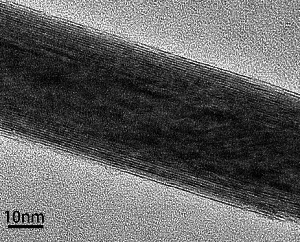
HRTEM image of WS2 nanotube.
2.2 Electrical wear apparatus and conditions
A block-on-slip ring type wear tester was used in this study and its corresponding schematic is shown in Figure 2A. Brushes were rubbing against Cu-5 wt% Ag alloy ring with a diameter of 320 mm, a width of 60 mm and a hardness of 105 HB. The slip ring was driven by a 294 kW variable-frequency electrical motor and the brush current was provided by a DC power supply which can provide a maximum current of 200 A. The normal load was provided by a constant-force spring to maintain contact between the brushes and slip ring. A flexible pure copper wire with 0.5 mm2 cross-sectional area was embedded in each brush at 5 mm from the sliding surface to measure the average contact voltage drop. The contact voltage drop was measured by the schematic presented in Figure 2B. The slip ring and brushes were both polished using 1200 mesh sand paper and cleaned with acetone before each test. The tests were performed under the ambient conditions at room temperature. The relative humidity and ambient temperature during the wear tests were 40%–60% and 15–20°C, respectively. Each test lasted for 5 h under a constant applied load of 2.5 N/cm2. The electrical current densities were set at 5 A/cm2, 7.5 A/cm2, 10 A/cm2, 12.5 A/cm2 and 15 A/cm2, respectively. The selected sliding velocities were 5 m/s, 7.5 m/s, 10 m/s, 12.5 m/s and 15 m/s, respectively. The wear losses of the brushes were determined by weighing them using a balance with 0.1 mg precision. Tribo-films formed on the worn surfaces of the brushes were analyzed by scanning electron microscopy and X-ray photoelectron spectroscopy (XPS).

Schematic for the wear test apparatus (A) and the measurement of contact voltage drop (B).
3 Results and discussion
3.1 Material characteristics of Cu-WS2-G-WSNTs
The microstructure of the sintered Cu-WS2-G-WSNTs is displayed in Figure 3A. Graphite shows thicker black strips while WS2 shows more scrappy strips, and both of them are dispersed uniformly in the gray copper matrix. No obvious cavities can be seen at the grain interfaces of the copper matrix and WS2 or graphite grains, indicating a dense microstructure of the composite. Energy dispersive X-ray spectroscopy (EDX) maps for carbon (Figure 3B) and sulfur (Figure 3C) corresponding to Figure 3A also reveal the morphologies and distributions of graphite and WS2 in the composite, which further confirm the view above.
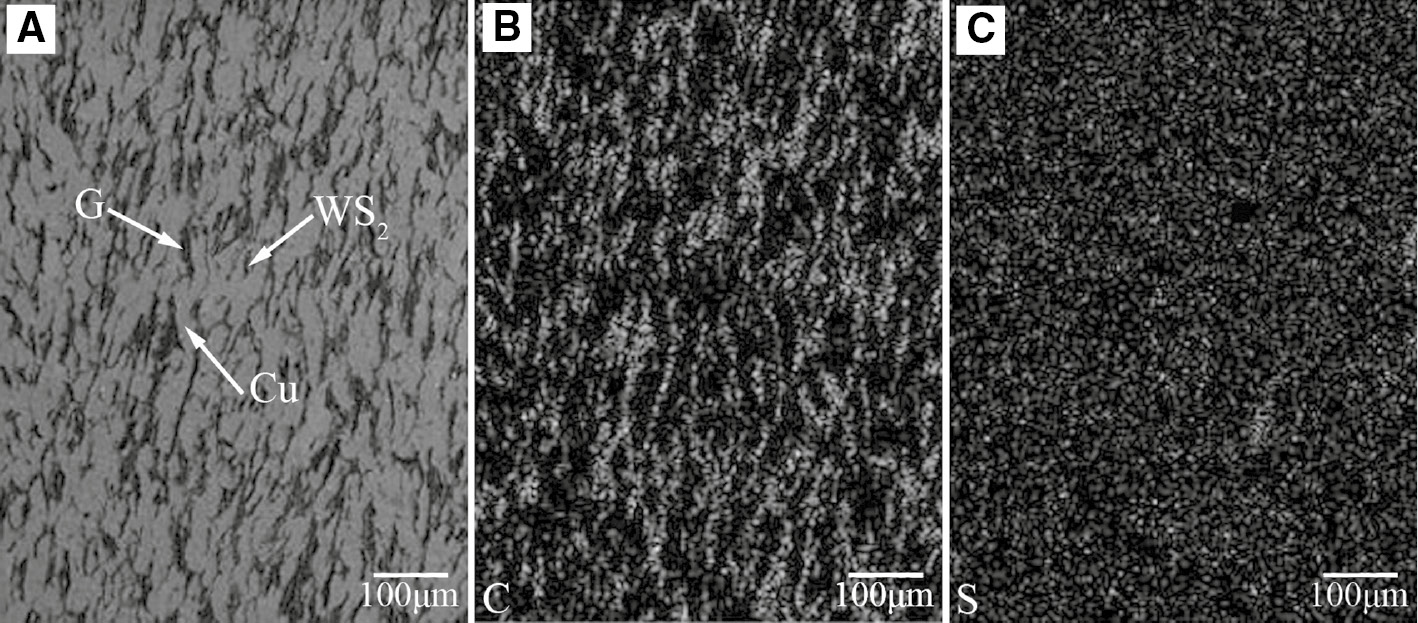
Microstructure (A) and corresponding EDX maps for carbon (B) and sulfur (C) of Cu-WS2-graphite-multi-wall WS2 nanotubes (Cu-WS2-G-WSNTs).
The fracture morphology shown in Figure 4 reveals that some WSNTs stretch out of the fracture surface, which are considered as reinforced additives to enhance the mechanical strength of the nanotube-additivated composite [20], [21], [22], [23]. The physical and mechanical properties of Cu-WS2-G-WSNTs and Cu-WS2-G are examined and listed in Table 1. It is noted that Cu-WS2-G-WSNTs have a more dense microstructure, better electrical conductivity and higher Brinell hardness than Cu-WS2-G.
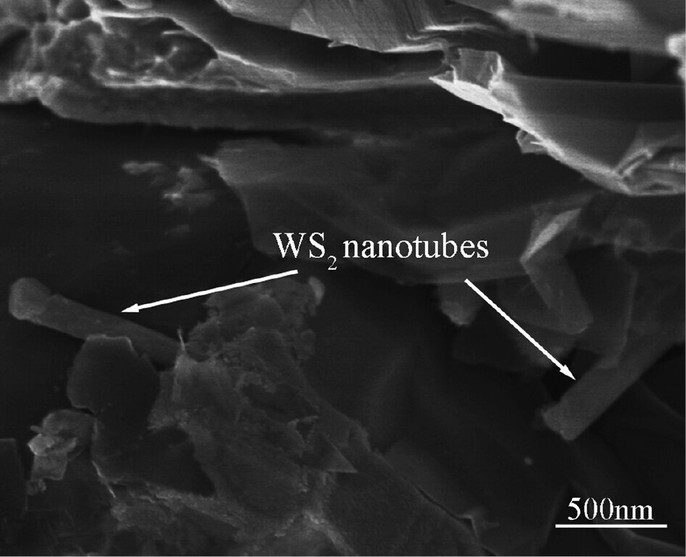
Scanning electron microscopy (SEM) image of fracture morphology of Cu-WS2-graphite-multi-wall WS2 nanotubes (Cu-WS2-G-WSNTs).
Physical and mechanical properties of Cu-WS2-graphite-multi-wall WS2 nanotubes (Cu-WS2-G-WSNTs) and Cu-WS2-G.
| Composites | Relative density (%) | Electrical resistivity (10−7 Ω·m) | Brinell hardness (HBS) |
|---|---|---|---|
| Cu-WS2-G-WSNTs | 93.72±0.31 | 2.59±0.03 | 34.68±0.70 |
| Cu-WS2-G | 92.55±0.25 | 2.84±0.04 | 30.78±0.65 |
3.2 Effects of electrical current and sliding velocity on the contact resistance
Contact resistance is one of the most important dynamic characteristics for electrical brush-rotor systems. Since the surface of a solid has a certain degree of roughness, the real contact area is only a small fraction of the apparent contact area [24]. When two conductive surfaces are brought into contact, electrical current lines constrict together to pass through narrow contact areas called “a-spots”. The electrical conduction area includes all the “a-spots” and is only a small part of the real contact area, which is significantly much smaller than the apparent contact area. As a result, the current density through the individual contact spots may exceed the statistical average value for several times. In the meantime, the tribo-films formed at the contact interfaces can hinder the flow of electrical current. According to the electrical contact theory [25], the contact resistance Rc is the sum of the tribo-film resistance Rf and constriction resistance Rs arising from the geometrical effect of current lines from specimen bulk to the contact spots, and it can be calculated by Eq. (1) as follows:
where U is the contact voltage drop and I is the electrical current.
Figure 5A presents the contact resistance of Cu-WS2-G-WSNTs as a function of electrical current with 2.5 N/cm2 of applied load and 10 m/s of sliding velocity. It can be seen that the contact resistance of the composite decreases as the electrical current increases. As is well known, when an electrical current is applied, heat such as frictional heat, Joule heat and arc heat would generate at the contact interface [26]. Because the arc is not observed during our experiments and the frictional heat is only a small proportion of the total heat, so the total heat mainly originated from the Joule heat. With the increase of electrical current, more Joule heat is generated and leads to the dramatic rise of interface temperature, which softens the materials at the “a-spots”, increasing the area of “a-spots” under the contact pressure and decreasing the constriction resistance. It can also be observed that with the increase of electrical current, the tribo-film on the composite worn surface after 5 h sliding (Figure 6) is gradually damaged and becomes discontinuous, which confirms the reduction of tribo-film resistance. For the above mentioned reasons, the contact resistance of the composite decreases as electrical current increases.
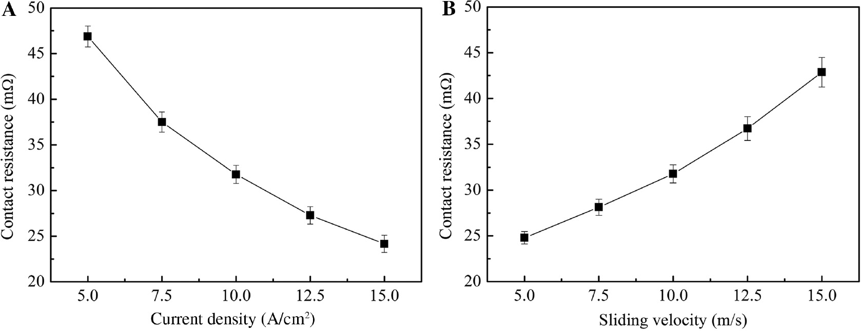
Contact resistance of Cu-WS2-graphite-multi-wall WS2 nanotubes (Cu-WS2-G-WSNTs) as a function of current density (A) and sliding velocity (B).
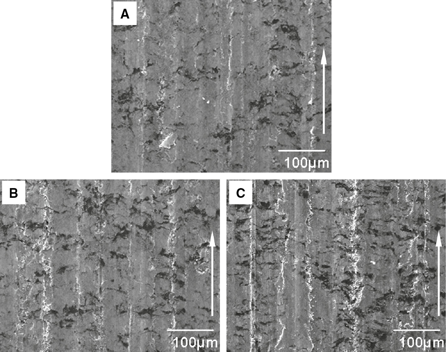
Scanning electron microscopy (SEM) micrographs of the worn surfaces of Cu-WS2-graphite-multi-wall WS2 nanotubes (Cu-WS2-G-WSNTs) under various current densities with 2.5 N/cm2 of applied load and 10 m/s of sliding velocity: (A) 5 A/cm2; (B) 10 A/cm2; (C) 15 A/cm2 (arrows show the sliding direction).
Figure 5B shows the relation between sliding velocity and contact resistance of Cu-WS2-G-WSNTs with 2.5 N/cm2 of applied load and 10 A/cm2 of electrical current. In contrast with the influence of electrical current, the contact resistance increases with the increase of sliding velocity, resulting from the adsorption of gaseous molecule film on the tangential direction of the slip ring surface, which acts as a fluid lubricant at the tribo-interface between the brush and slip ring. Continually increasing the sliding velocity results in increase of the gaseous pressure and thickness of the film; thus, the contact gap between the brush and slip ring expands, which further decreases the total electrical conduction area and induces an increment of the constriction resistance. Meanwhile, the thickened gaseous film also leads to a rise of the tribo-film resistance. As a result, the contact resistance of the composite increases as sliding velocity increases.
3.3 Effects of electrical current and sliding velocity on the wear rate
The wear of sliding electrical contact material under an electrical current is the result of electro-thermo-mechanical multi-field couple [5]. Figure 7A presents the variation of wear rate of Cu-WS2-G-WSNTs versus electrical current with 2.5 N/cm2 of applied load and 10 m/s of sliding velocity. A closely linear relationship is found between the wear rate and electrical current. Due to the adverse effects of electrical current, the high temperature at the tribo-interface softens the materials at the “a-spots” that facilitates the adhesion at contact regions. As a result, when some of the “a-spots” are punctured and finally detached from the base material under the contact pressure, the wear of composite increases. Furthermore, the rising interface temperature on the one hand hinders the cohesion process between the tribo-film and the base material and on the other hand, also favors the oxidation process of solid lubricants in the tribo-film, thereby reducing the lubricity of the tribo-film, so the tribo-film becomes flaky and discontinuous and could be easily removed (Figure 6), providing inadequate protection to the brush from damage by the slip ring. Bulk-shaped wear debris (Figure 8) also confirms that severe adhesive wear occurred when a higher electrical current applied to the composite. Therefore, the increased electrical current gives rise to the higher wear rate of the composite.
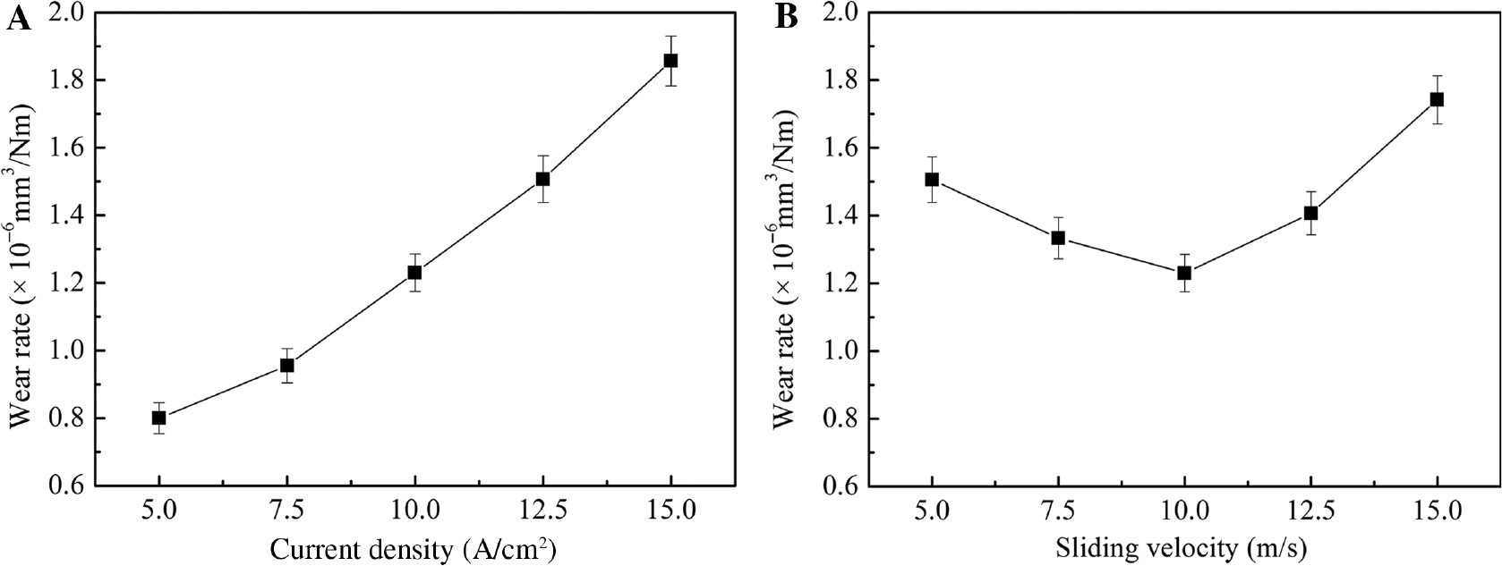
Wear rate of Cu-WS2-graphite-multi-wall WS2 nanotubes (Cu-WS2-G-WSNTs) versus current density (A) and sliding velocity (B).
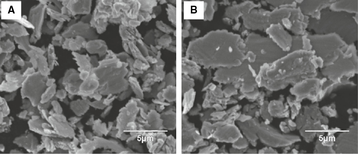
Scanning electron microscopy (SEM) micrographs of wear debris of Cu-WS2-graphite-multi-wall WS2 nanotubes (Cu-WS2-G-WSNTs) under various current densities with 2.5 N/cm2 of applied load and 10 m/s of sliding velocity: (A) 5 A/cm2; (B) 15 A/cm2.
Figure 7B shows the wear rate of Cu-WS2-G-WSNTs by varying the sliding velocity with 2.5 N/cm2 of applied load and 10 A/cm2 of electrical current. It is clear to see that the wear rate of the composite decreases slightly as the sliding velocity increases up to 10 m/s, and after that it increases dramatically. The wear rate gets to its minimum value at a sliding velocity of 10 m/s. The total wear of material with an applied electrical current consists of mechanical wear, electrical wear and spark wear [25]; in our case, the contact pressure is sufficient to inhibit the emergence of the arc, so the spark wear can be neglected. Based on the previous study [27], the mechanical wear of the brush material is proportional to the applied load according to Eq. (2):
where W is the wear rate, k is the wear coefficient, P is the applied load, x is the sliding distance and H is the hardness of the material. The gaseous film at the contact interface between the brush and slip ring could exert an upward force to the brush. With the rise of sliding velocity, the increasing gaseous pressure causes a higher upward force, which decreases the actual normal pressure applied to the brush and finally reduces the mechanical wear. Moreover, the high speed rotation of the slip ring enhances the fluid lubricity of the gaseous film. However, the increasing contact resistance leads to a rise of tribo-interface temperature and facilitates the electrical wear. Therefore, there could be an optimized sliding velocity that minimizes the total wear because the sliding velocity is a factor related to both frictional heat and Joule heat. At an ideal sliding velocity without much increase in Joule heat, the frictional heat and mechanical wear could be reduced, which lowers the total thermal effect and the resultant wear rate. In the present test, 10 m/s is the optimum sliding velocity under the selected experimental conditions. Figure 9 shows the scanning electron microscopy images of the worn surfaces of the composite after sliding for 5 h at different sliding velocities. It can be found that the composite has the most uniform and continuous tribo-film on the worn surface when sliding at a sliding velocity of 10 m/s, in good agreement with the relatively mild wear of the composite (Figure 7B).
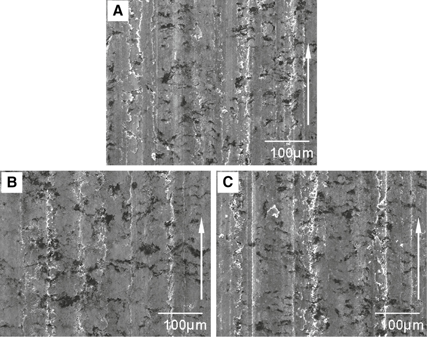
Scanning electron microscopy (SEM) micrographs of the worn surfaces of Cu-WS2-graphite-multi-wall WS2 nanotubes (Cu-WS2-G-WSNTs) at different sliding velocity with 2.5 N/cm2 of applied load and 10 A/cm2 of electrical current: (A) 5 m/s; (B) 10 m/s; (C) 15 m/s (arrows show the sliding direction).
3.4 Lubricating effect of WSNTs in Cu-WS2-G-WSNTs
In order to estimate the lubricating effect of WSNTs in Cu-WS2-G-WSNTs, the electrical wear properties of Cu-WS2-G-WSNTs and Cu-WS2-G were compared. The tests were performed with 10 A/cm2 electrical current under an applied load of 2.5 N/cm2 and at a sliding velocity of 10 m/s, and the corresponding results are listed in Table 2. Interestingly, the contact resistance and wear rate of Cu-WS2-G-WSNTs are both lower than those of Cu-WS2-G. WSNTs have super strong lubricity [19], high strength and a unique elastic modulus [20]; thus, the use of reasonable addition of WSNTs instead of WS2 powder in the Cu-WS2-G greatly improves both the mechanical strength and wear resistance. This explains the lower wear rate of Cu-WS2-G-WSNTs. WSNTs gradually fall off from the brush surface material and adhere to the frictional surface during electrical sliding friction, reducing the thickness of the tribo-film as a result of the grinding function of the nanotubes when they roll at the tribo-interface. For this reason, the nanotube-additivated composite shows a lower contact resistance.
Contact resistances and wear rates of Cu-WS2-graphite-multi-wall WS2 nanotubes (Cu-WS2-G-WSNTs) and Cu-WS2-G.
| Composites | Contact resistance (mΩ) | Wear rate (10−6 mm3/Nm) |
|---|---|---|
| Cu-WS2-G-WSNTs | 31.77±0.98 | 1.23±0.05 |
| Cu-WS2-G | 34.86±1.16 | 1.49±0.07 |
3.5 XPS analyses for the tribo-film of Cu-WS2-G-WSNTs
In the electrical wear process, the tribo-film formed at the interface converts the contact nature of the brush and slip ring from metal-metal to metal-film-metal and provides a lubrication action at the tribo-interface, thus reducing the friction and wear of the brush. Therefore, the tribo-films formed on the contact surfaces of sliding electrical contacts are the key to better understanding of the wear mechanisms. Figure 10 presents the XPS spectra for the tribo-film on the worn surface of Cu-WS2-G-WSNTs. From Figure 10A, it can be observed that the main existence form of C1s in the tribo-film is C-C (graphite). Other carbon bondings (-C-OH, C-O-C and -COOH/-C=O) in the tribo-film are ascribed to the oxidation products of graphite and carbon atoms in gas molecules absorbed from the atmosphere. Figure 10B and C confirm the oxidation of WS2/WSNTs into WO3 in terms of the following reactions:
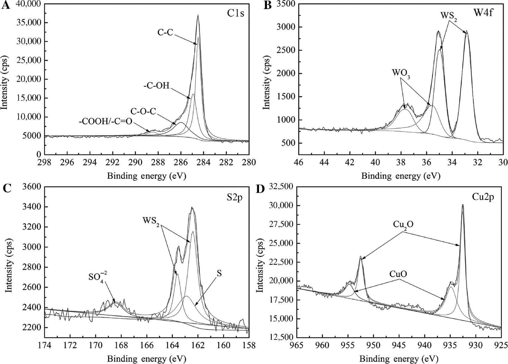
X-ray photoelectron spectroscopy (XPS) spectra for the tribo-film of Cu-WS2-graphite-multi-wall WS2 nanotubes (Cu-WS2-G-WSNTs) sliding under an applied load of 2.5 N/cm2 and at a sliding velocity of 10 m/s with 10 A/cm2 electrical current for 5 h.
The oxidation ratio of WS2/WSNTs in the tribo-film can be calculated to be about 36.27% under the investigated conditions (Figure 10B). Graphite can act as an oxygen diffusion barrier at the edge and as a water scavenger in worn areas to reduce WS2 oxidation when they are used combinedly, which improves the lubricity of WS2. An oxide layer consisting of copper oxides (CuO and Cu2O) is also formed on the contact surface due to the high tribo-interface temperature (Figure 10D). It has been proved that the copper oxides play an important role in reducing friction and wear in sliding electrical contacts [3]. The calculative volume ratio of copper oxides, graphite and WS2/WSNTs in this tribo-film is 2.11:8.84:1. Hence, it can be concluded from XPS analyses that copper oxides, graphite and WS2/WSNTs in the tribo-film play the main lubrication action at the tribo-interface during electrical wear process.
4 Conclusions
High-speed electrical sliding wear behaviors of Cu-WS2-G-WSNTs were investigated using a block-on-slip ring wear tester rubbing against Cu-5 wt% Ag alloy ring under 2.5 N/cm2 of applied load, and the following conclusions can be drawn from the test results:
The contact resistance decreases but the wear rate increases as electrical current increases from 5 A/cm2 to 15 A/cm2, because the adverse effects of electrical current soften the materials at “a-spots” and damage the tribo-film.
Due to the adsorption of a gaseous molecule film on the tangential direction of slip ring surface, with the rise of sliding velocity from 5 m/s to 15 m/s, the contact resistance increases while the wear rate reaches the minimum at the sliding velocity of 10 m/s.
The reasonable addition of WS2 nanotubes into the Cu-WS2-G to replace WS2 powder can reduce both contact resistance and wear rate.
Copper oxides, graphite, WS2, and WS2 nanotubes in the tribo-film play the main lubrication action at the tribo-interface during electrical wear process.
Funding source: National Natural Science Foundation of China
Award Identifier / Grant number: 91026018
Award Identifier / Grant number: 60979017
Award Identifier / Grant number: 51571078
Funding statement: This work was funded by the Major Research Program of the National Natural Science Foundation of China (Grant no. 91026018), the National Natural Science Foundation of China (Grant nos. 60979017, 51571078), the Fundamental Research Funds for the Central Universities (JZ2015HGBZ0473), and the science and technology planning project of Wenzhou city (Grant no. G20150023).
Acknowledgments
This work was funded by the Major Research Program of the National Natural Science Foundation of China (Grant no. 91026018), the National Natural Science Foundation of China (Grant nos. 60979017, 51571078), the Fundamental Research Funds for the Central Universities (JZ2015HGBZ0473), and the science and technology planning project of Wenzhou city (Grant no. G20150023).
References
[1] Shin WG, Lee SH. J. Mech. Sci. Technol. 2010, 24, 37–41.10.1007/s12206-009-1135-4Search in Google Scholar
[2] Qian G, Feng Y, Chen FY, Liu WH, Zhang XB, Liu YF. Sci. China. Technol. Sc. 2013, 56, 2839–2846.10.1007/s11431-013-5362-7Search in Google Scholar
[3] Hu ZL, Chen ZH, Xia JT. Wear 2008, 264, 11–17.10.1016/j.wear.2007.01.034Search in Google Scholar
[4] Feng Y, Zhang M, Xu Y. Carbon 2005, 43, 2685–2692.10.1016/j.carbon.2005.05.029Search in Google Scholar
[5] Wang YA, Li JX, Yan Y, Qiao LJ. Wear 2012, 289, 119–123.10.1016/j.wear.2012.04.006Search in Google Scholar
[6] Zhao H, Barber GC, LIU J. Wear 2001, 249, 409–414.10.1016/S0043-1648(01)00545-2Search in Google Scholar
[7] Uecker A. Wear 2003, 255, 1286–1290.10.1016/S0043-1648(03)00182-0Search in Google Scholar
[8] Argibay N, Bares JA, Sawyer WG. Wear 2010, 268, 455–463.10.1016/j.wear.2009.08.036Search in Google Scholar
[9] Lin JW, Chang HC. Tribol. T. 2011, 54, 887–894.10.1080/10402004.2011.613555Search in Google Scholar
[10] He DH, Manory R. Wear 2001, 249, 626–636.10.1016/S0043-1648(01)00700-1Search in Google Scholar
[11] Cho KH, Hong US, Lee KS, Jang H. Tribol. Lett. 2007, 27, 301–306.10.1007/s11249-007-9234-9Search in Google Scholar
[12] Yasar I, Canakci A, Arslan F. Tribol. Int. 2007, 40, 1381–1386.10.1016/j.triboint.2007.03.005Search in Google Scholar
[13] Xian GJ, Walter R, Haupert F. J. Appl. Polym. Sci. 2006, 102, 2391–2400.10.1002/app.24496Search in Google Scholar
[14] Wang QH, Zhang XR, Pei XQ. Mater. Design 2010, 31, 3761–3768.10.1016/j.matdes.2010.03.017Search in Google Scholar
[15] Gardos MN. Tribol. T. 1988, 31, 214–227.10.1080/10402008808981817Search in Google Scholar
[16] Shi C, Mao DH, Zhou M. B. Mater. Sci. 2010, 33, 529–534.10.1007/s12034-010-0081-1Search in Google Scholar
[17] Vadiraj A, Kamaraj M. J. Mater. Eng. Perform. 2010, 19, 166–170.10.1007/s11665-009-9432-8Search in Google Scholar
[18] Tenne R, Margulis L, Genut M, Hodes G. Nature 1992, 360, 444–446.10.1038/360444a0Search in Google Scholar
[19] Rapoport L, Fleischer N, Tenne R. J. Mater. Chem. 2005, 15, 1782–1788.10.1039/b417488gSearch in Google Scholar
[20] Ashiri IK, Tenne R. J. Clust. Sci. 2007, 18, 549–563.10.1007/s10876-007-0118-9Search in Google Scholar
[21] Zohar E, Baruch S, Shneider M, Dodiuk H, Kenig S, Tenne R, Wagner HD. J. Adhes. Sci. Technol. 2011, 25, 1603–1617.10.1163/016942410X524138Search in Google Scholar
[22] Lalwani G, Henslee AM, Farshid B, Parmar P, Lin LJ, Qin YX, Kasper FK, Mikos AG, Sitharaman B. Acta. Biomater. 2013, 9, 8365–8373.10.1016/j.actbio.2013.05.018Search in Google Scholar PubMed PubMed Central
[23] Naffakh M, Marco C, Ellis G, Cohen SR, Laikhtman A, Rapoport L, Zak A. Mater. Chem. Phys. 2014, 147, 273–284.10.1016/j.matchemphys.2014.04.040Search in Google Scholar
[24] Dow TA, Kannel JW. Wear 1982, 79, 93–105.10.1016/0043-1648(82)90206-XSearch in Google Scholar
[25] Slade PG. Electrical Contacts: Principles and Applications, Marcel Dekker Inc: New York, 1999.10.1201/9780585139319Search in Google Scholar
[26] Nagasawa H, Kato K. Wear 1998, 216, 179–183.10.1016/S0043-1648(97)00162-2Search in Google Scholar
[27] Wang YA, Li JX, Yan Y, Qiao LJ. Tribol. Int. 2012, 50, 26–34.10.1016/j.triboint.2011.12.022Search in Google Scholar
©2018 Walter de Gruyter GmbH, Berlin/Boston
This article is distributed under the terms of the Creative Commons Attribution Non-Commercial License, which permits unrestricted non-commercial use, distribution, and reproduction in any medium, provided the original work is properly cited.
Articles in the same Issue
- Frontmatter
- Review
- A review on the intensification of metal matrix composites and its nonconventional machining
- Original articles
- Optimization of multi-sandwich-panel composite structures for minimum weight with strength and buckling considerations
- An automated portable multiaxial pressure test rig for qualifications of glass/epoxy composite pipes
- Effects of nano-SiO2 on mechanical and hygric behaviors of glass fiber reinforced epoxy composites
- Comparison of the mechanical and wear behaviour of aluminium alloy with homogeneous and functionally graded silicon nitride composites
- Engineering behavior of clay soils stabilized with class C and class F fly ashes
- Preparation and erosion-corrosion behavior of polyetheretherketone (PEEK)/nickel foam co-continuous composites
- Optimization design, manufacturing and mechanical performance of box girder made by carbon fiber-reinforced epoxy composites
- Recent advances in the manufacturing processes of functionally graded materials: a review
- Numerical prediction of thermal conductivity in ZrB2-particulate-reinforced epoxy composites based on finite element models
- High-speed electrical sliding wear behaviors of Cu-WS2-graphite-WS2 nanotubes composite
- Adsorption removal of methylene blue from aqueous solution on carbon-coated Fe3O4 microspheres functionalized with chloroacetic acid
- Thermal degradation of coir fiber reinforced low-density polyethylene composites
- Preparation and analysis of polypropylene composites with maleated tea dust particles
- Predicting the thermal conductivity of polypropylene-multiwall carbon nanotubes using the Krenchel model
- Growth mechanism of 3D graphene-carbon nanotube hybrid structure
- Reinforcing abilities of microfibers and nanofibrillated cellulose in poly(lactic acid) composites
- Sintered TiO2/recycled glass composites designed for the potential degradation of waterborne pollutants
- Evaluation of glass-fiber grafted by epoxide-terminated hyperbranched polymer on the effect of mechanical characterization of epoxy composites

