The effect of the percentage of steered plies on the bending-induced buckling performance of a variable stiffness composite cylinder
-
Mohammad Rouhi
 ,
Hossein Ghayoor
,
Hossein Ghayoor

Abstract
The fiber steering capability of automated fiber placement machines offers the designers more room to fully exploit the directional properties of composite materials. Circumferential stiffness tailoring by fiber steering can considerably increase the bending-induced buckling performance of laminated composite cylinders. The potential structural improvement resulting from fiber steering depends on different design parameters such as the number of plies considered for fiber steering in a laminate. In this study, the buckling performance improvement of a variable stiffness (VS) composite cylinder is investigated for different percentages of plies considered for fiber steering in a multilayered composite laminate. A surrogate-based modeling along with a multi-step optimization is used in the design procedure of this study. The improvements in the buckling performance are shown and verified using finite element analysis in ABAQUS software. The mechanisms leading to buckling performance improvement of VS composites are also investigated and presented for different percentages of fiber-steered plies.
1 Introduction
Variable stiffness (VS) composite structures have been shown to be very promising in terms of the structural performance improvements they can offer compared with their constant stiffness (CS) counterparts [1–5]. Unlike CS, in VS composite laminates the fiber orientation angle can continuously vary by steering the fibers/tows in the fiber/tow placement process. The spatial variation of the fiber orientation angle in VS composites has been accommodated by using the fiber steering capability of the automated fiber placement (AFP) machines. A designer can take advantage of the fiber steering to extend the design space and make the full exploitation of the directional properties of composite materials to design VS structural components with considerably higher performance compared with their CS counterparts. However, there are several challenges that need to be addressed to find the full potential of VS composite structures made by fiber steering.
Sun and Hyer [2] showed that the axial buckling of an elliptical composite cylinder can considerably be improved by stiffness tailoring via fiber steering. White and Weaver [6] studied the potential for achieving bend-free states in shell structures subjected to internal pressure, via stiffness tailoring provided by fiber steering. Their results showed that non-circular cylindrical shells are hardly compatible with a completely bend-free design. However, shells with extremely thick asymmetric laminates can be used to tailor completely bend-free states by fiber steering.
Khani et al. [5] could improve the buckling loads for cylindrical composite shells by 15–30% using fiber steering with consideration of manufacturing constraints. Blom et al. [3] tailored the circumferential stiffness of a composite cylinder to improve its bending-induced buckling load. They reported up to 17% improvement in the buckling load by softening the compression side and stiffening the tension side as a result of the fiber steering over the circumference of the cylinder. Rouhi et al. [7] also used a surrogate-based modeling and multi-step design optimization technique in the buckling design of VS composite cylinders. They investigated the effects of the geometrical parameters of the cylinder on the improvement in the structural performance. Their results showed that there is more room for buckling improvement for shorter cylinders having a lower aspect ratio (L/R≤2). This improvement could potentially become >38% for very short cylinders (L/R=0.1). Rouhi et al. [8] also used their multi-step design optimization technique for multiobjective design optimization of VS composite cylinders in which multiple loads are applied on the structure. Their results showed that reducing the inhomogeneity of the loading will result in a reduced structural improvement of a VS composite cylinder.
Spatial variation of the fiber orientation angle in each ply of a laminated composite structure gives the designer more room to explore the extended design space for finding the optimum design. This is, however, at the expense of the increased number of design variables, making the design optimization problem more complicated and computationally expensive. In the design optimization process of a VS composite structure, usually a limited number of plies [3] or all of the plies in the laminate [5] are considered as candidates for fiber steering. To the knowledge of the authors, the effect of the number of candidate plies for fiber steering on the potential structural performance of a VS composite structure has not been studied.
In this paper, the number of plies candidate for fiber steering (number of design variables) is increased step by step, and its effect on the potential improvement in bending-induced buckling performance of a laminated composite cylinder is investigated. To this end, a balanced symmetric quasi-isotropic (QI) laminate with [+45/0/-45/90/-45/0/+45/90] stacking sequence is considered. Keeping the balance-symmetry of the laminate, in the first step only ±45°-plies are considered for fiber steering. In the next step, 90°-plies are added to the design space by considering them for fiber steering. Finally, 0°-plies are also included in the candidate plies for fiber steering so that the design domain cover all of the plies in the stacking sequence. In each step, the structural performance (buckling load) improvement compared with the QI baseline laminate is calculated.
2 Modeling and analysis
Figure 1 shows a composite cylinder subjected to a pure bending load. The length and diameter of the cylinder considered in this study are 18 in. A 16-ply balanced symmetric QI laminate ([+45/0/-45/90/-45/0/+45/90]s) is considered as a baseline to compare with its VS counterparts in the structural performance (buckling load). The mechanical properties of the material system considered in the composite laminate (AS4D/9310 carbon/epoxy) are given in Table 1.

The composite cylinder with QI stacking sequence subjected to bending-induced buckling.
Material properties of the carbon/epoxy composite plies.
| Property | AS4D/9310 |
|---|---|
| EL (GPa) | 134 |
| ET (GPa) | 7.71 |
| GLT (GPa) | 4.31 |
| GT (GPa) | 2.76 |
| vLT | 0.301 |
| vT | 0.396 |
| Vf | 0.55 |
| Thickness (mm) | 0.127 |
The commercial software ABAQUS was used for finite element (FE) analysis of the cylinder to calculate the buckling load. Followed by a mesh convergence study, the cylinder was discretized into 98 segments on the circumference and 30 segments on the length. The S8R5 shell elements of ABAQUS were used in this study that have eight nodes and 5 degrees of freedom in each node [9].
For VS laminates, some of the plies are considered to have variable fiber orientation angles. Figure 2A illustrates this variation of the orientation angle in fiber-steered plies. To approximate the continuous variation of the fiber angles, a piece-wise constant model is used. In this model, the surface of the cylinder is divided into a limited number of subsections (Figure 2B) in which the fiber orientation angle is considered constant. In this study, the cylinder is divided into 98 subsections as shown in Figure 2B. It is worth noting that due to the symmetric loading and boundary conditions, the orientation angles for VS subsections will also be symmetric:

(A) Fiber path in a VS ply and (B) piece-wise constant model for approximating the varying orientation angles of fibers in VS layers.
It is worth noting that, in this study, it is assumed that the stacking sequence is previously designed (based on stacking sequence considerations). In other words, the stacking sequence is assumed to be prearranged and the orientation angle variation of those plies candidate for fiber steering is to be optimized. Therefore, the optimized design is not claimed to fully cover the entire design space (including the stacking sequence optimization). One theoretical approach to fully explore the design space is using the lamination parameters [10, 11]; however, a difficulty with using this method is the incorporation of strength constraints in the design optimization procedure [12]. In addition, the imperfection sensitivity is not studied in this work. Previous studies [11, 13] also show that the VS laminates do not appear to be highly sensitive to imperfections. However, additional research is needed to quantitatively study the effect of imperfection on the structural performance of both CS and VS designs.
3 Design optimization
The design optimization of VS composite cylinder for buckling in this study is to find the optimum fiber path for fiber-steered plies to maximize the buckling load. To this end, for each fiber-steered ply, the orientation angles for 49 subsections need to be calculated. To reduce the number of design variables, the variable orientation angle in each fiber-steered ply is assumed to vary in four steps from keel to the crown of the cylinder. Regarding the symmetry of the loading and boundary conditions, there will be five design variables per VS ply, T1, …, T5, as shown in Figure 2B. The orientation angle is assumed to vary linearly from one design variable (Ti) to the next one (Ti+1):
where i and k are index numbers for the design variables and the subdivisions in between two adjacent design variables, respectively. This way, the number of design variables are reduced from 49 to 5 for each fiber-steered ply. To maintain the balance-symmetry of the whole laminate, ±θ-plies are steered synchronously, resulting in five design variables for each 4-ply group having ±θ orientation angles. Table 2 shows the different VS laminates considered in this study for design optimization.
VS laminates with different number of plies considered for fiber steering.
| Case | Stacking sequence | Steered plies/total plies | Number of design variables |
|---|---|---|---|
| 1 | [45/0/-45/90/-45/0/45/-90]s | [0/16] | – |
| 2 | [θ1/0/-θ1/90/-45/0/45/-90]s | [4/16] | 5 |
| 3 | [45/0/-45/90/-θ1/0/θ1/-90]s | [4/16] | 5 |
| 4 | [θ1/0/-θ1/90/-θ2/0/θ2/-90]s | [8/16] | 10 |
| 5 | [θ1/0/-θ2/90/-θ1/0/θ2/-90]s | [8/16] | 10 |
| 6 | [θ1/θ2/-θ1/90/-θ3/-θ2/θ3/-90]s | [12/16] | 15 |
| 7 | [θ1/0/-θ1/θ2/-θ3/0/θ3/-θ2]s | [12/16] | 15 |
| 8 | [θ1/θ2/-θ1/θ3/-θ4/-θ2/θ4/-θ3]s | [16/16] | 20 |
Owing to several iterations needed in the design optimization process, it usually requires a large number of function evaluations. In this case, FE analysis (FEA) was used as the high-fidelity model for function evaluations (buckling load). Regarding the fact that FEA is a computationally expensive step, a major challenge is to find a way to reduce the computational cost of the optimization procedure. Surrogate models or the so-called metamodels are approximate analytical functions that are used to alleviate the problems associated with the computational cost. Another advantage of metamodeling techniques is that they can change the noisy responses into a smooth one, resulting in a more appropriate function to be optimized by gradient-based optimization methods. There are several metamodeling techniques that have successfully been used in structural design optimization [14–17], especially for VS composite structures [18, 19]. For design optimization of VS composite structures, radial basis functions (RBFs) have been shown to offer accurate and robust response approximations at a relatively high computational efficiency [18, 19]. Therefore, in this study, RBF is used as the metamodeling technique to approximate the buckling load (i.e., Mcr) in terms of the design variables (i.e., Ti’s). Four formulations of RBF – thin plate spline, Gaussian, multiquadric, and inverse multiquadric [7, 18] – are examined in this study and the best approximation was used in the optimization process.
Metamodeling here includes calculating the buckling load of the VS composite cylinder in a limited number of training points (sample points) using the high-fidelity FEA and fit the RBF so that it passes through all these points. The sample points or the design of experiment were generated using the Latin hypercube sampling method to create a populated design space where points are well distributed throughout the design domain. The number of sample points is an important factor that affects the accuracy and robustness of the metamodel. It is worth noting that by increasing the number of design variables, more sample points are required to build a metamodel with acceptable degree of accuracy and robustness. To evaluate the error associated with each metamodel, a number of test points (=0.1 of the number of samples) were also generated for which the objective function (buckling load) is evaluated using both metamodel approximated function and high-fidelity FEA. The average error was calculated as a representation of the metamodel’s error.
To reduce the error associated with the metamodeling technique compared with the high-fidelity FEA, a multi-step design optimization technique was used [7, 18]. In the multi-step optimization procedure, the design domain is tightened around the optimum points found in the previous design optimization step, and the metamodeling and optimization procedure is repeated for the new design domain until a convergence is reached as shown in Figure 3. To generate the corresponding FE model for each sample/test point, including the mesh size, stacking sequence, material properties, and orientation angle distribution (Ti’s), a Python script was written in this study. The script also runs ABAQUS to compute the buckling response (Mcr) for each sample/test point. The values of the buckling loads along with their corresponding sample points are collected in a text file used as an input to the metamodel generating code written in MATLAB. The output from the MATLAB code is the metamodel that is used as an analytical surrogate model defining the response (Mcr) in terms of the design variables (Ti’s). For the optimization part in each step, genetic algorithm (GA) is used in this study. As the computationally inexpensive analytical functions (surrogate models) are the ones called in the optimization procedure, using GA with a large population was reasonable because of its accuracy and robustness in finding the global optimum.

Multi-step design optimization procedure.
4 Results
For the composite cylinder with [+45/0/-45/90/-45/0/+45/90]s stacking sequence (baseline laminate), the buckling analysis was performed using FEA in ABAQUS, as stated in Section 2. The FEA resulted in the buckling mode shown in Figure 4A, and the critical buckling load (Mcr=9.53e4 Nm) was calculated. As expected, a small area at the upper part of the cylinder (crown) is involved in carrying the compressive load. This area is expected to increase by stiffness tailoring (fiber steering), resulting in a better distribution of compressive load and consequently an improved buckling performance. Figure 4B reveals the increase in this area for case 2 laminate (i.e., [θ1/0/-θ1/90/-45/0/45/90]s). The optimum orientation angle distribution of the steered plies is shown in Figure 5A that causes the maximum compressive load to drop and be transferred to the tensile side, as shown in Figure 5B. The better load transfer along with the increased area involved in carrying the compressive load are the main outcomes of stiffness tailoring that improve the buckling performance of the VS composite cylinder. For this case (case 2 in Table 2), in which 25% of the laminate was steered, the results showed about 14.5% improvement in the buckling load compared with the one for QI laminate. Case 3 in Table 2 is another alternative for steering 25% of the laminate for which the results showed an improvement in the buckling load (14.7%) not considerably different from case 2.
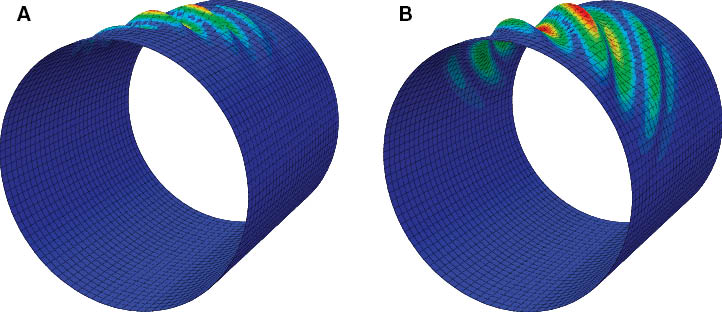
The buckling mode of the composite cylinder with (A) QI and (B) VS laminate with 25% of layers considered for fiber steering (case 2).

(A) Optimum orientation angle distribution of steered plies and their counterparts in QI laminate and (B) resultant normal section force in QI and VS cylinder (case 2).
The orientation angle distributions for all cases listed in Table 2 resulting from the design optimization process are shown in Figure 6. The design optimization reveals a general tendency for the orientation angles of the steered plies to get closer to 0° in the lower part (tensile side), but higher degrees (45° to 90°) in the upper part (compression side) of the cylinder. This way, the compressive load is distributed more effectively in the compression side and transferred to the tension side of the cylinder, resulting in a higher buckling performance compared with the one with the QI laminate. The buckling load of VS composite cylinders for different stacking sequence cases are shown in Figure 7. Comparing the results of case 2 with case 3 and case 4 with case 5, it can be concluded that switching the synchronicity of the steering layers does not considerably affect the improvement of the buckling load. However, from the results for case 6 and case 7, one can conclude that for the QI laminate the 0°-plies are better candidates for steering compared with 90°-plies. In other words, in the case of bending-induced buckling of this composite cylinder, reducing the stiffness at the upper part (compression side) that results in a better compressive load distribution is relatively more important than increasing the stiffness at the lower part (tensile side) to carry the tensile load.
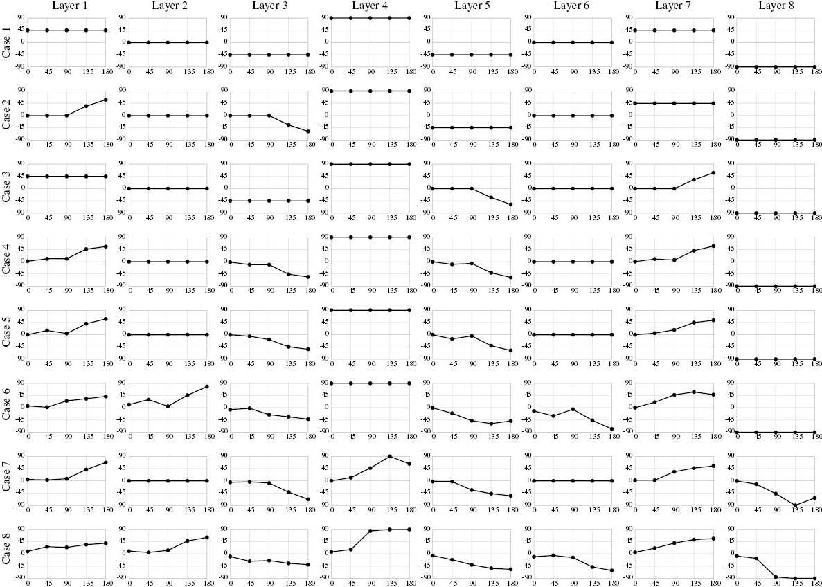
Orientation angle distribution of all layers for different stacking sequence cases listed in Table 2.

Buckling load of VS composite cylinders with different stacking sequence cases listed in Table 2.
The maximum potential improvement in the buckling performance of VS composite cylinders compared with the QI laminate is shown in Figure 8 for different percentages of the steered layers. As expected, increasing the percentage of the steered layers results in a higher improvement in the buckling performance. The normal resultant force distribution on the circumference of the VS composite cylinder with 100% layers involved in fiber steering (case 8) is shown in Figure 9. Comparing this figure with Figure 5B, one can observe the highly increased area for carrying the compressive load and maximum load transfer to the tension side of the cylinder in case 8 in which 100% layers are involved in fiber steering. The maximum increase of the area involved in carrying the compressive load is also observable in Figure 10 in which the buckling mode of QI laminate and case 8 are shown (compare it with Figure 4).
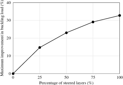
Maximum buckling load improvement of VS over QI laminate in terms of the percentage of the number of plies considered for fiber steering.
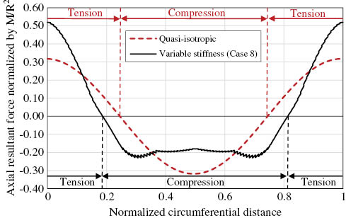
Resultant normal section force in QI and VS cylinder (case 8).
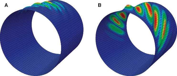
The buckling mode of the composite cylinder with (A) QI and (B) VS laminate with 100% of layers considered for fiber steering (case 8).
5 Conclusions and future work
A 16-ply VS composite cylinder made by fiber steering was optimized for maximum buckling performance due to pure bending load. The design optimization was performed using RBF-based surrogate modeling and GA. A multi-step design optimization technique was also used to reduce the error associated with metamodeling. The design optimization results showed a general tendency for the orientation angles of the steered plies to get closer to 0° in the tensile side, but higher degrees (45°–90°) in the compression side of the cylinder. As a result, the compressive load is distributed more effectively in the compression side and transferred to the tension side of the cylinder that gives higher buckling performance compared with the one with QI laminate.
The number of plies candidate for fiber steering was also increased from 0% (constant stiffness quasiisotropic laminate) to 100% (completely VS laminate) to study its effect on the buckling performance. The buckling improvement compared with the QI laminate was presented for VS laminates with different percentages of steered plies. The buckling improvement was shown to increase with the increase of the number of layers considered for fiber steering. For the composite cylinder considered in this study, a VS composite laminate with 100% of plies considered for fiber steering resulted in about 33% improvement in the buckling load.
It is worth noting that the improvements reported in this work are without considering the manufacturing constraints such as gap/overlap due to fiber/tow steering. Other structural constraints such as failure were also not addressed in this work. These constraints, along with studying cylinders with non-circular cross sections, are the subjects we plan to address in our future work.
Acknowledgments
The financial contributions from the Natural Sciences and Engineering Research Council of Canada industrial chair on Automated Composites, Bell Helicopter Textron Canada Ltd., Bombardier Aerospace, Delastek Ltd., and Concordia University are appreciated.
References
[1] Hyer MW, Charette RF. AIAA J. 1991, 29, 1011–1015.Suche in Google Scholar
[2] Sun M, Hyer MW. AIAA J. 2008, 46, 770–782.Suche in Google Scholar
[3] Blom AW, Stickler PB, Gürdal Z. Compos. Part B: Eng. 2010, 41, 157–165.Suche in Google Scholar
[4] Alhajahmad A, Abdalla MM, Gürdal Z. J. Aircraft 2010, 47, 775–782.10.2514/1.40357Suche in Google Scholar
[5] Khani A, Abdalla MM, Gürdal Z. Compos. Struct. 2012, 94, 2851–2860.Suche in Google Scholar
[6] White S, Weaver PM. Compos. Struct. 2012, 94, 3207–3214.Suche in Google Scholar
[7] Rouhi M, Ghayoor H, Hoa SV, Hojjati M. Compos. Struct. 2014, 118, 472–481.Suche in Google Scholar
[8] Rouhi M, Ghayoor H, Hoa SV, Hojjati M. Compos. Part B: Eng. 2015, 69, 249–255.Suche in Google Scholar
[9] ABAQUS Inc. ABAQUS Version 6.11 User’s Manual. ABAQUS Inc.: Pawtucket, RI, USA, 2011.Suche in Google Scholar
[10] Setoodeh S, Abdalla MM, Gürdal Z. Compos. Part B: Eng. 2006, 37, 301–309.Suche in Google Scholar
[11] Wu KC, Stanford BK, Hrinda GA, Wang Z, Martin RA, Kim HA. In Collection of Technical Papers, AIAA/ASME/ASCE/AHS/ASC Structures, Structural Dynamics and Materials Conference, Boston, MA, USA, April 2013.Suche in Google Scholar
[12] Blom AW. Structural performance of fiber-placed variable-stiffness composite conical and cylindrical shells. PhD thesis, Delft University of Technology, 2010.Suche in Google Scholar
[13] White SC, Raju G, Weaver PM. J. Mech. Phys. Solids 2014, 71, 132–155.10.1016/j.jmps.2014.07.003Suche in Google Scholar
[14] Queipo NV, Haftka RT, Shyy W, Goel T, Vaidyanathan R, Tucker KP. Prog. Aerosp. Sci. 2005, 41, 1–28.Suche in Google Scholar
[15] Wang GG, Shan S. J. Mech. Design, Transact. ASME 2007, 129, 370–380.10.1115/1.2429697Suche in Google Scholar
[16] Rouhi M, Rais-Rohani M. Compos. Struct. 2013, 95, 346–353.Suche in Google Scholar
[17] Rouhi M, Rais-Rohani M, Najafi A. Compos. Struct. 2013, 100, 144–153.Suche in Google Scholar
[18] Rouhi M, Ghayoor H, Hoa SV, Hojjati M. In Proceedings of ASC 29th Technical Conference, 16th US-Japan Conference on Composite Materials, ASTM-D30 Meeting, La Jolla, CA, USA, September 2014.Suche in Google Scholar
[19] Nik MA, Fayazbakhsh K, Pasini D, Lessard L. Compos. Struct. 2014, 107, 494–501.Suche in Google Scholar
©2015 by De Gruyter
This article is distributed under the terms of the Creative Commons Attribution Non-Commercial License, which permits unrestricted non-commercial use, distribution, and reproduction in any medium, provided the original work is properly cited.
Artikel in diesem Heft
- Frontmatter
- Editorial
- Automated composites manufacturing
- Review
- Modelling the effect of gaps and overlaps in automated fibre placement (AFP)-manufactured laminates
- Original articles
- Simulation and experimental validation of gaps and bridging in the automated fiber placement process
- The effect of the percentage of steered plies on the bending-induced buckling performance of a variable stiffness composite cylinder
- Size-dependent behavior of laminates with curvilinear fibers made by automated fiber placement
- Impact of layup rate on the quality of fiber steering/cut-restart in automated fiber placement processes
- Effect of autoclave process on the quality of thermoplastic composite truncated cones manufactured using automated fiber placement technique
- Design and automated manufacturing of profiled composite driveshafts
- Novel form-flexible handling and joining tool for automated preforming