Investigation of optimum cutting parameters and tool radius in turning glass-fiber-reinforced composite material

Abstract
Glass-fiber-reinforced composite materials (GFRPs) are used widely in various fields of engineering. Turning is the principal process conducted on these materials for obtaining minimum surface roughness. Machining of GFRP materials is different from traditional style due to their inhomogeneous and anisotropic structures. Optimum machining parameters for specific GFRP materials need to be ascertained for perfect machining. In this study, the influence of cutting parameters and insert radius on the cutting force and surface roughness of GFRP material during machining was investigated. For measuring main cutting force, a three-component piezoelectric crystal type of dynamometer was used. Cutting force and surface roughness were experimentally measured through longitudinal axes of the GFRP material. Through this study, it was observed that high cutting speeds and low feed rates provide the best surface quality in the turning process of GFRP composite materials.
1 Introduction
Advanced technology is required to have materials with extraordinary properties that cannot be met by traditional metal alloys, ceramics, and polymer materials. High-tech materials with extraordinary properties are developed by combining two or more materials complying with different characteristics in macrostructure with specific ratios under some certain physical conditions [1].
The most important and widely used composite materials are reinforced fibers. The design objective of fiber-reinforced composites is generally concentrated on producing materials with high strength and/or high stiffness as well as low weights. Of all fiber-reinforced polymer composites, glass-fiber-reinforced polymer (GFRP) composites are the most popular ones because of retaining advantages such as high strength, easily attainable, economic, and good corrosion resistance [1, 2]. Owing to these superior properties, GFRP composites are used in a wide spectrum from airplanes to variety of machine tools, as alternative to conventional materials [2–4].
The first theoretical research in this field was carried out by Everstine and Rogers in 1971. It analyzed plane deformation of incompressible reinforced composites structured with strong parallel fibers [5, 6]. Since then, the research in this field has continuously developed and expanded in both synthesis and analysis perspectives. Composites that have inhomogeneous and anisotropic [7, 8] structures are subject to machining (turning, milling, and drilling), as a secondary process, to achieve surface quality and dimensional accuracy [3, 9, 10]. Turning is the primary machining operation considered in most industrial production processes [11]. In the turning process, some problems on the subject of cutting tool and work-piece such as tool wear and surface roughness are encountered. Surface roughness affects the properties of wear resistance, fatigue behavior, friction coefficient, lubricating, wear rate, and resistance against corrosion of machined parts [11, 12]. Since GFRP composites are extremely abrasive, proper selection of the cutting tool and cutting parameters is needed for a perfect machining process [13]. In this direction, a variety of studies have been conducted on analyzing the effects of cutting parameters, insert radius, as well as derivatives of these parameters on the surface roughness of different composite materials with various cutting tools [6, 13, 14], cutting speeds [6, 7, 10, 15–19], feed rates [6, 7, 10, 15–17], and fiber orientation [6, 7]. Also, a variety of analyzing strategies such as optimizing cutting parameters using multiple analysis regression [16], hand lay-up making use of orthogonal array, and analysis of variance statistical technique [16] have been developed. In these studies, it has been reported that surface roughness increased in response to increasing feed rate and decreasing tool radius [7, 10, 15] and cutting velocity [15–19]. Also, it has been suggested that for obtaining a better machinability index, polycrystalline diamond tools were better than cemented carbide cutting tools [14].
Khan and Kumar [13] investigated surface roughness and tool wear as a consequence of processing GFRP composite material with filament winding produced in their laboratory using silicon carbide (SiC) whisker reinforced alumina cutting tool (CC670) and titanium carbon nitride (Ti[C, N]) mixed alumina cutting tool. They found that surface roughness obtained by the SiC whisker reinforced alumina cutting tool was better than the one obtained by the Ti[C, N] mixed alumina cutting tool. Recently, using polycrystalline diamond (PCD) tool turning polytetrafluroethylen composites, Fetecau and Stan [15] analyzed the effect of cutting parameters and insert radius on cutting force and surface roughness. They discovered that surface roughness was considerably affected by feed rate and insert radius such that the surface roughness increased with a rise in feed rate and decreased with a rise in insert radius. They showed that cutting speed and depth of cut had a small effect on surface roughness, and surface roughness decreased very little with an increase in depth of cut and cutting speed. Experiments [9, 20] conducted on machining of GFRP by means of tool materials Cubic boron nitride (CBN), PCD, and single crystal diamond), geometries (round and straight), and fiber orientation (angles varying from 300° to 900°) suggested that a low cutting force and single crystal diamond tool are effective in producing good quality surface and that a straight-edge tool is better than a round-edge tool. The experiments revealed that, while a decrease in feed rate improved surface quality, the depth of the cut and cutting speed did not affect the surface finish. They also showed that cutting force and surface roughness are highly influenced by feed, followed by cutting speed and angle of fiber orientation, while depth of cut less effected surface roughness [20]. Davim et al. [21] performed a study to minimize the surface delaminating problems arising from material and cutting parameters in milling composite materials. They evaluated the cutting parameters based on delaminate factors, surface roughness, international dimensional precision, and cutting parameters in two different GFRP composite materials. They showed that feed rate was the most prominent parameter affecting cutting force and that surface roughness increased with feed rate and decreased with cutting speed, which was also confirmed by other authors [6, 7, 10, 16]. Kalla et al. [8] developed a methodology for estimating cutting forces in carbon-fiber-reinforced polymers by using helical end mill in various fiber orientations. Darlewski and Gunthe [22] studied turning of glass-fiber-reinforced (GFR) epoxy and phenol and found that surface roughness increased with the increase in feed rate but did not change with the cutting speed.
From a theoretical point of view, model-based studies have also been introduced in the literature. For estimating tool wear [23] and surface roughness [17] in machining of GFRP composites, mathematical models in which regression and variance analysis and response surface method have been used have been developed. A variety of practical and theoretical works not mentioned here are dedicated for determining optimum processing parameters, because extreme cutting forces create damages in material. Material that has damages cannot be accepted within the production cycle; there should be minimum processing damage to reduce the production cost. Yet, a standard scheme on the processing parameters of GFRP composites has not been established because variations in the material’s structure have an effect on the analysis results. To go further beyond ambiguity in this issue, additional studies are needed.
The objective of this study was to investigate the effect of cutting parameters on surface roughness of GFRP composites using cutting tools having different nose radius. As a result of this particular systematic process carried out on the GFRP material, it was found that the combination of low feed rate, high cutting speed, and tool radius is essential in minimizing surface roughness during turning of GFRP composite materials.
2 Materials and methods
In this experimental study, GFRP composite pipes were chosen as test materials according to international standards, G10-FW/HGW 2375. The GFRP pipes were filament-wound tubes made up from continuous E glass filaments structured in the form of roving and saturating with epoxy resin, which is recommended for applications requiring high mechanical strength and good electrical resistance. The technical specifications of the GFR material used in this work are given in Table 1.
Typical properties of filament-wound tubes.
| Property | Test method | Unit | G10-FW/HGW 2375 |
|---|---|---|---|
| Mechanical properties | |||
| Tensile strength | ISO 527 | MPa | 300 |
| E Modules | ISO 178 | GPa | 20 |
| Flexural strength | ISO 178 | MPa | 350 |
| Physical properties | |||
| Specific gravity | ISO 1183-A | g/cm3 | 1.8 |
| Water absorption | ISO 62/1 | Mg/cm2 | 0.3 |
| Temperature index | IEC 216 | T.I | 130°C |
| Electrical properties | |||
| Electrical strength in oil at 90°C | IEC 243-1 | Kv/mm | 11 |
| Dissipation factor 50 Hz | IEC 250 | 4.5 | |
| Permittivity 50 Hz | IEC 250 | 0.01 | |
The experiments were carried out in pipes with walls of 50 mm diameter and 6 mm thickness. The material was turned on a lathe SMARC LC360B lathe machine (SJR Machinery Co. Ltd., Shanghai, China) with 2.2 kW motor power and maximum speed of 2000 rpm. Machining was performed under dry environmental conditions.
In order to determine the effect of cutting parameters on surface roughness, a number of experiments were carried out at 87, 143, and 238 m/min cutting speeds and 0.052, 0.104, and 0.156 mm/rev feed rates, respectively. The depth of cut was kept constant as 1 mm, and a cemented carbide cutting tool and PTGNR 2020 M16 (ISO) tool holder were used. The types of tools were CNMA 120404, CNMA 120408, and CNMA 120412. The used tool geometry was 80° nose angle, 0° clearance angle, 12 mm cutting edge length, and 0.4, 0.8 and 1.2 mm nose radius, without chip breaker.
The experimental setup is shown in Figure 1. The work-piece was held in the chuck of the lathe and the cutter was mounted on a three-component piezoelectric crystal type of dynamometer Kistler type 9257B (Kistler Instrumente AG, Winterthur, Switzerland), allowing measurements from -5 to 5 kN to measure the three axis component forces: thrust force (Ft), side force (Fr), and cutting force (Fc). Once the dynamometer detected cutting signals for the x, y, and z axes, the charge amplifier (Kistler type 5070A) amplified the signals and then, through a data accusation card (sampling rate=5000 Hz), transmitted to a personal computer to compute the three axial cutting forces, Fc, Fr, and Ft, before the combined force F was then derived. The interface software was Kistler Dynoware (V2.6.3.12), provided with the data acquisition card.

Experimental setup.
The surface roughness was measured at different cutting parameters, as mentioned above, using Taylor Hobson’s Surtonic 3+ surface roughness device (Taylor Hobson Ltd, Leicester, UK). The measurement sampling length was chosen as 1.6 mm, and the processes were performed parallel to the axis channel. Three surface roughness values of machined surfaces were measured and averaged (Ra).
3 Results and discussion
From the point of view of the parametric analysis, in this particular work, the effect of different cutting speeds, feed rates, and tool nose radiuses on surface roughness and cutting force in turning of GFRP composite pipes was experimentally investigated. Table 2 is provided to show all of the experimental results. In order to comparatively display the most beneficial results, Figures 2–7, in which the effect of each individual cutting parameter is visualized, were designed from this table. In the followings, these results are comprehensively discussed.
Experimental results.
| Tool radius (mm) | Feed rate (mm/rev) | Cutting speed (m/min) | Cutting force, Fc (N) | Surface roughness, Ra (μm) |
|---|---|---|---|---|
| 0.4 | 0.052 | 87 | 49.2 | 4.9 |
| 0.4 | 0.052 | 143 | 38 | 3.94 |
| 0.4 | 0.052 | 238 | 30.5 | 3.28 |
| 0.4 | 0.104 | 87 | 57.2 | 6.03 |
| 0.4 | 0.104 | 143 | 46 | 4.89 |
| 0.4 | 0.104 | 238 | 33 | 3.9 |
| 0.4 | 0.156 | 87 | 79.24 | 7.28 |
| 0.4 | 0.156 | 143 | 71 | 6.15 |
| 0.4 | 0.156 | 238 | 54.46 | 5 |
| 0.8 | 0.052 | 87 | 43 | 4.6 |
| 0.8 | 0.052 | 143 | 28.8 | 3.8 |
| 0.8 | 0.052 | 238 | 19.43 | 3.1 |
| 0.8 | 0.104 | 87 | 50.59 | 5.8 |
| 0.8 | 0.104 | 143 | 38.75 | 4.7 |
| 0.8 | 0.104 | 238 | 27.61 | 3.64 |
| 0.8 | 0.156 | 87 | 67.1 | 7.14 |
| 0.8 | 0.156 | 143 | 59.4 | 5.95 |
| 0.8 | 0.156 | 238 | 46.25 | 4.82 |
| 1.2 | 0.052 | 87 | 33.52 | 4.35 |
| 1.2 | 0.052 | 143 | 24.82 | 3.56 |
| 1.2 | 0.052 | 238 | 16.24 | 2.91 |
| 1.2 | 0.104 | 87 | 39.16 | 5.6 |
| 1.2 | 0.104 | 143 | 34.47 | 4.52 |
| 1.2 | 0.104 | 238 | 23.26 | 3.48 |
| 1.2 | 0.156 | 87 | 49.38 | 6.83 |
| 1.2 | 0.156 | 143 | 38.41 | 5.78 |
| 1.2 | 0.156 | 238 | 36.52 | 4.74 |

Effect of feed rate on surface roughness; tool radius: (A) r=0.4 mm, (B) r=0.8 mm, and (C) r=1.2 mm.

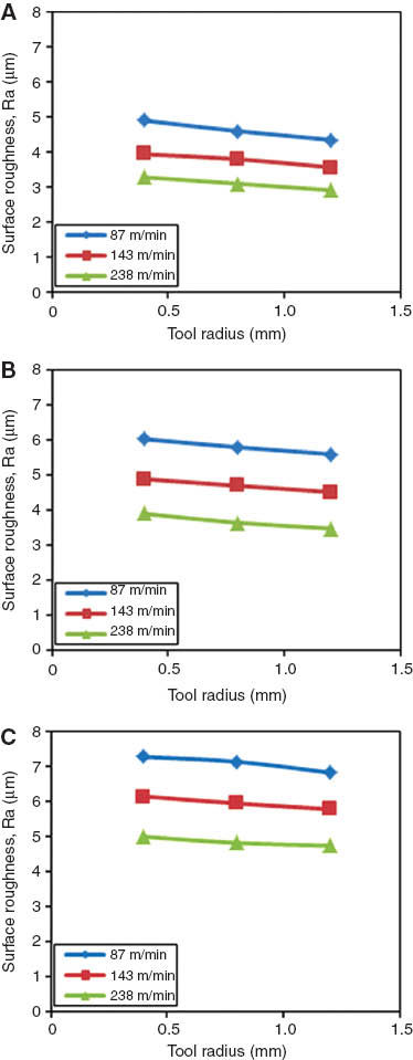
Effect of cutting speed on surface roughness; tool radius: (A) r=0.4 mm, (B) r=0.8 mm, and (C) r=1.2 mm.
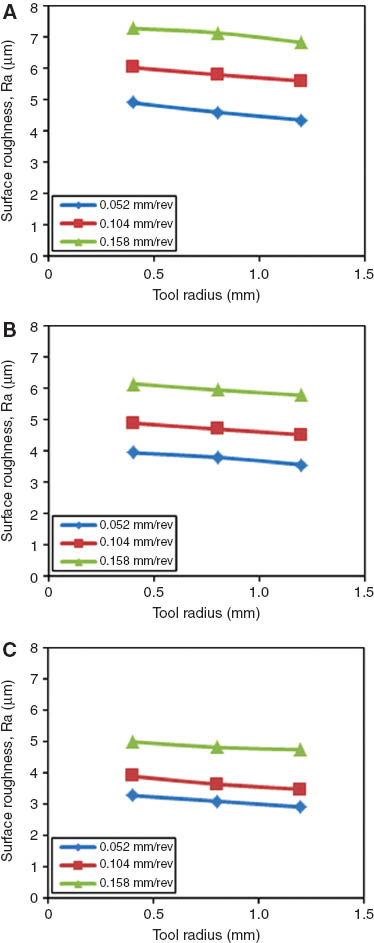
Effect of tool radius on surface roughness for various feed rates: (A) 0.052 mm/rev, (B) 0.104 mm/rev, and (C) 0.156 mm/rev.
Effect of tool radius on surface roughness for various cutting speeds: (A) 87 m/min, (B) 143 m/min, and (C) 238 m/min.

Effect of feed rate on cutting force for various tool radiuses: (A) r=0.4 mm, (B) r=0.8 mm, and (C) r=1.2 mm.

Effect of cutting speed on cutting force for various tool radiuses: (A) r=0.4 mm, (B) r=0.8 mm, and (C) r=1.2 mm.
3.1 Influence of feed rate and cutting speed on surface roughness
The surface roughness of the work-piece acquired after the manufacturing process is affected by various factors [7, 24], such as cutting parameters (speed, feed rate, and depth of cut), tool geometry (cutting edge angle, tool nose radius, etc.), tool materials (HSS, WC, PCD, etc), work materials, mechanical and thermal properties (work-piece hardness, tensile strength, elongation, thermal conductivity, etc.), cutting environment (dry, cutting fluid, MQL, etc.), and vibration [25]. Also, surface quality or roughness significantly affects the mechanical strength of components when they are subjected to fatigue cycles. Therefore, it is important to obtain an excellent surface quality for ensuring a higher performance in machined parts [7, 10, 12], which plays an important role in many fields [24].
In the literature, it has been pointed out that, compared with cutting speed and feed rate, the depth of cut plays a small role in machining composite material [15, 17]. This is because in the experiments accomplished, it had been found that as the depth of cut increased, it produced an incomplete machining at a faster traverse, which led to a higher surface roughness. Hence, according to this result, low limit of feed rates in machining GFRP composites may be suggested, as has been proposed in [15, 17, 25, 26]. Figure 2 shows the influence of cutting parameters on surface roughness with feed rates of 0.052, 0.104, and 0.156 mm/rev and tool nose radius of r=0.4, 0.8, and 1.2 mm.
As can be seen in Figure 2, feed rate (f) and insert radius (r) significantly affected surface quality. As the feed rate increased, the surface roughness increased, and conversely, the surface quality was reduced. Therefore, in finished GFRP composite materials, a low rate of surface roughness is desirable. As the graph evolutions (surface roughness vs. feed rate) were analyzed, it was noticed that the relationship between feed rate and surface roughness was not linear. The nonlinearity of correlation increased with the increase in cutting speed. The tool nose radius, on the other hand, insubstantially affected surface roughness, which may be considered as insignificant. A small increase was detected in surface roughness with the decrease in tool radius. The relationship between these three parameters for GFRP materials differs from the relationship found for metals due to their inhomogeneous microstructure. The inhomogeneity results in surface deformations and fractures at micro levels, e.g., fiber ends sticking out, peaks of deformed matrix material, and holes from debonding between fibers and matrix.
The relation between cutting speed and surface quality is depicted in Figure 3 for the three different tool’s radius. In this experiment, it was observed that surface roughness significantly decreased with the increase in cutting speed. As shown in Figure 3, the relationship between surface roughness and cutting speed is nonlinear and the nonlinearity increases with the increase in feed rate. These information revealed by the results found here aligned with the ones obtained through the studies carried out previously [13, 14, 16–19, 21]. These results imply that higher cutting speeds may cause very large deformation rates in glass fibers. Therefore, as in this experiment, the cutting speeds are kept low between 87 and 238 m/min, as in [17], to not experience any problem.
To some extent, the surface roughness, as is shown in Figure 3, can be improved by increasing the cutting speed. However, with extreme cutting speeds, due to the increase in heat in the material arising from surface friction, sometimes, deformations may crop up on the surface of finished composite material. These cross-correlations verified the results presented by Palanikumar et al. [26]. The increase in heat in the material causes softening of the material matrix and shearing. In this concept, contradictory results are available in the literature. While some colleagues are claiming that cutting speed significantly affects surface quality [13, 14, 16–19, 21, 22], some others are claiming that it does not affect significantly [6, 7, 15, 20, 22]. The inconsistency arises perhaps from the experimental environment and the tools used. Here, in this experiment, it was observed that the surface roughness decreases with the increase in cutting speed, which, in general, is in line with the reports found in [13].
Tool radius is a major factor that affects the surface roughness of the machined part [27]. As can be seen from Figures 4 and 5, for the same feed rates and cutting speeds, the increase in tool nose radius slightly decreased the surface roughness of GFRP composite pipe. This phenomenon may be speculated as follows: as the tool radius increases, the microscale vibration on the surface of the composite fiber under process decreases, and consequently, the surface roughness decreases. From Figure 4C, it can be seen that the maximum surface roughness value (7.28 μm) was obtained at 0.156 mm/rev feed rate, 87 m/min cutting speed, and 0.4 mm tool radius. A larger tool radius produced a smoother surface at lower feed rates and a higher cutting speed. It is because a large tool radius reduces damping at higher cutting speeds and thus leads to a better surface quality compared with a small tool radius. This result is similar to the results obtained by various researchers [25–28]. Therefore, it will be advantageous to use a tool with a large radius as much as possible while necessarily taking into account other factors such as tool wear [19].
3.2 Influence of feed rate and cutting speed on cutting force (Fc)
Cutting force plays a central role in machining process. Analysis of cutting force for proper planning and control of the machining operation as well as for optimization of the cutting conditions is essential. The dynamic stability, positioning accuracy of the tool, and roughness of the machined surface all together need to be optimized to improve the surface quality and, hence, the lifetime of the parts used in machining industry. A good optimization reduces production time cost. Accordingly, as a part of this work, a set of experiments were conducted to determine the effects of feed rate and cutting speed on cutting force. The variations observed in cutting force during turning GFRP composite pipe with three different cutting tool radiuses are presented in Figures 6 and 7.
It can be observed that the cutting force increases with the increase in feed rate for all cutting conditions, and conversely, the cutting force decays out with the increase in cutting speed (Figures 6 and 7). These results do agree with the results presented by Hussain et al. [6] and with the manufacturing practice. These relationships, similar to the results mentioned above, are nonlinear relationships. The consistency between the curves in each figure seems to be much irregular, particularly for higher tool radius values (r=1.2 mm). These results also show the impact of tool radius on the machining of GFRP composite materials. From these results, it can be concluded that high cutting speed and low feed rate should be preferred for turning of GFRP composite pipes.
4 Conclusions
Composite materials have inhomogeneous and anisotropic structures. Owing to these properties, they are produced to have a near-net shape. As secondary process, machining is conducted to obtain surface quality and dimensional accuracy. Further machining operations such as turning, milling, and drilling are the commonly used processes in industrial applications. Due to the inhomogeneity and anisotropic structures of GFRPs, during turning, some problems may be encountered with the work-piece, which generally reflects on to its surface. Main factors affecting surface roughness are cutting parameters. The objective of this study was to investigate the effect of cutting parameters on cutting force and surface roughness of GFRP composites using cutting tools having different nose radius. From the experimental results obtained in this particular study, the followings can be concluded.
In the machining of GFRP, particular conclusions emerge, as follows:
Decrease in feed rate improves surface roughness and, hence, surface quality.
Surface roughness decreases with the increase in cutting speed.
Surface roughness is highly influenced by feed rate.
For similar feed rates and cutting speeds, an increase in tool nose radius decreases surface roughness.
Cutting force increases with the increase in feed rate for all cutting conditions.
An increase in cutting speed decreases cutting force.
An increase in tool nose radius decreases cutting force.
Considering everything, it was understood that for obtaining a good surface quality, high cutting speeds and low feed rates should be preferred in turning of GFRP composite pipes.
References
[1] Callister WD Jr. Materials Science and Engineering: An Introduction, 4th ed., John Wiley & Sons, Inc.: New York, USA, 1997.Search in Google Scholar
[2] Kilickap E. J. Compos. Mater. 2011, 45, 727.10.1177/0021998310381539Search in Google Scholar
[3] Chang C-S. J. Mater. Process. Technol. 2006, 180, 117–129.10.1016/j.jmatprotec.2006.05.011Search in Google Scholar
[4] Palanikumar K, Karunamoorthy L, Vinoth C, Veeinthra Muthu S. On the Machining of Glass Fiber Reinforced Composite Pipes, Proceedings of the International Conference on Mechanical Engineering 2003 (ICME2003), 26–28 December 2003, Dhaka, Bangladesh.Search in Google Scholar
[5] Everstine GC, Rogers TG. J. Compos. Mater. 1971, 5, 94–106.10.1177/002199837100500109Search in Google Scholar
[6] Hussain SA, Pandurangadu V, Palanikumar K. Int. J. Eng. Sci. Technol. 2011, 3, 103–118.10.4314/ijest.v3i4.68546Search in Google Scholar
[7] Eriksen E. Int. J. Mach. Tools Manuf. 1999, 39, 1611–1618.10.1016/S0890-6955(99)00017-6Search in Google Scholar
[8] Kalla D, Sheikh-Ahmad J, Twomey J. Int. J. Mach. Tools Manuf. 2010, 50, 882–891.10.1016/j.ijmachtools.2010.06.005Search in Google Scholar
[9] Naveen Sait A, Aravindan S, Noorul Haq A. Int. J. Adv. Manuf. Technol. 2009, 43, 581–589.10.1007/s00170-008-1731-ySearch in Google Scholar
[10] Vijaya Kini M, Chincholkar AM. Mater. Des. 2010, 31, 3590–3598.10.1016/j.matdes.2010.01.013Search in Google Scholar
[11] Davim JP, Gaitonde VN, Karnik SR. J. Mater. Process. Technol. 2008, 205, 16–23.10.1016/j.jmatprotec.2007.11.082Search in Google Scholar
[12] Feng CX, Wang X. Int. J. Adv. Manuf. Technol. 2002, 20, 348–356.10.1007/s001700200162Search in Google Scholar
[13] Khan MA, Kumar AS. J. Manuf. Processes 2011, 13, 67–73.10.1016/j.jmapro.2010.10.002Search in Google Scholar
[14] Davim JP, Mata F. Mater. Des. 2007, 28, 1050–1054.10.1016/j.matdes.2005.09.019Search in Google Scholar
[15] Fetecau C, Stan F. Measurement 2012, 45, 1367–1379.10.1016/j.measurement.2012.03.030Search in Google Scholar
[16] Davim JP, Mata F. Int. J. Adv. Manuf. Technol. 2005, 26, 319–323.10.1007/s00170-003-2006-2Search in Google Scholar
[17] Palanikumar K. Mater. Des. 2007, 28, 2611–2618.10.1016/j.matdes.2006.10.001Search in Google Scholar
[18] Santhanakrishnan G, Krishnamurthy R, Malhotra SK. J. Mech. Working Technol. 1988, 17, 195–204.10.1016/0378-3804(88)90021-6Search in Google Scholar
[19] Ramulu M, Arola D, Colligan K. Eng. Syst. Des. Anal. ASME 1994, 2, 93–101.Search in Google Scholar
[20] An S-O, Lee E-S, Noh S-L. J. Mater. Process. Technol. 1997, 68, 60–67.10.1016/S0924-0136(96)02534-4Search in Google Scholar
[21] Davim JP, Reis P, Conceiçao Antonio C. Compos. Struct. 2004, 64, 493–500.10.1016/j.compstruct.2003.09.054Search in Google Scholar
[22] Darlewski J, Gunthe U. Plaste Kautschuk 1976, 23, 911–917.Search in Google Scholar
[23] Palanikumar K, Davim JP, J. Mater. Process. Technol. 2009, 209, 511–519.10.1016/j.jmatprotec.2008.02.020Search in Google Scholar
[24] Kilickap E. J. Reinf. Plast. Compos. 2010, 29, 3498–3503.10.1177/0731684410386271Search in Google Scholar
[25] Altintas Y, Weck M. Ann. Manuf. Technol. 2004, 53, 619–642.10.1016/S0007-8506(07)60032-8Search in Google Scholar
[26] Palanikumar K, Karunamoorthy L, Karthikeyan R. Mater. Des. 2006, 27, 862–871.10.1016/j.matdes.2005.03.011Search in Google Scholar
[27] Dogra M, Sharma VS, Dureja J. J. Eng. Sci. Technol. Rev. 2011, 4, 1–13.Search in Google Scholar
[28] Işık B. Int. J. Adv. Manuf. Technol. 2008, 37, 42–48.10.1007/s00170-007-0946-7Search in Google Scholar
©2016 by De Gruyter
This article is distributed under the terms of the Creative Commons Attribution Non-Commercial License, which permits unrestricted non-commercial use, distribution, and reproduction in any medium, provided the original work is properly cited.
Articles in the same Issue
- Frontmatter
- Review
- The behaviour of aluminium matrix composites under thermal stresses
- Original articles
- Preparation and characterization of graphite/resin composite bipolar plates for polymer electrolyte membrane fuel cells
- Synergistic effect of carbon nanotubes in combination with magnesium hydroxide on the flame retardant poly(ethylene-co-vinyl acetate)
- Preparation and characterization of nano biphasic calcium phosphate/poly-L-lactide composite scaffold
- Durability study of ramie fiber fabric reinforced phenolic plates under humidity conditions
- Synthesis and molecular dynamics simulation of hyperbranched poly(amine-ester)/neodymium nanocomposites
- Investigation on wear properties of AZ31-MWCNT nanocomposites fabricated through mechanical alloying and powder metallurgy
- Probabilistic analysis of a thermosetting pultrusion process
- Analysis of shrinkage and creep behaviors in polymer-coated lightweight concretes
- Investigation of optimum cutting parameters and tool radius in turning glass-fiber-reinforced composite material
- Buckling and vibration analyses of composite laminates with weak interfaces by a coupled meshfree and finite element method
- Free vibration and postbuckling of laminated composite Timoshenko beams