Robot visual navigation estimation and target localization based on neural network
-
Yanping Zhao
 und
Edeh Michael Onyema
und
Edeh Michael Onyema

Abstract
The high computational cost, complex external environment, and limited computing resources of embedded system are some major problems in traditional autonomous robot navigation methods. To overcome these problems, a mobile robot path planning navigation system based on panoramic vision was proposed. This method first describes the structure and functions of the navigation system. It explains how to use the environment to explore and map in order to create a panoramic vision sensor. Finally, it elaborates on the breadth-first search based on regression neural network (RNN) method, the Voronoi skeleton diagram method, the algorithm principle, and how to navigate by the planning path implementation of practical strategies. The simulation results illustrate that the breadth-first search method and the Voronoi skeleton graph method based on panoramic view have a high speed. The accessibility of RNN planning algorithm can effectively solve the difficult problems such as high computing overhead, complex navigation environment, and limited computing resources. In the actual robot navigation experiment, the difference in real-time performance and optimality performance that exists between the two algorithms is reflected in the length and duration of the course taken by the robot. When applied to a variety of site environments, the breadth-first search method requires between 23.2 and 45.3% more time to calculate the planned path than the Voronoi skeleton graph method, despite the fact that the planned path length is between 20.7 and 35.9% shorter using the breadth-first search method. It serves as a guide for choosing the appropriate algorithm to implement in practical applications.
1 Introduction
Navigation technology is the core of mobile robot research and also the key technology for mobile robot to achieve complete autonomy and intelligence. Navigation refers to the autonomous movement of the mobile robot, which senses the environment and its own state through sensors to search for an optimal or approximate optimal path without collision in the environment with obstacles. Navigation technology needs to solve two problems: (i) find effective and practical sensor detection means and processing methods and establish environmental map model; (ii) use a fast and effective path planning algorithm to find an optimal or approximately optimal safe path. Among many environmental detection sensors, panoramic vision sensor has the advantages of wide signal detection range and fast and complete information acquisition. Only one camera can be used to observe the robot as the center of a 360° panoramic environment with a certain radius, which not only quickly obtain environmental information but also greatly reduce the complexity of system design. Obviously, this is an effective means of building environmental maps. Traditional path planning methods, such as artificial potential field method, realize the path planning of mobile robots by forming virtual repulsive force by obstacles and virtual gravitation force by objects. However, it is easy to form unexpected local potential well, which may lead to the failure of planning in complex environment. However, the planning method based on regression neural network (RNN) has high parallelism and rich dynamic properties, which have been widely used in the fields of intelligent logistics, robotic arm handling, and mobile grabbing [1].
Techniques for robot visual navigation are shown in Figure 1. Outdoor robot operations are mostly equipped with visual perception equipment for robot positioning, self-state estimation, and obstacle detection [2,3]. Most indoor robot operations use the simultaneous localization and mapping method. The robot performs mapping and positioning in an unfamiliar environment at the same time [4]. Although this method has high accuracy, it has problems such as cumulative errors and excessive calculations. Moreover, according to the obtained environmental information, it is also a difficult problem to design logic to get the optimal navigation instructions. Bison et al. [5] of Google’s Deepmind project team proposed a “behavior-comment” model-free algorithm based on deterministic policy gradients, which improves the generalization of the algorithm. Tejera et al. [6] of Stanford University improved the “behavior-comment” algorithm, proposed the AI2-THOR framework to provide realistic scenes and physics engine environments, and provided a large number of experimental samples to improve the effect of the algorithm. Pal et al. [7] of Carnegie Mellon University proposed a three-layer backpropagation network ALVINN in 1988. ALVINN takes images from cameras and laser rangefinders as input and generates the direction in which the vehicle should travel as output, so that Follow the path. Experiments show that under certain field conditions, the network can effectively follow the actual road. Delarboulas et al. [8] of Carnegie Mellon University used professional drone pilots to operate a collection of data sets for training in different environments and extracted feature information from images obtained by monocular cameras for visual navigation to avoid trees in the forest in visual navigation flight. Pleshkova et al. [9] of ETH Zurich produced a data set of paths in the forest and designed an eight-layer neural network as a classifier. The pictures obtained by the monocular camera can directly obtain the navigation direction through the neural network. The plane flew along the path in the woods. Peng et al. [10] improved the above method [8] and proposed an 18-layer network TrailNet with two classifiers. The original image obtained by the monocular camera is used as input, and in addition to directly outputting the navigation direction, it is also outputting its position relative to the center of the path that enhances the robustness of the algorithm. The article also uses the YOLO [11] detection algorithm for pedestrian detection, achieving the effects of visual navigation and target detection.
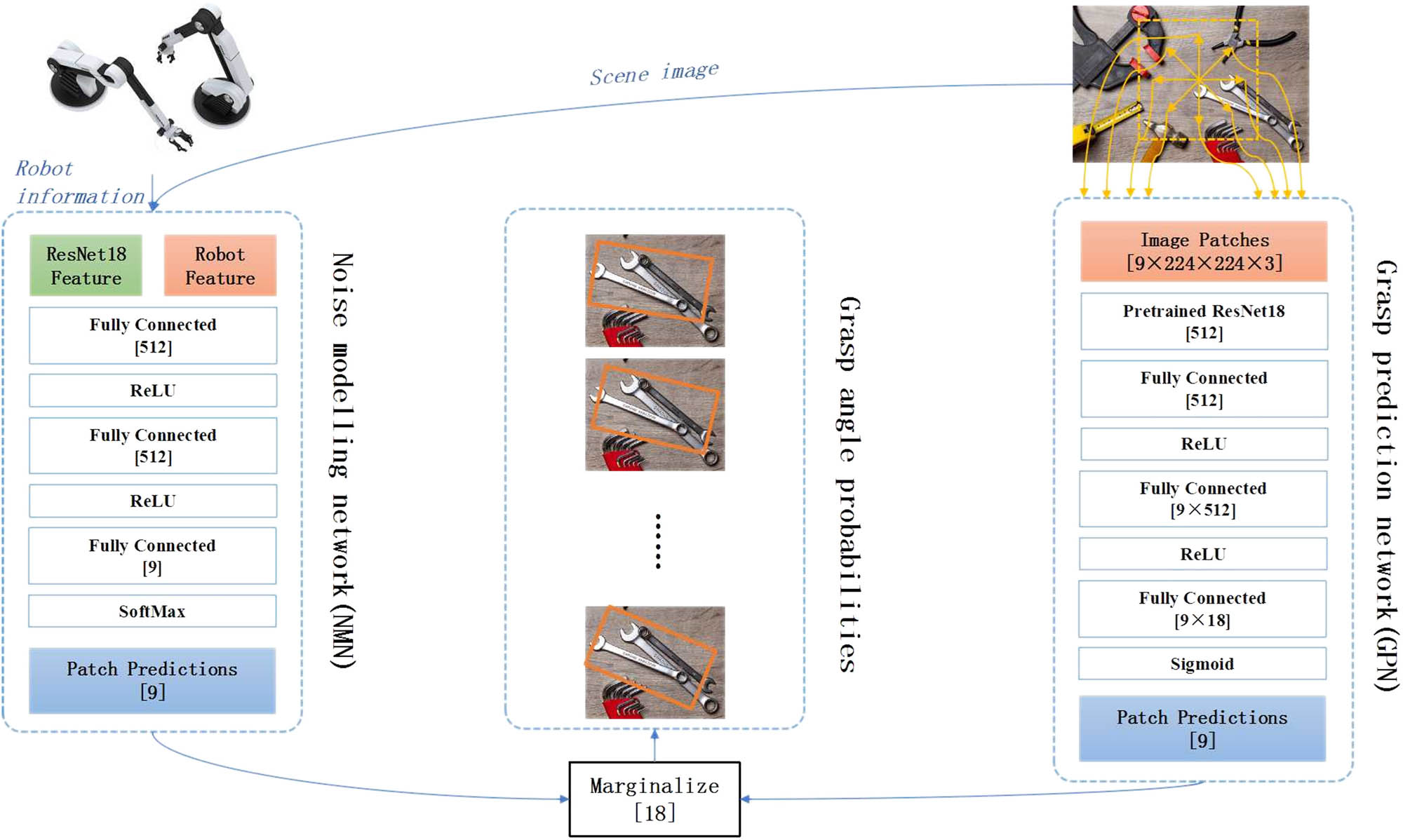
Design of robot visual navigation based on neural network.
The main work of this article focuses on the design and implementation of a mobile robot navigation system based on full-dimensional vision. The system has the functions of establishing a global environment map, planning a path, and guiding the robot to navigate. Its open structure and good man–machine interface facilitate software expansion and system debugging and are an important part of the practical application of mobile robot navigators [12]. As shown in Figure 1, the navigation system has three core modules: (i) the map creation module communicates with the panoramic vision sensor, and after receiving the image information, it analyzes and processes the obstacle information and extracts the obstacle information, and in the internal global map record the location of obstacles on the upper; (ii) path planning module, built-in two planning algorithms based on RNN, which can quickly find an optimal or feasible path based on global map information; (iii) navigation module, which can be called the path planning module performs offline or online path planning, and then according to the path node sequence output by the path planning module, the navigation task is decomposed into a sequential state sequence, and the switching between states is used to indicate the switching between path points, and the mobile robot is controlled to implement the navigation task. The design and implementation of each module of the navigation system are described in Figure 2.

System block diagram of navigation system.
This article first describes the architecture of the navigation system and then discusses how to use the panoramic vision sensor to explore the environment and build a global map; the breadth-first search based on the RNN and the Voronoi skeleton diagram planning algorithm principle; and how to realize the three navigations according to the planned path. The aspects are elaborated in detail. Finally, through experiments on the Jiaolong mobile robot platform, the effectiveness of the navigation system is evaluated, and the two planning algorithms are analyzed, compared, and discussed.
Over the course of the last few decades, deep learning-based approaches have garnered an increasing amount of interest from the researchers because of their advancement. These methods are utilized in a wide variety of fields, including the medical field [13,14,15], the industrial field [16,17,18,19], and many others. Nair et al. [20] have presented a technique based on blockchains with the goal of reducing the amount of energy used. When planning the route of a robot, a large amount of computing is necessary, which in turn requires a highly customizable system and results in the generation of a great deal of power. By utilizing the blockchain technology, this energy usage can be reduced to a significant extent.
Capi et al. [21] presented a strategy to navigating robots that is based on a neural network’s path planning. This method utilizes global positioning satellites (GPS) and a compass sensor to guide the robot from its starting place to its final destination. In order to go from the origin location to the destination point, a deep neural network is trained using GPS and sensor data.
Djenouri et al. [22] have proposed an approach for visual navigation for the industry platform that is based on Deep Learning. In the manufacturing sector, computer-aided design software or engineering drawings are utilized to locate the equipment. In this study, an image-based navigation system was developed. This system made use of a convolution neural network, often known as CNN, to extract relevant characteristics. These features were then utilized to build clusters. The image is separated within the cluster by using local features and between clusters by using global features correspondingly.
A deep learning-based navigation system for the mobile robot, specifically for use in an indoor environment, was presented by Foroughi et al. [23]. Where a CNN is used to extract features from an image, a deep learning model is first trained on the topological maps of the actual environment and then combination of CNN and topological map is employed to calculate the distance to and location of the mobile robot.
2 Research methods
2.1 Map creation based on panoramic vision
The traditional visual detection method mainly uses the conventional lens camera to directly obtain the scene information [24]. The main problem of this method is that the angle of view is small, and only partial information with a limited field of view can be obtained. In order to obtain a large field of view scene image, a panoramic image can only be obtained through a single lens rotation or a horizontal combination of multiple ordinary lenses. Therefore, the system design is complicated and the real-time operation is poor [25].
Panoramic vision technology uses the principle of optical reflection to expand the field of view of the vision system. In a panoramic vision system, the camera device does not directly view the external environment, but faces a convex mirror (panoramic viewfinder), which is generally installed directly above the camera device lens [26]. According to the principle of mirror reflection, the light emitted by distant objects passes through the lens of the imaging device after being reflected by the mirror, forming a panoramic image of the object within a certain radius centered on the robot (i.e., panoramic vision). Then, the region of interest in the image can be extracted according to the color range, and the characteristics of these regions of interest (such as location, area, obstacle distance, etc.) can be recorded for analysis. Therefore, only one camera can observe the 360° panoramic environment around the robot, which can quickly and accurately detect the surrounding environment information, while greatly reducing the complexity of the system design [27].
The map creation process is as follows: first, the vision processing software receives the digital image information of the panoramic vision system, and then performs image processing (enhancement, restoration, coding); then, the preprocessed data are passed to the map creation module of the navigator. This module uses the blob algorithm for image recognition (segmenting the image into different regions and performing feature extraction and classification) [28] and extracts the position information of the obstacle in the local coordinate system of the robot body; finally, the obstacle in the global position in the map is converted into a binary raster map.
2.2 Path planning module based on RNN
After the raster map is created, how to choose a suitable path planning algorithm is very important. For the navigation tasks of mobile robots, algorithms need to meet high requirements in terms of real-time, effectiveness, and path safety. The planning algorithm based on the recurrent neural network is not more than a good solution. The model mechanism and two search algorithms are described below.
RNN has a high degree of parallelism and rich dynamic characteristics [29]. For the two-dimensional bounded environment represented by the grid map, the neurons of the RNN are mapped to the grid one by one. Thus, the local connectivity between neurons represents the connectivity of the grid environment. In this article, it is defined that each neuron in the RNN is connected to the surrounding eight neighboring neuron nodes, which constitutes an eight-connected neighborhood.
2.2.1 Breadth-first search algorithm
The algorithm first uses the sequential raster scanning method to obtain the eight-connected distance from each node of the RNN to the nearest obstacle node and then designs a safe path function, selects the safety parameters according to the radius of the robot body, and uses this function to inhibit the nerves near the obstacle. The meta-node connection weight increases the cost of the robot passing through the area near the obstacle [30]. When a stable neuron state output potential field is established in the RNN, starting from the starting node, search for the adjacent non-obstacle node with the largest output, and then expand to outer nodes in the order of breadth-first traversal until the end of the search to the target node. If there is a feasible path between the starting node and the target node, the algorithm can ensure that the path can be obtained through one search, and the algorithm complexity is only O(N).
The design of the safe path function f(d i ) is as follows [31]: first select the safe distance threshold D safe according to the grid size when discretizing the environment and the size of the robot itself, and then use the sequential raster scanning method to calculate the non-obstacle neurons. The d i represent the eight-connected distance from node i to the nearest obstacle neuron. When d i is not greater than D safe, the robot cannot pass through the node, f(d i ) = +∞; if d i is greater than D safe, it can pass through the node. The function of the parameter k s is to restrict the planned path from passing through the narrow and long passage as much as possible. Its formula is represented by the following equation:
2.2.2 Voronoi skeleton diagram algorithm
The Voronoi diagram is a collection of axes in the non-obstacle space. Therefore, the dimension of the Voronoi diagram is much lower than that of the robot workspace. If only the Voronoi diagram is used for path planning, the search time can be greatly reduced. However, the path redundancy based on Voronoi diagram planning is high, so if the path length is used as the performance index, the optimality of the algorithm is poor. However, in practical applications, the safety of robot motion needs to be fully considered, and the use of Voronoi diagram can ensure that the robot motion has a wider channel.
All obstacle neurons on the RNN form a set, where the junctions of the “ruling” areas of different neurons are local minimum points along the horizontal or vertical direction. These extremes are found through local comparison, refinement, and extension operations. Form small value points, connect these points to construct a Voronoi skeleton diagram, and then use the breadth-first search method to find a feasible path in the set of neuron nodes belonging to the skeleton diagram.
2.2.3 Navigation module
The main function of the navigation module is according to the map information constructed by the map creation module call the path planning module for offline or online planning, obtain the output path node sequence, and then interpret it into a sequence state sequence to control the robot to implement navigation [32].
Then, the execution process of navigation as a sequential state sequence is described through the specific method as follows: define a number of states, each state contains a number of basic behaviors, such as movement to the target behavior. These behaviors take the current path node as the target gravitational vector and produce the corresponding behaviors to guide the robot to move forward. After judging whether the robot has reached the current path node through the real-time information fed back by the self-positioning module (such as the odometer), the event triggers the migration of the current behavior state to the next behavior state and generates the behavior of moving forward to the next path node, until reaching the target area. Thus, the execution process of navigation can be described as a state machine with states as nodes and event triggers as transitions [33].
3 Research results
The map exploration method based on panoramic vision can quickly and accurately locate obstacles in the environment; at the same time, the path planning method based on RNN can ensure the reachability of the optimized path [34]. The following will use the Jiaolong mobile robot to design experiments. For the same environmental map and the same starting point and target point, the breadth-first search method and the Voronoi skeleton diagram method are used for path planning and navigation to verify the effectiveness of the navigation system, and analyze and compare the planning performance of the two algorithms.
The navigation system software is installed in the upper computer of the “Jiaolong” mobile robot. The machine is configured as a notebook computer with a P41.4 GHz frequency and 256 M memory. Table 1 shows the environment and task parameters.
Environment and task parameters
| Environment variable | Parameter |
|---|---|
| Map size (grid) | 200 × 200 |
| Grid area (mm × mm) | 100 × 100 |
| Starting point coordinates | (77,151) |
| Target point coordinates | (9,171) |
Aiming at the breadth-first search method, in order to ensure the safety of the path, two sets of safety parameters are experimentally designed to verify its influence on the planned path [35]. The safe distance threshold D safe in Table 2 reflects the degree of inhibition of the neuron connection weight near the obstacle, and the function of k s is to restrict the planned path from passing through the narrow and long channel as much as possible. The Voronoi skeleton diagram method does not require pre-set safety parameters.
Planning performance of the two algorithms
| Algorithm type | D safe | k s | Path length (Grid) | Algorithm time-consuming (ms) |
|---|---|---|---|---|
| Breadth first 1 (Figure 3) | 3 | 8 | 93 | 30 |
| Breadth first 2 (Figure 4) | 5 | 12 | 115 | 42 |
| Voronoi | None | None | 145 | 23 |
The navigation trajectory of the “Jiaolong” robot under the two planning algorithms is shown in Figures 2–5. The black squares are obstacles obtained by panoramic vision exploration, and the black lines are the trajectory of the robot according to the planned path. It can be seen that for relatively wide and long obstacles, the two algorithms based on RNN avoid the local minima problem of the traditional potential field method, and avoid planning to fall into a local potential well.
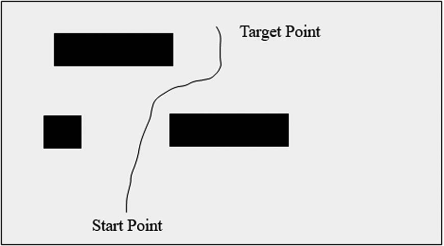
The planning path of breadth-first search (1).

The planning path of breadth-first search (2).

Voronoi skeleton diagram method planning path.
Table 2 shows the planning performance of the two algorithms. The breadth-first search method takes different safety parameters to obtain paths with different safety. When D safe is 3 and k s is 8, the path is the shortest but closer to the obstacle. When D safe is 5 and k s is 12, the path is longer, but navigation along narrow passages is avoided. The Voronoi method, as stated in its principle [36], can generate a path along the central axis of free space, fully guaranteeing the safety of the robot, and the search time is shorter than the breadth-first method, but the path redundancy is greater. Record the time consumed by the two algorithms to plan the path and calculate the average time consumption of the algorithm based on this. The time-consuming record of the Voronoi skeleton diagram method planning path algorithm is shown in Figure 6.

Time-consumption of Voronoi skeleton diagram method planning path algorithm.
The experiment proves the effectiveness of the navigation software and verifies the difference in real-time and optimality of the two path planning algorithms. According to Table 2, it can be calculated that the breadth-first search method is better than the Voronoi skeleton in different site environments. It takes 23.2–45.3% more time to calculate the planned path by graph method, but the length of the planned path is 20.7–35.9% less. The appropriate algorithm should be selected according to different needs.
4 Conclusion
This article introduced the design and implementation of a navigation system for path planning based on panoramic vision, which uses the Jiaolong mobile robot to design a navigation task for an experiment in a real environment. The experimental results demonstrate the effectiveness of panoramic vision navigation, as well as RNN-based planning algorithm and the two search algorithms: breadth-first search method and Voronoi skeleton diagram method in real-time. The difference in optimal performance provides guidance for how to choose algorithms in practical applications. The experiment results show that breadth-first search method takes 23.2–45.3% more time to calculate the planned path as compared to the Voronoi skeleton graph method.
The future research direction can start from reducing the path length of the Voronoi skeleton diagram method and the calculation time-consuming of the breadth-first search method.
-
Funding information: None declared.
-
Author contributions: Y.Z. decide the methodology and wrote the paper; R.K.G conceived and performed the research and formal analysis, help in paper drafting; E.M.O. analyzed the data and perform the visualization.
-
Conflict of interest: Authors state no conflict of interest.
-
Informed consent: Informed consent was obtained from all individuals included in this study.
-
Ethical approval: The research related to human use has been complied with all the relevant national regulations, institutional policies and in accordance the tenets of the Helsinki Declaration, and has been approved by the authors’ institutional review board or equivalent committee.
-
Data availability statement: All data used in the manuscript is publicly available.
References
[1] H. Tang, S. Shi, Y. Chen, and Z. Peng, “Improved algorithm of robot simultaneous localization and mapping based on neural network PID,” J. Shaoyang Univ. (Nat. Sci. Ed.), vol. 28, pp. 70–78, 2017.Suche in Google Scholar
[2] A. Datta and K. C. Yow, “A fast learning neural network for oriented visual place map-based robot navigation,” In: The Proceeding of IEEE International Conference on Systems, Man, and Cybernetics, 2011.10.1109/ICSMC.2011.6084054Suche in Google Scholar
[3] H. Kanayama, T. Ueda, H. Ito, and K. Yamamoto, “Two-mode mapless visual navigation of indoor autonomous mobile robot using deep convolutional neural network,” In: The Proceedings of IEEE/SICE International Symposium on System Integration (SII), 2020.10.1109/SII46433.2020.9025851Suche in Google Scholar
[4] V. A. Kulyukin, US patent, multi-sensor wayfinding device. Patent number US20070018890 A1, 2007. https://patents.google.com/patent/US20070018890.Suche in Google Scholar
[5] P. Bison, G. Chemello, and C. Sossai, Logic-based algorithms for data interpretation with application to robotics, Semantic scholars, 1998. https://www.semanticscholar.org/paper/Logic-based-algorithms-for-data-interpretation-with-Bison-Chemello/e4179271d5d818c5ca1cdcf88441aa272f573147.Suche in Google Scholar
[6] G. Tejera, A. Barrera, J. M. Fellous, M. Llofriu, and A. Weitzenfeld, “Spatial cognition: robot target localization in open arenas based on rat studies,” SPIE Conference on Multisensor, Multisensor, Multisource Information Fusion: Architectures, Algorithms, and Applications, 2013.10.1117/12.2020050Suche in Google Scholar
[7] N. R. Pal, N. Kasabov, R. K. Mudi, S. Pal, and S. K. Parui, “Neural information processing,” In: Proceedings of the 11th International Conference, ICONIP, 2004.10.1007/b103766Suche in Google Scholar
[8] P. Delarboulas, P. Gaussier, R. Caussy, and M. Quoy, “Robustness study of a multimodal compass inspired form HD-Cells and Dynamic neural fields,” International Conference on Simulation of Adaptive Behavior, Cham, Springer, 2014.10.1007/978-3-319-08864-8_13Suche in Google Scholar
[9] S. Pleshkova, A. Bekiarski, S. S. Dehkharghani, and K. Peeva, “Perception of audio-visual information for mobile robot motion control systems,” Intell. Syst. Ref. Library, vol. 75, pp. 135–167, 2015.10.1007/978-3-319-11430-9_6Suche in Google Scholar
[10] S. Peng, W. Xinhua, and Y. Yurong, “Real-time onboard mapping and localization of an indoor MAV using laser range finder,” In: Proceedings of the 4th International Conference on Information Science and Control Engineering (ICISCE), 2017.10.1109/ICISCE.2017.336Suche in Google Scholar
[11] H. U. Wen and R. L. Sun, “Visual localization and motion estimation based on sequential images,” Transducer Microsyst. Technol., vol. 26, no. 7. pp. 48–53, 2007.10.1080/07474940601112336Suche in Google Scholar
[12] S. Shah, “Single camera-based vision systems for ground and; aerial robots.” Dissertations & Theses – Gradworks, 2010.Suche in Google Scholar
[13] D. B. Singh, M. K. Gupta, D. V. Singh, S. K. Singh, and K. Misra, “Brain tumor detection and classification using cycle generative adversarial networks,” Interdiscip. Sci. Comput. Life Sci., vol. 17, no. 1. pp. 1–17, 2022.Suche in Google Scholar
[14] R. K. Gupta, P. Gautam, R. K. Pateriya, P. Verma, and Y. Sahu, “COVID-19 lesion segmentation and classification of lung CTs using GMM-based hidden Markov random field and ResNet 18,” Int. J. Fuzzy Syst. Appl., vol. 11, no. 2. pp. 1–21, 2022.10.4018/IJFSA.296587Suche in Google Scholar
[15] V. Roy, S. Shukla, P. K. Shukla, and P. Rawat, “Gaussian elimination-based novel canonical correlation analysis method for EEG motion artifact removal,” J. Healthc. Eng., vol. 2017, pp. 1–11, 2017.10.1155/2017/9674712Suche in Google Scholar PubMed PubMed Central
[16] C. Xie, R. Zhang, and J. Bhola, “Research on fault detection and identification methods of nonlinear dynamic process based on ICA,” Nonlinear Eng., vol. 23, pp. 479–90, 2022.10.1515/nleng-2022-0003Suche in Google Scholar
[17] H. Durur, A. Yokuş, and K. A. Abro, “Computational and traveling wave analysis of Tzitzéica and Dodd-Bullough-Mikhailov equations: An exact and analytical study,” Nonlinear Eng., vol. 10, pp. 272–81, 2021.10.1515/nleng-2021-0021Suche in Google Scholar
[18] A. Kaya and A. Bozkurt, “Determining optimum location and sizing of distributed generation systems in a real radial distribution network,” Elect. J., vol. 21, no. 3. pp. 342–51, 2021.10.5152/electrica.2021.21038Suche in Google Scholar
[19] D. Ersoy and B. Erkmen, “A Stochastic computing method for generating activation functions in multilayer feedforward neural networks,” Elect. J., vol. 21, no. 3. pp. 376–87, 2021.10.5152/electr.2021.21043Suche in Google Scholar
[20] R. Nair, S. Gupta, M. Soni, P. K. Shukla, and G. Dhiman, “An approach to minimize the energy consumption during blockchain transaction,” Material Today Proceeding, 2020, pp. 1–6.10.1016/j.matpr.2020.10.361Suche in Google Scholar
[21] G. Capi, S. Kaneko, and B. Huaa, “Neural network based guide robot navigation: An evolutionary approach,” Proc. Computer Sci., vol. 76, pp. 74–9, 2015.10.1016/j.procs.2015.12.279Suche in Google Scholar
[22] Y. Djenouri, J. Hatleskog, J. Hjelmervik, E. Bjorne, T. Utstumo, and M. Mobarhan, “Deep learning-based decomposition for visual navigation in industrial platforms,” Appl. Intell., vol. 52, pp. 8101–17, 2002.10.1007/s10489-021-02908-zSuche in Google Scholar
[23] F. Foroughi, Z. Chen, and J. Wang, “A cnn-based system for mobile robot navigation in indoor environments via visual localization with a small dataset,” World Electr. Veh. J., vol. 12, pp. 1–22, 2021.10.3390/wevj12030134Suche in Google Scholar
[24] M. A. El-Dosuky, M. Z. Rashad, T. T. Hamza, and A. H. El-Bassiouny, “Simulated tom thumb, the rule of thumb for autonomous robots.” Computer Sci., Arxiv, 2012. https://arxiv.org/abs/1210.2421.Suche in Google Scholar
[25] J. Faigl, V. Vonásek, and L. Přeučil, “Visiting convex regions in a polygonal map,” Robot. & Auto. Syst., vol. 61, no. 10. pp. 1070–1083, 2013.10.1016/j.robot.2012.08.013Suche in Google Scholar
[26] R. M. Jusoh, “Development of a vision-based mobile robot navigation system for golf balls detection and location,” 2007. http://psasir.upm.edu.my/id/eprint/587/.Suche in Google Scholar
[27] J. Xin, X. L. Jiao, Y. Yang, and D. Liu, “Visual navigation for mobile robot with kinect camera in dynamic environment,” The 35th Chinese Control Conference (CCC), 2016. 10.1109/ChiCC.2016.7554091.Suche in Google Scholar
[28] D. Fu, H. Xia, and Y. Qiao, “Monocular visual-inertial navigation for dynamic environment,” Remote. Sens., vol. 13, pp. 1–19, 2021.10.3390/rs13091610Suche in Google Scholar
[29] A. Rosenfeld, Vision-Based Navigation and Recognition, 1998. https://apps.dtic.mil/sti/pdfs/ADA351722.pdfSuche in Google Scholar
[30] M. Chancán and M. Milford, “Robot perception enables complex navigation behavior via self-supervised learning,” Arxiv. 2020. https://arxiv.org/abs/2006.08967.Suche in Google Scholar
[31] Y. Wu, N. Sang, W. Lin, Y. Shao, “Joint image restoration and location in visual navigation system,” In: The Proceedings of Automatic Target Recognition & Navigation, 2018.10.1117/12.2284978Suche in Google Scholar
[32] L. Hoyer, C. Steup, and S. Mostaghim, “A robot localization framework using CNNs for object detection and pose estimation,” In: The Proceedings of IEEE Symposium Series on Computational Intelligence (SSCI), 2018.10.1109/SSCI.2018.8628752Suche in Google Scholar
[33] J. Zhao and G. P. Liu, “A novel localization method for indoor mobile robot based on odometry and ceiling visual features,” In: The Proceedings of 34th Chinese Control Conference (CCC), 2015.Suche in Google Scholar
[34] C. L. Hwang and J. Y. Huang, “Neural-network-based 3-D localization and inverse kinematics for target grasping of a humanoid robot by an active stereo vision system,” In: The Proceedings of International Joint Conference on Neural Networks, 2012.10.1109/IJCNN.2012.6252400Suche in Google Scholar
[35] L. Zu, Y. Peng, S. Hao, and L. Chen, “Sound source target localization system of mobile robot,” In: The Proceedings of International Conference on Control Automation Robotics & Vision, 2011.Suche in Google Scholar
[36] H. Hajjdiab and R. Laganiere, “Vision-based multi-robot simultaneous localization and mapping,” In: The Proceedings. of First Canadian Conference on Computer and Robot Vision, 2004.10.1109/CCCRV.2004.1301439Suche in Google Scholar
© 2022 Yanping Zhao et al., published by De Gruyter
This work is licensed under the Creative Commons Attribution 4.0 International License.
Artikel in diesem Heft
- Regular Articles
- Social robot – Jack of all trades?
- Opportunities for social robots in the stuttering clinic: A review and proposed scenarios
- Social inclusion of robots depends on the way a robot is presented to observers
- Special Issue: Recent Advancements in the Role of Robotics in Smart Industries and Manufacturing Units - Part I
- Study of industrial interactive design system based on virtual reality teaching technology in industrial robot
- Optimization of industrial process parameter control using improved genetic algorithm for industrial robot
- Robot visual navigation estimation and target localization based on neural network
- Categorizing threat types and cyber-assaults over Internet of Things-equipped gadgets
- Optimization technique based on cluster head selection algorithm for 5G-enabled IoMT smart healthcare framework for industry
- Integration of artificial intelligence in robotic vehicles: A bibliometric analysis