Spiraling light: from donut modes to a Magnus effect analogy
-
Robert J. C. Spreeuw


Abstract
The insight that optical vortex beams carry orbital angular momentum (OAM), which emerged in Leiden about 30 years ago, has since led to an ever expanding range of applications and follow-up studies. This paper starts with a short personal account of how these concepts arose. This is followed by a description of some recent ideas where the coupling of transverse orbital and spin angular momentum (SAM) in tightly focused laser beams produces interesting new effects. The deflection of a focused light beam by an atom in the focus is reminiscent of the Magnus effect known from aerodynamics. Momentum conservation dictates an accompanying light force on the atom, transverse to the optical axis. As a consequence, an atom held in an optical tweezer will be trapped at a small distance of up to λ/2π away from the optical axis, which depends on the spin state of the atom and the magnetic field direction. This opens up new avenues to control the state of motion of atoms in optical tweezers as well as potential applications in quantum gates and interferometry.
1 Introduction
The notion that Laguerre–Gaussian (LG) optical modes carry orbital angular momentum (OAM) of light emerged some thirty years ago [1]. This insight came as a surprise even though it was well known that light fields must carry angular momentum (AM) determined by their spatial phase distribution [2], in addition to the better known spin angular momentum (SAM), associated with their polarization. The concept of optical vortices had also been described before [3, 4]. The beauty of LG modes, as well as similar types of vortex beams, is that they provide a particularly clean manifestation of OAM with an integer multiple lℏ of OAM per photon. The integer number l, the topological charge of the vortex, can be positive or negative, and arbitrarily large.
These conceptual ideas have since sparked a tremendous amount of activity, branching out to many subfields in physics, both fundamental and applied. A nonexhaustive sample of follow-up studies includes the effect of LG modes on the motion of atoms [5–7]; transfer of OAM to ultracold atoms [8], Bose–Einstein condensates [9], and to a bound electron [10]; rotating particles in optical tweezers [11]; creating optical spanner beams [12, 13]; the use of LG modes to increase the data capacity of optical communication channels [14]; the study of spin–orbit coupling of light in tightly focused beams [15–19]; the generation of vortex beams of electrons, neutrons, and soft X-rays [20–22]; studying entangled states of OAM beams [23]; generation of ultrafast pulses carrying a controlled self-torque via a high-harmonic generation technique [24].
It is not my intention here to give an overview of applications or developments. Several reviews have appeared in recent years, see for example [25–31]. In this paper I will give a brief personal account of how the concept of OAM first arose in Woerdman’s quantum optics group in Leiden. This is followed by a discussion of some new ideas with possible applications [32]. These ideas comprise a new optical analogy of the Magnus effect that pushes a spinning ball on a curved trajectory through the air [33].
It should be noted that other optical analogies of the Magnus effect have been reported before. These earlier works concerned the rotation of the spatial profile of an optical beam, by coupling to the circular polarization [34–39]. This effect has been described in terms of Berry phases and is closely related to the spin-Hall effect of light [40–42].
The analogy discussed here [32] connects to the original Magnus effect as viewed in the comoving frame of the rotating ball. In this frame, a stream of air particles flows by and is deflected by the spinning ball. Here, we replace the ball by a spinning optical dipole in an atom, induced by a focused laser beam. The same beam then gets deflected by this spinning dipole. The focused laser beam thus takes the place of the air stream in the original Magnus effect. By momentum conservation the atom will be pushed sideways, just like the rotating ball. This has important consequences for optical tweezers: atoms can be trapped off-axis at a spin-dependent distance from the focus [43].
2 Birth of an idea
The first insights about OAM in LG modes – or ‘donut modes’ as we used to call them – emerged in the context of studying analogies between classical light and the wave mechanics of a quantum particle. Such analogies constituted one broad theme in Han Woerdman’s quantum optics research group in Leiden. This mode of thinking had been my daily diet during the four years of my PhD work, exploring analogies between classical optics and two-level atoms. In late summer of 1991, having just completed my thesis, I had a few months of time on my hands before leaving for my first postdoc position. Still in the mindset of thinking about analogies, I was entertained and intrigued by the similarities between Hermite–Gauss (HG) laser mode profiles and the eigenstates of a 2D quantum harmonic oscillator (QHO). This is a consequence of a formal equivalence between the paraxial approximation of the Helmholtz equation, and the time-dependent Schrödinger equation in (2 + 1) dimensions, after identifying the propagation direction with the time coordinate.
In the presence of a quadratic radial refractive index profile (or a sequence of lenses, or convex cavity mirrors), the HG modes would be bound to the optical axis, just like a particle confined to a harmonic potential minimum. The optical mode profiles would be identical to the wavefunction of the trapped particle,
Just like we can form superpositions of QHO eigenstates, we can form the corresponding superpositions of optical modes. In this context, a superposition like
In support of this thought, the LG modes are invariant under rotation around the optical axis. A rotation is just equivalent to a phase shift, i.e., a displacement along the propagation direction. This is obvious from the phase factor exp[i(kz + lϕ)], giving the wavefront its helical shape. The LG modes are eigenfunctions of the rotation operator
While in hindsight these notions may seem obvious, the first time I coined the idea of OAM in donut modes, during one of the coffee breaks, it was met with disbelief. It seemed strange that light would somehow move around in orbits. Furthermore, conservation of AM would imply that a donut beam would exert a torque on any absorbing plate, something our intuition was not yet ready to accept.
3 First checks and early experiments
Together with Les Allen, who was a guest researcher in the group, we started some calculations and quickly found that the Poynting vector of a donut beam would spiral around the optical axis. The spiral would be left-handed or right-handed, depending on the sign of the azimuthal mode index l. A larger value of l results in a more tightly wound spiral. Thus, if such a beam would fall onto a black disk, there would be an azimuthal component in the radiation pressure on the absorber. The amount of AM was found to be lℏ per photon. Thus the idea started to look more plausible.
As always, Han Woerdman was quick to ask if and how one could observe the effect experimentally. Could one measure the mechanical torque exerted by an LG beam? Sending a beam onto an absorbing plate would produce an undesirable amount of heating. A better option seemed to be to use a mode converter made of a pair of cylindrical lenses. Such cylindrical telescopes can modify the phase profile of an optical beam in an astigmatic way, by making use of the Gouy phase. This would allow the conversion of lℏ photons into −lℏ photons without absorbing them. Thus, sending a lℏ photon through such a convertor would transfer a 2lℏ amount of AM to the cylindrical telescope. For a laser beam with power P, laser frequency ω, the torque would be equal to 2lP/ω.
Astigmatic mode conversion also provided a simple technique to convert an HG laser beam into an LG beam. The same technique had recently been used independently by Tamm and Weiss [44]. In fact, astigmatic mode convertors can be viewed as the OAM-equivalent of quarter- and half-wave plates for SAM (polarization). With that in mind, an experiment was designed to suspend a cylindrical telescope from a torsional pendulum in vacuum. The idea was essentially to repeat the experiment by Beth [45] which measured the mechanical torque by light due to polarization (SAM). Instead of the quartz waveplate used by Beth, now an astigmatic mode convertor was used. In the experiments, conducted by Marco Beijersbergen, the SAM torque as measured by Beth was successfully reproduced. However, measuring the mechanical OAM torque in the same way turned out to be much more prone to strong systematic effects, and prohibitively more difficult. The mechanical torque exerted by a microwave guided mode was in fact successfully measured, although in this case the torque was a combined effect of SAM and OAM and the two could not be separated [46].
Other manifestations of the mechanical effects of OAM carrying beams were observed elsewhere. Absorptive particles were made to spin in the dark center of a
4 Interplay of spin and orbital angular momentum
While the first concepts of OAM arose in the context of paraxial beams, it is in the nonparaxial regime that the interplay between SAM and OAM becomes interesting [15–19]. Within the paraxial limit, spin and orbital AM of a light mode are essentially additive, they can have independent good quantum numbers, the AM being (l + σ)ℏ per photon. For nonparaxial light fields, SAM and OAM can still be independently measured but l and σ are in general no longer good quantum numbers. The total AM J = L + S does remain a good quantum number [47, 48]. We now discuss some new ideas that make use of this spin–orbit coupling [32].
Two nonparaxial examples will illustrate how SAM and OAM are intrinsically intertwined, (i) the field of a tightly focused laser beam, and (ii) the field emitted by a rotating dipole. While the former field pattern shows transverse SAM near the focus, the latter shows transverse OAM in the plane of the dipole. The coupling of these two can produce interesting new effects, in particular the deflection of a tightly focused laser beam by a circular dipole, and off-axis displacement of atoms in an optical tweezer. The effect is reminiscent of the Magnus effect that pushes a spinning ball along a curved trajectory through air [33]. Whereas the motion of atoms in OAM-carrying laser beams has been a topic of interest from the early days on [5–9], here we consider the situation where the incident beam carries no OAM. Instead, transverse OAM is generated by the circular dipole induced by the laser beam.
4.1 Tight focus
Let’s consider an approximately Gaussian laser beam, x polarized and propagating in the +z direction, with a (tight) waist in z = 0, see Figure 1(a). In the xz plane the field displays strong field gradients near the focus, not only in amplitude but also in polarization [49]. The latter can be seen by recognizing that well before the focus (more than a Rayleigh range, z ≪ −zR) the wavefronts are spherical surfaces to which the local polarization must be parallel. The incident light on either side of the optical axis z will then have its polarization tilted forward or backward, so that the local polarization is

Examples of nonparaxial light fields with ‘intertwined’ SAM and OAM.
(a) In the wings of a tight focus in an x-polarized beam the polarization is circular
In the focal plane, z = 0, which is a flat wavefront, the tilted polarization components combine to linear x on the optical axis. Away from the axis, however, the components have different phases. Moving toward the +x direction the plane-wave component coming from above will be advanced in phase, whereas the component from below will be delayed. The corresponding tilted linear polarization components thus add up to elliptical polarization in the xz plane. This means that the field locally carries SAM pointing in the y direction, i.e., transverse SAM, which will change sign as one passes the z axis.
One may now wonder where this AM came from, considering that the incident beam is simply linearly (x) polarized. For this it is illuminating to look again at the polarization far from the focus, for example on a spherical surface large compared to the Rayleigh range, R ≫ zR. A plane-wave component propagating in the direction θ has a local tilted polarization
In this expression, the angle-dependent phase factors e±iθ show that the circular field components are arranged on spiral wavefronts, indicating transverse OAM. The combinations are such that positive SAM (
4.2 Spiral wave from a circular dipole
As a second example of the interwovenness of SAM and OAM let’s consider the field emitted by a rotating dipole (Figure 1(b)), for example in an atom with a j = 0 → j′ = 1 transition. For later use we assume a magnetic field

Optical analog of the Magnus effect. A linearly polarized (E ∥ x), focused laser induces a circular dipole (xz plane) on a j = 0 → j′ = 1 (Δm j = 1) transition, with a magnetic field B ∥ y setting the quantization axis. The spiral wave scattered by the circular dipole interferes with the incident wave. Due to the relative tilt between the wavefronts (exaggerated for clarity), interference may shift the optical power to one side of the beam, thus deflecting the beam in the xz plane. The corresponding reaction force on the atom, can shift the equilibrium trapping position in an optical tweezer away from the optical axis by an amount ƛ = λ/2π, see text and Figure 4.
To an observer along the y axis, perpendicular to the plane of rotation, the dipole will simply appear as a rotating dipole, emitting circularly polarized light, i.e., carrying SAM. An observer in the plane of rotation, on the other hand, will only see the projection of the dipole perpendicular to her viewing direction. The dipole will appear as an oscillating linear dipole, emitting linearly polarized light in the xz plane (Figure 1(b)). This may seem, naively, to violate the conservation of AM. A Δm j = 1 photon must carry away one ℏ unit of AM, so where did it go? The conservation law is restored when we recognize that the in-plane light now carries transverse OAM.
This becomes clear by noting that a second observer in the xz plane would also observe linear in-plane polarization, with the same amplitude but with a different phase, since the observed projection of the dipole reaches its maximum at a time that depends on the viewing direction. The phase difference will be equal to the angle between the two observation directions and reveals that the oscillating dipole is in fact rotating. An observer who goes around the dipole in a closed loop will see the phase increase or decrease by 2π, depending on the sense of rotation of the dipole. Thus, in the plane of the dipole, the wavefront of the emitted light takes the shape of a spiral.
The field emitted in a direction
the spiral wave character is apparent from the angle-dependent phase factor e±iθ. It is this spiral-wave phase factor that gives the circular dipole pattern transverse OAM in the xz plane.
Compared to a circle, a spiral has, of course, a small local tilt so that the normal to the wavefront does not point to the origin. This peculiarity has already been recognized by C. G. Darwin, who stated that for circular dipoles “…the wave front of the emitted radiation faces not exactly away from the origin, but from a point about a wave-length away from it.” [50]. With the spiral picture in mind, one quickly sees that this point must lie a distance ƛ = λ/2π = k−1 away from the atom. An intriguing detail about this apparent displacement is that observers from different in-plane viewing angles
Multiplying the displacement by the momentum of a photon
4.3 Circular dipole in a tight focus, spin–orbit coupling
Let’s now combine the two examples above and see what happens when a circular dipole field is scattered in a linearly polarized laser field that excites the dipole. The two effects mentioned above, Magnus-like beam deflection and off-axis tweezer trapping, are most clearly manifested in slightly different situations, but the calculation is similar. Therefore, let’s first consider the conceptually simplest situation of a j = 0 → j′ = 1 transition, in the presence of a magnetic field (quantization axis)
As shown in Figure 2, in the xz plane the spiral wave front is slightly tilted with respect to the spherical wave fronts of the forward incident beam. Since this tilt corresponds to a gradient of their relative phase, it may result in constructive interference on one side of the beam, and at the same time destructive interference on the other side. This implies a deflection of optical power toward the constructive side. Since light carries linear momentum, such deflection implies a reaction force on the atom, F x < 0 if the beam is deflected towards +x.
From the spiral-wave picture we can immediately see that the force will disappear if we displace the atom by an amount ƛ to the side of the optical axis, because the tilt between the wavefronts then vanishes, and with it the beam deflection. In an optical tweezer the atom will find an equilibrium trapping position at a distance ƛ off-axis.
Thus, while the emission of a circular dipole appears to come from a different position [50, 51], the position of the dipole in an optical tweezer may truly be different, i.e., away from the focus. This true displacement of the trapping location can be seen as a counterpart of the apparent displacement of the emitter location [32, 43].
5 Calculation
The calculation of Magnus-like beam deflection and off-axis tweezer trap displacement was described in Ref. [32]; the essentials are summarized here. As sketched in Figure 2, we place an atom with a j = 0 → j′ = 1 transition in the origin. Using a magnetic field
For comparison, we consider two different shapes of incident beams, Gaussian (G) and ‘angular tophat’ (Π), where the latter approximates the output of a uniformly illuminated focusing lens. The field for these two beams can be written as
with amplitudes
The polarization unit vector
The total field is the sum of the incident and scattered waves,
with Esc(Ω), the wave radiated by a coherent dipole [2], in angular coordinates,
Taking the dipole radiation to be coherent is essentially a restriction to the low-saturation limit. This is not fundamental, but done here for simplicity. The dipole is here taken to be circularly polarized (
Here,
5.1 Beam deflection
For the beam deflection, we calculate the average propagation direction of the total field and compare it to the incident field. This can be expressed in the radiant intensity J(Ω) = |E(Ω)|2/2Z0, with Z0 = 1/ϵ0c, so that J(Ω)dΩ is the power flowing out of an infinitesimal solid angle dΩ = sin θdθdϕ around the direction
The interference term
reflects the assumption of a coherent scattered field, as is the case in the low-saturation limit. In general, if the saturation parameter is finite, the scattered field will contribute an incoherent component to Jsc(Ω), which would not appear in Jif(Ω).
The deflection of the light beam can be expressed as the change in average wave vector δ⟨k⟩ = ⟨k⟩ − ⟨k⟩in between the total (incident plus scattered) and the incident wave, using
and similar for ⟨k⟩, omitting the subscript. The total power P is taken to be equal to the incident power, Pin = P. This assumes (again for simplicity) that nonradiative decay is absent.
The deflection is entirely determined by the interference term Jif(Ω). The scattered light itself does not contribute, due to the symmetry of the dipole radiation pattern, Jsc(θ, ϕ) = Jsc(π − θ, π + ϕ), so that
and for the force on the atom, by momentum conservation,
While this expression does include the forward radiation pressure force, in the cases of interest here the main force will be transverse to the optical axis,
We will choose δθ > 0, if F x < 0.
Inserting Eq. (3) and Eq. (1) or (2) into Eq. (4), the interference term contains the amplitude product
Figure 3 shows Jin(Ω) in the plane of the dipole (ϕ = 0), together with the total radiant intensity J(Ω). For the Gaussian beam, the effect of Jif(Ω) is to shift the peak and the average of the direction of propagation away from θ = 0. For the angular tophat, the interference leads to an intensity gradient across the angular width of the beam, whereas the edges stay at the same angle. In this case the intensity gradient leads to a change in average beam direction.

Beam deflection or Magnus effect analogy.
(a) Radiant intensities in the plane of the
The corresponding deflection angle is obtained by performing the integration in Eq. (5),
The results are given as the leading order in w
θ
and r
θ
. The deflection angle reaches maximal values of
5.2 Off-axis trapping in tweezers
From the deflection angle, Eq. (6), the reaction force follows as
We recognize in the detuning dependence that the force is essentially a dipole force [53], arising from polarization gradients near the focus of a linearly polarized light beam [16, 17, 19, 43, 49, 54, 55]. This transverse force will push the atom away from the optical axis. If this happens inside an optical tweezer, the atom will find a new equilibrium trapping position, a small distance away from the optical axis: the tweezer traps the atom ‘where the focus is not’.
While the size of the displacement is not immediately obvious from Eqs. (6) and (7), the argument of tilted wavefronts given above predicts that the atom will be trapped off-axis by an amount ƛ in the x direction. Remarkably, the size of the displacement is independent of the detuning, the beam divergence angle, the trap frequency, or even the precise shape of the beam (Gauss vs. angular tophat). This profound insight simply follows from the geometric properties of the scattering problem. The simple geometric argument is confirmed by a calculation (see supplementary material in [32]), that shows that Eq. (6) for the beam deflection is multiplied by 1 ∓ kd, for a
For the transverse forces in an optical tweezer we thus have two equivalent pictures. The first is a local one and describes the force in terms of the local intensity gradient of the circular polarization components [43, 49]. The force can then be calculated in terms of vector and tensor polarizabilities, combined with polarization gradients near the focus. The second picture is global/geometrical, according to which the force is determined by interference of the scattered light with the incident light. The geometric picture avoids calculation of the local spatial distribution of the light field, as required by the local picture. Instead, it does need a k-space representation of the fields and performance of an angular integral over the 4π solid angle. The angular information can be more accessible, especially for non-Gaussian beam profiles.
6 Experimental considerations
The deflection of a laser beam (‘Magnus effect’) and the off-axis displacement of an atom in an optical tweezer become important in different regimes of physical parameters. For the case discussed so far the atom couples selectively to the
6.1 Beam deflection
From Eq. (6) we see that the angle of deflection by a single atom is small compared to the divergence angle, |δθ| ≪ r θ , w θ . A direct observation will thus require sufficiently high signal-to-noise ratio, similar to what was achieved in the recent observation of apparent ƛ displacement of an emitter [51]. Furthermore, it will be necessary to work near resonance (Δ ≈ ±γ) to obtain maximal signal. This however implies that the photon scattering rate will be relatively high. A j = 0 ground state is then a good choice, because it avoids optical pumping between spin states. On the other hand, near resonance is not a favorable regime to operate an optical tweezer. A better approach would therefore be to hold the atom in an independent trap, such as an ion trap or an additional, tight, far off-resonance optical tweezer. To observe the actual beam deflection one could then use a separate, weak, near-resonant probe beam.
A larger deflection angle may be obtained if multiple atoms cooperate. For example, one may consider dense clouds of sub-wavelength size, containing tens to hundreds of atoms that have been observed to show collective scattering properties [56, 57]. Another possibility may be to use elongated, (quasi-) one-dimensional samples with tight (≲ƛ) radial confinement, achievable, e.g., in optical lattices [58–60] and on atom chips [61]. Very interesting recent work has shown enhanced optical cross section by the collective scattering of properly spaced arrays of atoms [62–65].
6.2 Off-axis trapping in optical tweezers
For the off-axis displacement of the trapping position in an optical tweezer, the near resonant regime is not suitable, because the high photon scattering rate produces a large heating rate. This can be avoided using a different level scheme, the simplest perhaps being a j = 1/2 → j′ = 1/2 transition. Selection rules ensure that the
In this configuration there is no need for a separate probe beam [43], the far off-resonance light (Δ/2π ∼ 1 − 10 THz) of the tweezer itself is sufficient. The photon scattering and associated heating rates can thus be kept as low as in typical tweezer experiments. In this case, we do assume that the Zeeman shift is large compared to the trap depth U0 (for example μBB/h ∼ 10 MHz, and U0/h ∼ 1 MHz.)
The above argument based on the relative tilt of the forward wavefronts again leads to a displacement by ƛ in the x direction. The
The tweezer thus traps the atom off-axis, ‘where the focus is not’, in a spin-dependent location. The two spin components are trapped with a Stern–Gerlach type separation [43, 66].
Many available atomic level systems can potentially display off-axis tweezer trapping. For example, in 88Sr the transition
6.3 Applications, outlook
The off-axis trapping locations offer interesting opportunities to manipulate the motion of atoms in the tweezer, see Figure 4. Let us imagine an atom trapped in the
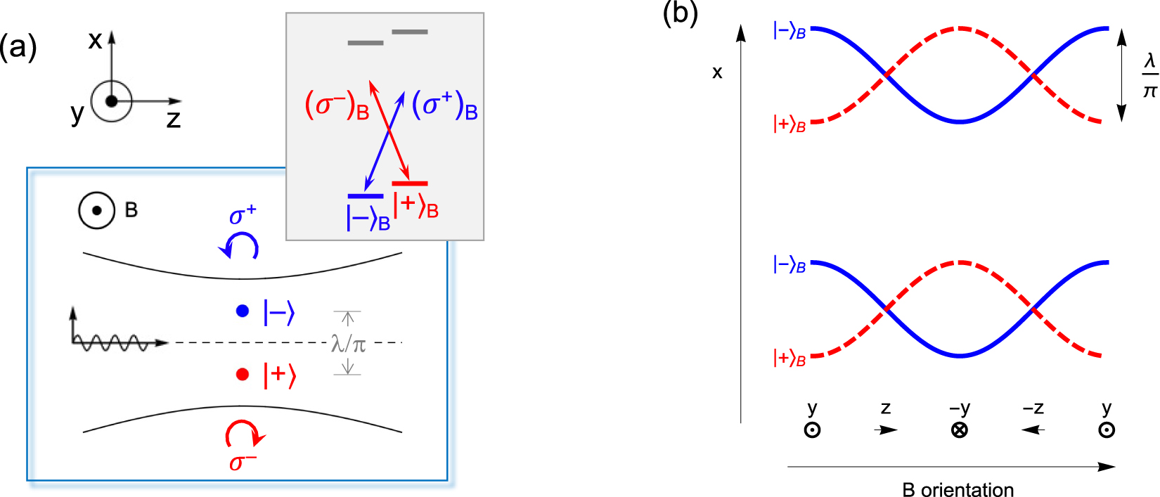
Spin dependent displacement and motion in optical tweezers.
(a) Optical tweezer operating on a j = 1/2 → j′ = 1/2 transition, leading to ±ƛ off-axis displacements for the
It may also be interesting to rotate the field at the resonant frequency ω of the trap, effectively shaking the traps back and forth:
While the discussion in this paper has focused on atoms as the spinning dipole, the effects should not be restricted to atoms. One may ask, for example, whether one could observe them with nanoparticles, much smaller than the wavelength of light. A key requirement would be the preferential scattering of one circular polarization component over the other. The nanoparticles do not have to physically rotate at the optical frequency, only a rotating electric dipole must be induced. One might think about using magnetized particles, lined up in a magnetic field, or dielectric particles with a strong Faraday rotation (Verdet constant), again in a magnetic field.
7 Discussion
While analogies can be tremendously helpful in guiding one’s thoughts, there are always limits. The optical analogy to the Magnus effect is no exception in that it will break if we push it too far. It would be tempting to associate the rotation direction of the dipole with the sign of the deflection angle. In the conventional Magnus effect this is indeed correct: the air stream is deflected in the ball’s spinning direction. In the optical analogy, on the other hand, the beam can be deflected in either direction, depending on the detuning from the atomic resonance, see Eq. (6). The optical case is an interference effect, which is absent in a stream of air particles. Thus, while the optical case requires coherence, the conventional Magnus effect occurs in an inherently dissipative setting. In fact, the ball’s rotation rate will slow down as a result of air viscosity. By contrast, the spinning dipole discussed here is driven by the laser field; it would not spin without it.
Another striking difference is that the air stream in the conventional Magnus effect is usually taken to be uniform (in the absence of the spinning ball), whereas the optical analog vanishes in the plane-wave limit. In this light, it is remarkable that the displacement of the trapping position in an optical tweezer is always ƛ, independent of the size of the waist. Now, if we increase the tweezer waist w0 to an ever greater value, we do eventually end up with a plane wave, although the displacement is an ever smaller fraction of the waist, ƛ/w0 → 0. Finally, in the plane wave limit, the tweezer no longer confines the atom, so that ‘trap displacement’ loses its meaning. What does remain is the apparent position shift of the circular dipole, as can be observed by imaging the atom, even using plane waves. The universality of the ƛ displacement also suggests that it may be interesting to investigate this problem from a topological perspective. Earlier work has also connected previous versions of the optical Magnus effect with Berry phases and the Aharonov–Bohm effect [36, 37, 39].
As a final remark, it would be interesting to generalize the effects for different level schemes. This would include larger values of j, j′, as well as different types of transitions, such as magnetic dipole, electric quadrupole [10], etc. The latter, for example, supports more tightly wound spiral waves
8 Summary
A brief personal, historical account of the days that saw the emergence of OAM has been presented. After that, some new ideas were discussed related to the coupling of transverse SAM and OAM. It is predicted that a circular dipole can deflect a focused laser beam, similar to a spinning ball deflecting a stream of air in the Magnus effect. For an atom trapped in an optical tweezer this may lead to a spin-dependent, off-axis displacement of up to ±ƛ. This displacement is independent of many trap parameters. An external magnetic field can be used to induce spin-dependent motion or to perform Stern–Gerlach type analysis of the spin states of the atom in the tweezer.
Acknowledgments
I would like to thank N. J. van Druten, R. Gerritsma, J. Minar, and A. Urech for stimulating and encouraging discussions. This work was supported by the Netherlands Organization for Scientific Research (NWO).
-
Author contribution: All the authors have accepted responsibility for the entire content of this submitted manuscript and approved submission.
-
Research funding: None declared.
-
Conflict of interest statement: The authors declare no conflicts of interest regarding this article.
References
[1] L. Allen, M. W. Beijersbergen, R. J. C. Spreeuw, and J. P. Woerdman, “Orbital angular momentum of light and the transformation of Laguerre-Gaussian laser modes,” Phys. Rev. A, vol. 45, pp. 8185–8189, 1992. https://doi.org/10.1103/physreva.45.8185.Search in Google Scholar PubMed
[2] J. D. Jackson, Classical Electrodynamics, 3rd ed., New York, NY, Wiley, 1999, Ch. 7, 9, 10.10.1119/1.19136Search in Google Scholar
[3] J. Frederick Nye, M. V. Berry, and F. C. Frank, “Dislocations in wave trains,” Proc. R. Soc. London, Ser. A, vol. 336, no. 1605, pp. 165–190, 1974.10.1098/rspa.1974.0012Search in Google Scholar
[4] P. Coullet, L. Gil, and F. Rocca, “Optical vortices,” Opt. Commun., vol. 73, no. 5, pp. 403–408, 1989. https://doi.org/10.1016/0030-4018(89)90180-6.Search in Google Scholar
[5] M. Babiker, W. L. Power, and L. Allen, “Light-induced torque on moving atoms,” Phys. Rev. Lett., vol. 73, no. 9, pp. 1239–1242, 1994. https://doi.org/10.1103/physrevlett.73.1239.Search in Google Scholar PubMed
[6] L. Allen, M. Babiker, W. K. Lai, and V. E. Lembessis, “Atom dynamics in multiple Laguerre-Gaussian beams,” Phys. Rev. A, vol. 54, no. 5, pp. 4259–4270, 1996. https://doi.org/10.1103/physreva.54.4259.Search in Google Scholar PubMed
[7] W. K. Lai, M. Babiker, and L. Allen, “Radiation forces on a two-level atom in a σ+ - σ- configuration of Laguerre-Gaussian beams,” Opt. Commun., vol. 133, no. 1, pp. 487–494, 1997. https://doi.org/10.1016/s0030-4018(96)00432-4.Search in Google Scholar
[8] J. W. R. Tabosa and D. V. Petrov, “Optical pumping of orbital angular momentum of light in cold cesium atoms,” Phys. Rev. Lett., vol. 83, no. 24, pp. 4967–4970, 1999. https://doi.org/10.1103/physrevlett.83.4967.Search in Google Scholar
[9] M. F. Andersen, C. Ryu, P. Cladé, et al.., “Quantized rotation of atoms from photons with orbital angular momentum,” Phys. Rev. Lett., vol. 97, no. 17, p. 170406, 2006. https://doi.org/10.1103/physrevlett.97.170406.Search in Google Scholar
[10] C. T. Schmiegelow, J. Schulz, H. Kaufmann, T. Ruster, U. G. Poschinger, and F. Schmidt-Kaler, “Transfer of optical orbital angular momentum to a bound electron,” Nat. Commun., vol. 7, no. 1, p. 12998, 2016. https://doi.org/10.1038/ncomms12998.Search in Google Scholar PubMed PubMed Central
[11] H. He, M. E. J. Friese, N. R. Heckenberg, and H. Rubinsztein-Dunlop, “Direct observation of transfer of angular momentum to absorptive particles from a laser beam with a phase singularity,” Phys. Rev. Lett., vol. 75, no. 5, pp. 826–829, 1995. https://doi.org/10.1103/physrevlett.75.826.Search in Google Scholar
[12] D. G. Grier, “A revolution in optical manipulation,” Nature, vol. 424, no. 6950, pp. 810–816, 2003. https://doi.org/10.1038/nature01935.Search in Google Scholar PubMed
[13] N. B. Simpson, K. Dholakia, L. Allen, and M. J. Padgett, “Mechanical equivalence of spin and orbital angular momentum of light: an optical spanner,” Opt. Lett., vol. 22, no. 1, pp. 52–54, 1997. https://doi.org/10.1364/ol.22.000052.Search in Google Scholar PubMed
[14] J. T. Barreiro, T.-C. Wei, and P. G. Kwiat, “Beating the channel capacity limit for linear photonic superdense coding,” Nat. Phys., vol. 4, no. 4, pp. 282–286, 2008. https://doi.org/10.1038/nphys919.Search in Google Scholar
[15] K. Y. Bliokh, M. A. Alonso, E. A. Ostrovskaya, and A. Aiello, “Angular momenta and spin-orbit interaction of nonparaxial light in free space,” Phys. Rev. A, vol. 82, no. 6, 2010, Art no. 063825. https://doi.org/10.1103/physreva.82.063825.Search in Google Scholar
[16] K. Y. Bliokh, E. A. Ostrovskaya, M. A. Alonso, O. G. Rodríguez-Herrera, D. Lara, and C. Dainty, “Spin-to-orbital angular momentum conversion in focusing, scattering, and imaging systems,” Opt. Express, vol. 19, no. 27, pp. 26132–26149, 2011. https://doi.org/10.1364/oe.19.026132.Search in Google Scholar
[17] P. B. Monteiro, A. Paulo, M. Neto, and H. Moysés Nussenzveig, “Angular momentum of focused beams: beyond the paraxial approximation,” Phys. Rev. A, vol. 79, no. 3, 2009, Art no. 033830. https://doi.org/10.1103/physreva.79.033830.Search in Google Scholar
[18] G. Oscar Rodríguez-Herrera, D. Lara, K. Y. Bliokh, E. A. Ostrovskaya, and C. Dainty, “Optical nanoprobing via spin-orbit interaction of light,” Phys. Rev. Lett., vol. 104, no. 25, p. 253601, 2010. https://doi.org/10.1103/physrevlett.104.253601.Search in Google Scholar PubMed
[19] T. A. Nieminen, A. B. Stilgoe, N. R. Heckenberg, and H. Rubinsztein-Dunlop, “Angular momentum of a strongly focused Gaussian beam,” J. Opt. Pure Appl. Opt., vol. 10, no. 11, p. 115005, 2008. https://doi.org/10.1088/1464-4258/10/11/115005.Search in Google Scholar
[20] J. Verbeeck, H. Tian, and P. Schattschneider, “Production and application of electron vortex beams,” Nature, vol. 467, no. 7313, pp. 301–304, 2010. https://doi.org/10.1038/nature09366.Search in Google Scholar PubMed
[21] C. W. Clark, R. Barankov, M. G. Huber, M. Arif, D. G. Cory, and D. A. Pushin, “Controlling neutron orbital angular momentum,” Nature, vol. 525, no. 7570, pp. 504–506, 2015. https://doi.org/10.1038/nature15265.Search in Google Scholar PubMed
[22] J. C. T. Lee, S. J. Alexander, S. D. Kevan, S. Roy, and B. J. McMorran, “Laguerre–Gauss and Hermite–Gauss soft X-ray states generated using diffractive optics,” Nat. Photonics, vol. 13, no. 3, pp. 205–209, 2019. https://doi.org/10.1038/s41566-018-0328-8.Search in Google Scholar
[23] A. Mair, A. Vaziri, G. Weihs, and A. Zeilinger, “Entanglement of the orbital angular momentum states of photons,” Nature, vol. 412, no. 6844, pp. 313–316, 2001. https://doi.org/10.1038/35085529.Search in Google Scholar PubMed
[24] L. Rego, K. M. Dorney, N. J. Brooks, et al.., “Generation of extreme-ultraviolet beams with time-varying orbital angular momentum,” Science, vol. 364, no. 6447, 2019, Art no. eaaw9486. https://doi.org/10.1126/science.aaw9486.Search in Google Scholar PubMed
[25] Y. Shen, X. Wang, Z. Xie, et al.., “Optical vortices 30 years on: OAM manipulation from topological charge to multiple singularities,” Light Sci. Appl., vol. 8, no. 1, pp. 1–29, 2019. https://doi.org/10.1038/s41377-019-0194-2.Search in Google Scholar PubMed PubMed Central
[26] S. M. Barnett, M. Babiker, and M. J. Padgett, “Optical orbital angular momentum,” Philos. Trans. R. Soc., A, vol. 375, no. 2087, 2017, Art no. 20150444+. https://doi.org/10.1098/rsta.2015.0444.Search in Google Scholar PubMed PubMed Central
[27] P. Srinivas, R. Dharmavarapu, Anand Vijayakumar, et al.., “Generation and decomposition of scalar and vector modes carrying orbital angular momentum: a review,” Opt. Eng., vol. 59, no. 4, 2019, Art no. 041205.10.1117/1.OE.59.4.041205Search in Google Scholar
[28] A. Forbes, “Structured light: tailored for purpose,” Opt. Photon. News, vol. 31, no. 6, pp. 24–31, 2020. https://doi.org/10.1364/opn.31.6.000024.Search in Google Scholar
[29] S. Franke-Arnold and N. Radwell, “Light served with a twist,” Opt. Photon. News, vol. 28, no. 6, pp. 28–35, 2017. https://doi.org/10.1364/opn.28.6.000028.Search in Google Scholar
[30] S. Franke-Arnold, “Optical angular momentum and atoms,” Philos. Trans. R. Soc., A, vol. 375, no. 2087, 2017. https://doi.org/10.1098/rsta.2015.0435.Search in Google Scholar PubMed PubMed Central
[31] M. J. Padgett, “Orbital angular momentum 25 years on [Invited],” Opt. Express, vol. 25, no. 10, pp. 11265–11274, 2017. https://doi.org/10.1364/oe.25.011265.Search in Google Scholar PubMed
[32] R. J. C. Spreeuw, “Off-axis dipole forces in optical tweezers by an optical analog of the Magnus effect,” Phys. Rev. Lett., vol. 125, no. 23, p. 233201, 2020. https://doi.org/10.1103/physrevlett.125.233201.Search in Google Scholar
[33] G. Magnus, “Ueber die Abweichung der Geschosse, und: Ueber eine auffallende Erscheinung bei rotirenden Körpern,” Ann. Phys., vol. 164, no. 1, pp. 1–29, 1853. https://doi.org/10.1002/andp.18531640102.Search in Google Scholar
[34] B. Ya Zel’dovich and V. S. Liberman, “Rotation of the plane of a meridional beam in a graded-index waveguide due to the circular nature of the polarization,” Sov. J. Quant. Electron., vol. 20, no. 4, p. 427, 1990.10.1070/QE1990v020n04ABEH005947Search in Google Scholar
[35] A. V. Dooghin, N. D. Kundikova, V. S. Liberman, and B. Ya Zel’dovich, “Optical Magnus effect,” Phys. Rev. A, vol. 45, no. 11, pp. 8204–8208, 1992. https://doi.org/10.1103/physreva.45.8204.Search in Google Scholar PubMed
[36] K. Yu. Bliokh and Yu. P. Bliokh, “Topological spin transport of photons: the optical Magnus effect and Berry phase,” Phys. Lett., vol. 333, no. 3, pp. 181–186, 2004. https://doi.org/10.1016/j.physleta.2004.10.035.Search in Google Scholar
[37] K. Yu, “Bliokh. Geometrical optics of beams with vortices: Berry phase and orbital angular momentum Hall effect,” Phys. Rev. Lett., vol. 97, no. 4, 2006, Art no. 043901.10.1103/PhysRevLett.97.043901Search in Google Scholar PubMed
[38] H. Luo, S. Wen, W. Shu, and D. Fan, “Role of transverse-momentum currents in the optical Magnus effect in free space,” Phys. Rev. A, vol. 81, no. 5, 2010, Art no. 053826. https://doi.org/10.1103/physreva.81.053826.Search in Google Scholar
[39] Y. Gorodetski, S. Nechayev, V. Kleiner, and E. Hasman, “Plasmonic Aharonov-Bohm effect: optical spin as the magnetic flux parameter,” Phys. Rev. B, vol. 82, no. 12, p. 125433, 2010. https://doi.org/10.1103/physrevb.82.125433.Search in Google Scholar
[40] M. Onoda, S. Murakami, and N. Nagaosa, “Hall effect of light,” Phys. Rev. Lett., vol. 93, no. 8, 2004, Art no. 083901. https://doi.org/10.1103/PhysRevLett.93.083901.Search in Google Scholar PubMed
[41] O. Hosten and P. Kwiat, “Observation of the spin Hall effect of light via weak measurements,” Science, vol. 319, no. 5864, pp. 787–790, 2008. https://doi.org/10.1126/science.1152697.Search in Google Scholar PubMed
[42] K. Y. Bliokh, A. Niv, V. Kleiner, and E. Hasman, “Geometrodynamics of spinning light,” Nat. Photonics, vol. 2, no. 12, pp. 748–753, 2008. https://doi.org/10.1038/nphoton.2008.229.Search in Google Scholar
[43] K. P. Wang, J. Zhuang, H. Xiao-Dong, et al.., “High-fidelity manipulation of the quantized motion of a single atom via Stern–Gerlach splitting,” Chin. Phys. Lett., vol. 37, no. 4, 2020, Art no. 044209. https://doi.org/10.1088/0256-307x/37/4/044209.Search in Google Scholar
[44] C. Tamm and C. O. Weiss, “Bistability and optical switching of spatial patterns in a laser,” J. Opt. Soc. Am. B, vol. 7, no. 6, pp. 1034–1038, 1990. https://doi.org/10.1364/josab.7.001034.Search in Google Scholar
[45] Richard A. Beth, “Mechanical detection and measurement of the angular momentum of light,” Phys. Rev., vol. 50, no. 2, pp. 115–125, 1936.10.1887/0750309016/b1142c3Search in Google Scholar
[46] M. Kristensen, M. W. Beijersbergen, and J. P. Woerdman, “Angular momentum and spin-orbit coupling for microwave photons,” Opt. Commun., vol. 104, no. 4, pp. 229–233, 1994. https://doi.org/10.1016/0030-4018(94)90547-9.Search in Google Scholar
[47] S. J. van Enk and G. Nienhuis, “Spin and orbital angular momentum of photons,” Europhys. Lett., vol. 25, no. 7, pp. 497–501, 1994. https://doi.org/10.1209/0295-5075/25/7/004.Search in Google Scholar
[48] S. J. van Enk and G. Nienhuis, “Commutation rules and eigenvalues of spin and orbital angular momentum of radiation fields,” J. Mod. Opt., vol. 41, no. 5, pp. 963–977, 1994. https://doi.org/10.1080/09500349414550911.Search in Google Scholar
[49] J. D. Thompson, T. G. Tiecke, A. S. Zibrov, V. Vuletić, and M. D. Lukin, “Coherence and Raman sideband cooling of a single atom in an optical tweezer,” Phys. Rev. Lett., vol. 110, no. 13, p. 133001, 2013. https://doi.org/10.1103/physrevlett.110.133001.Search in Google Scholar
[50] C. G. Darwin, “Notes on the theory of radiation,” Proc. R. Soc. London, Ser. A, vol. 136, no. 829, pp. 36–52, 1932.10.1098/rspa.1932.0065Search in Google Scholar
[51] G. Araneda, S. Walser, Y. Colombe, et al.., “Wavelength-scale errors in optical localization due to spin–orbit coupling of light,” Nat. Phys., vol. 15, no. 1, pp. 17–21, 2019. https://doi.org/10.1038/s41567-018-0301-y.Search in Google Scholar PubMed PubMed Central
[52] B. Richards and E. Wolf, “Electromagnetic diffraction in optical systems, II. Structure of the image field in an aplanatic system,” Proc. Roy. Soc. Lond. Math. Phys. Sci., vol. 253, no. 1274, pp. 358–379, 1959.10.1098/rspa.1959.0200Search in Google Scholar
[53] J. P. Gordon and A. Ashkin, “Motion of atoms in a radiation trap,” Phys. Rev. A, vol. 21, no. 5, pp. 1606–1617, 1980. https://doi.org/10.1103/physreva.21.1606.Search in Google Scholar
[54] R. Dorn, S. Quabis, and G. Leuchs, “The focus of light—linear polarization breaks the rotational symmetry of the focal spot,” J. Mod. Opt., vol. 50, no. 12, pp. 1917–1926, 2003. https://doi.org/10.1080/0950034031000095812.Search in Google Scholar
[55] L. Caldwell and M. R. Tarbutt, “Sideband cooling of molecules in optical traps,” Phys. Rev. Res., vol. 2, no. 1, 2020, Art no. 013251. https://doi.org/10.1103/physrevresearch.2.013251.Search in Google Scholar
[56] J. Pellegrino, R. Bourgain, S. Jennewein, et al.., “Observation of suppression of light scattering induced by dipole-dipole interactions in a cold-atom ensemble,” Phys. Rev. Lett., vol. 113, p. 133602, 2014. https://doi.org/10.1103/physrevlett.113.133602.Search in Google Scholar
[57] S. Machluf, J. B. Naber, M. L. Soudijn, J. Ruostekoski, and R. J. C. Spreeuw, “Collective suppression of optical hyperfine pumping in dense clouds of atoms in microtraps,” Phys. Rev. A, vol. 100, no. 5, 2019, Art no. 051801. https://doi.org/10.1103/physreva.100.051801.Search in Google Scholar
[58] H. Moritz, T. Stöferle, M. Köhl, and T. Esslinger, “Exciting collective oscillations in a trapped 1D gas,” Phys. Rev. Lett., vol. 91, no. 25, p. 250402, 2003. https://doi.org/10.1103/physrevlett.91.250402.Search in Google Scholar
[59] B. Paredes, A. Widera, V. Murg, et al.., “Tonks–Girardeau gas of ultracold atoms in an optical lattice,” Nature, vol. 429, no. 6989, pp. 277–281, 2004. https://doi.org/10.1038/nature02530.Search in Google Scholar PubMed
[60] T. Kinoshita, T. Wenger, S. David, and Weiss, “Observation of a one-dimensional tonks-Girardeau Gas,” Science, vol. 305, no. 5687, pp. 1125–1128, 2004. https://doi.org/10.1126/science.1100700.Search in Google Scholar PubMed
[61] J. Thibaut, J. Armijo, T. Berrada, K. V. Kheruntsyan, and I. Bouchoule, “Sub-poissonian fluctuations in a 1D Bose gas: from the quantum quasicondensate to the strongly interacting regime,” Phys. Rev. Lett., vol. 106, no. 23, p. 230405, 2011. https://doi.org/10.1103/PhysRevLett.106.230405.Search in Google Scholar PubMed
[62] J. Rui, D. Wei, A. Rubio-Abadal, et al.., “A subradiant optical mirror formed by a single structured atomic layer,” Nature, vol. 583, no. 7816, pp. 369–374, 2020. https://doi.org/10.1038/s41586-020-2463-x.Search in Google Scholar PubMed
[63] R. J. Bettles, S. A. Gardiner, and C. S. Adams, “Enhanced optical cross section via collective coupling of atomic dipoles in a 2D array,” Phys. Rev. Lett., vol. 116, p. 103602, 2016. https://doi.org/10.1103/physrevlett.116.103602.Search in Google Scholar
[64] G. Facchinetti, S. D. Jenkins, and J. Ruostekoski, “Storing light with subradiant correlations in arrays of atoms,” Phys. Rev. Lett., vol. 117, no. 24, p. 243601, 2016. https://doi.org/10.1103/physrevlett.117.243601.Search in Google Scholar PubMed
[65] E. Shahmoon, D. S. Wild, M. D. Lukin, and S. F. Yelin, “Cooperative resonances in light scattering from two-dimensional atomic arrays,” Phys. Rev. Lett., vol. 118, no. 11, p. 113601, 2017. https://doi.org/10.1103/physrevlett.118.113601.Search in Google Scholar PubMed
[66] Simon Stellmer, R. Grimm, and F. Schreck, “Detection and manipulation of nuclear spin states in fermionic strontium,” Phys. Rev. A, vol. 84, 2011, Art no. 043611. https://doi.org/10.1103/physreva.84.043611.Search in Google Scholar
[67] W. Petrich, M. H. Anderson, J. R. Ensher, and E. A. Cornell, “Stable, tightly confining magnetic trap for evaporative cooling of neutral atoms,” Phys. Rev. Lett., vol. 74, no. 17, pp. 3352–3355, 1995. https://doi.org/10.1103/physrevlett.74.3352.Search in Google Scholar PubMed
© 2021 Robert J. C. Spreeuw published by De Gruyter, Berlin/Boston
This work is licensed under the Creative Commons Attribution 4.0 International License.
Articles in the same Issue
- Frontmatter
- Editorial
- Photonic angular momentum: progress and perspectives
- Reviews
- Spiraling light: from donut modes to a Magnus effect analogy
- Orbital angular momentum and beyond in free-space optical communications
- Research Articles
- Parabolic-accelerating vector waves
- Experimental synthesis of partially coherent beam with controllable twist phase and measuring its orbital angular momentum
- Harnessing of inhomogeneously polarized Hermite–Gaussian vector beams to manage the 3D spin angular momentum density distribution
- Introducing Berry phase gradients along the optical path via propagation-dependent polarization transformations
- Angular momentum redirection phase of vector beams in a non-planar geometry
- Transverse shifts and time delays of spatiotemporal vortex pulses reflected and refracted at a planar interface
- Spatiotemporal optical vortices with arbitrary orbital angular momentum orientation by astigmatic mode converters
- Digital toolbox for vector field characterization
- Phase conjugation of twisted Gaussian Schell model beams in stimulated down-conversion
- Spin to orbital angular momentum transfer in frequency up-conversion
- Deep-learning-based recognition of multi-singularity structured light
- Reconfigurable terahertz metasurfaces coherently controlled by wavelength-scale-structured light
- Nonlinear wavefront engineering with metasurface decorated quartz crystal
- Nanostructured silica spin–orbit optics for modal vortex beam shaping
- Spin separation based on-chip optical polarimeter via inverse design
- Photonic integrated chip enabling orbital angular momentum multiplexing for quantum communication
- Fabrication of lithium niobate fork grating by laser-writing-induced selective chemical etching
- High-power thin-disk lasers emitting beams with axially-symmetric polarizations
- The generation of femtosecond optical vortex beams with megawatt powers directly from a fiber based Mamyshev oscillator
- Generation of hexagonal close-packed ring-shaped structures using an optical vortex
- A phase-to-intensity strategy of angular velocity measurement based on photonic orbital angular momentum
- SDM transmission of orbital angular momentum mode channels over a multi-ring-core fibre
- Dynamic aerosol and dynamic air-water interface curvature effects on a 2-Gbit/s free-space optical link using orbital-angular-momentum multiplexing