Repair Welding of the Tunnel Defect in Friction Stir Weld
-
Weipo Li
 ,
Congwei Cai
,
Congwei Cai

Abstract
The tunnel defect formed in friction stir weld would dramatically push the mechanical properties of joints into deterioration. In this study, friction stir welding process was adopted to repair the joints of 7N01 aluminum alloy with tunnel defect. The effects of friction stir repair welding process on the microstructure and mechanical properties were comprehensively investigated. Microstructure of the repaired joints shows that the grain size in nugget zone decreases slightly while the recrystallization in the retreating side of thermo-mechanically affected zone is intensified as the joints are repaired. The microhardness of the repaired joints declined slightly compared with the defective joint. However, the yield strength and tensile strength increase and recover to the values of the joints free of defect. The longitudinal residual stress in weld zone increased remarkably as the repair times increase. Compared with the once repaired joint, yield strength and tensile strength of the twice repaired joint reduced slightly, and the throat thickness also reduced during the repeated repair welding process. Therefore, the times of repair welding applied should be limited actually.
Introduction
As a new developing promising solid state welding process in recent years [1, 2], friction stir welding (FSW) is characterized by the high welding quality, low production cost and low distortion, which can be utilized to weld some materials that are difficult to fusion weld [3, 4]. However, as its ever application in practice, defects caused by improper welding parameters or unsatisfied technological conditions were unwillingly and inevitably appeared during FSW process, which would compromise its effectiveness [5, 6, 7, 8, 9]. So, it is necessary to analyze and repair the defects.
During the FSW process, different locations of materials would undergo distinct thermodynamic histories [10, 11, 12]. For the top of the joint, it tends to be in good quality due to its synchronous experience of stirring and friction. For the middle of the joint, it is stirred by rotation tool and showed the least heat dissipation, which is qualified for mechanical properties. In contrast, the bottom of the joint undergoes the least thermodynamic effect and the most heat dissipation, which easily leads to much more defects, such as the tunnel defect [13, 14].
Once defect occurs during FSW process, the joints would suffer from collapse if lack of repair welding. So, it is necessary to carry out repair welding accordingly. For example, Katsas et al. [15] experimented that the repair welding specimens presented favorable in the bending tests. About the volume defect in FSW welds, Liu et al. [16] considered that the groove defect could be removed by FSW repair welding. Rosen et al. [17] used FSW to repair voids in aluminum alloy and sturdy repaired joint was obtained. But as to the tunnel defect which is more harmful to mechanical properties [18], there is no publications about its repair welding so far. In this study, FSW is elaborately adopted to repair the tunnel defect formed in the bottom of FSW welds. Meanwhile, the microstructures and mechanical properties of both original and repaired joints are comprehensively investigated.
Experiment
Materials
The base metal for utility is a 7N01-T4 aluminum alloy plate with a thickness of 6 mm. And its chemical compositions are listed in Table 1. The plates were cut and machined into rectangular welding samples of 1000 mm in length and 150 mm in width. After cleaned by an angle grinder, the samples were welded and repair-welded using a FSW machine (MTI America). The welding stir-pin was designated as a frustum contour with right-handed threads of 5.8 mm in length.
Chemical composition (wt.%) of a 7N01-T4 aluminum alloy plate.
| w(Zn) | w(Mg) | w(Cu) | w(Cr) | w(Mn) | w(Si) | w(Fe) | w(Al) |
|---|---|---|---|---|---|---|---|
| 4.60 | 1.20 | 0.20 | 0.20 | 0.15 | 0.35 | 0.40 | Bal. |
Welding and repair welding
The original butt-welded joints in longitude with tunnel defect were obtained using the specific technological parameters presented in Table 2. Afterwards, two defective joints were repaired based on the FSW repairing parameters in Table 2. One of the joints underwent FSW repair welding once, meanwhile, the other one underwent repeated repair welding twice. So, three sorts of joints were available to investigate, including the original joint with tunnel defect, the joints repaired once and twice.
Technological parameters of welding for original joints with tunnel defect and repaired joints.
| Sort | Rotationspeed/(r/min) | Weldingspeed/(mm/min) | Constant pressure/(KN) | Press amount/(mm) |
|---|---|---|---|---|
| Original welding | 600 | 400 | 0 | 0.1 |
| Repair welding | 800 | 300 | 9 | 0 |
Analytical tests
All the joints were cut from cross-section (perpendicular to the welding direction) using electrical-discharge cutting machine (DK7725/1-A, China). The metallographic specimens were polished on a disc polishing machine with different grades of emery paper and a polishing compound, and then etched with a color metallographic technique. Zeiss metallurgical microscope (Axiovert. Al, Germany) was adopted to observe the microstructure of nugget zone (NZ) and thermo- mechanically affected zone (TMAZ) of the joints. The testing samples in size of 100×20×6 mm were polished and measured using a Vickers microhardness testing machine (TMVS-1, China) with a load of 500 g, a duration time of 10 s and a distance between the adjacent points of 1 mm. Electronic-tensile tester (Zwick/Roell Z600E, Germany) was used to test the tensile specimens. Scanning electron microscope (Zeiss Ultra 55, Germany) took over for using to observe the fracture morphology. Triplex bending tester (WZW-3000, Germany) was employed to evaluate the bending specimens by face and root bend test. The longitudinal residual stress was measured using ultrasonic method based on the principle that the velocity of longitudinal critically refracted (LCR) wave was changed due to the residual stress [19, 20, 21]. The residual stress in both top and bottom surface with a adjacent measuring points of 5 mm was measured.
Results and discussion
Macro and microstructures of the joints
Typical cross-section of the original joints with tunnel defect and corresponding repaired joints with the retreating side (RS) and the advancing side (AS) are shown in Figure 1. When improper process parameters were employed, the plasticized material failed to refill to the back surface of the joints. Then, a continuously distributing tunnel defect was forming with a diameter of more than 2 mm at the distance of 2 mm from the bottom surface of the joint. After the once repair welding, the tunnel defect tended to disappear. Further one more repair welding was conducted on the joint. The width of the nugget zone turn to increase by 1 mm and 2 mm, compared with the once repaired joint and the original joint respectively. However, the throat thickness of the once repaired joint and the twice repaired joint is decreased by 0.1 mm and 0.4 mm respectively, compared with the original joint.

Macrostructure of the original and repaired joints.
Representative micrographs of defective joint and two repaired joints show the gain structure in the center of nugget zone. The average size of equiaxed grain in nugget zone tends to decrease slightly (Figure 2(a)–(c)) on the increasing times of repair welding. It might be attributed to the effective repair welding, in which the grain in nugget zone was stirred and heated uniformly by the high-speed spinning stir-pin. Also, the microstructure of TMAZ for the three joints are investigated. As shown in Figure 2(d)–(f), recrystallization occurs on the RS after repair welding, compared with the original joint. However, there is no significant change on the AS.

Microstructures of the original and repaired joints: (a) NZ of original joint; (b) NZ of the once repaired joints; (c) NZ of the twice repaired joints; (d) TMAZ of original joint; (e) TMAZ of the once repaired joints; (f) TMAZ of the twice repaired joints.
Microhardness of the joints
Microhardness of the joints was measured according to the condition of schematic diagram shown in Figure 3, in which the selected two lines for determining hardness values at the cross-section were located at a distance of 2 mm from the top and the bottom surfaces respectively. The microhardness profiles of original and two repaired joints are showed in Figure 4. It turn out that microhardness of the once repair joint decrease slightly compared with the original joint. However, microhardness of the twice repaired joint increase slightly compared with the once.

Schematic diagram of hardness measuring.
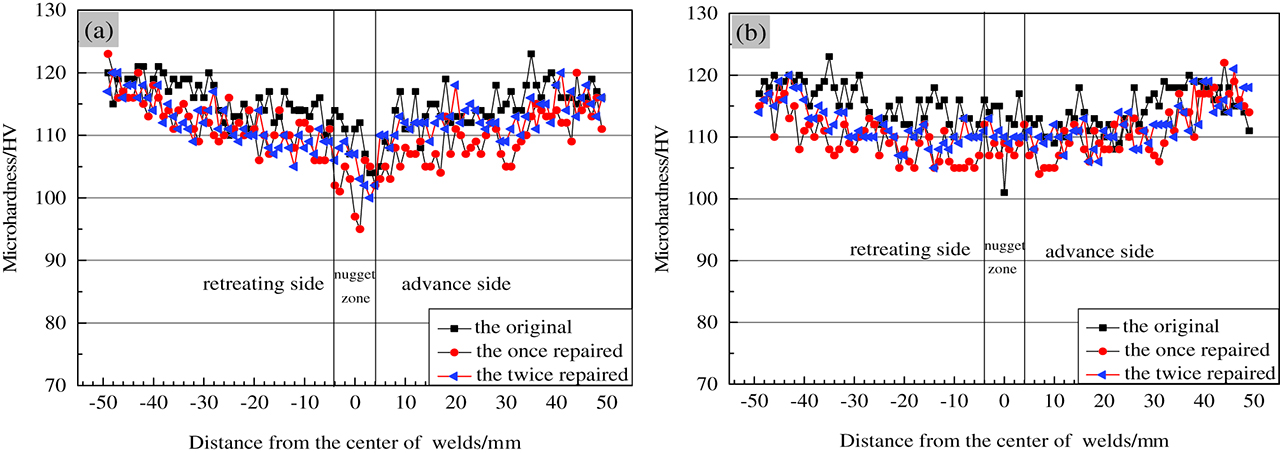
Hardness profiles of original and repaired joints: (a) distanced 2 mm from the top surface; (b) distance 2 mm from the bottom surface.
Generally speaking, microhardness of 7N01 aluminum joints is relevant to the sequence of precipitating phase. For the original joint, the main strengthening phases are GP zones, in which microhardness points at 115 HV. During the once repair welding processes, part of GP zones would dissolve,thus, their microhardness would decrease to 110HV. Meanwhile, microhardness of the twice repaired joint would climb slightly into 112HV because part of strengthening phases reform into metastable phaseη'[22, 23]. However, the grain size (as shown in Figure 2 (c), (f) would decrease after the repair welding, which might contribute to the increase of hardness of the twice repaired joints.
Tensile properties of joints
Tensile testing results of the original joints and two repaired joints are summarized in Table 3. It is surprisingly found that both of the yield strength (Rp0.2) and tensile strength increase on the sequence of repair welding times. For example, in terms of tensile strength, it is only 207.4 MPa of the original joints. After once and twice repaired, the tensile strength of the points raised to 373.8 MPa and 351.5 MPa, increase by 80% and 69% percent, respectively. The same tendency come to yield strength. The yield strength improve to 240.3 MPa and 237.2 MPa, increased by 52% and 50% compared with that of the original joint (158.6 MPa). So, it could be seen that the repair welding is applicable to the joints with tunnel defect.
Results of repair welding tensile test.
| Number | Yield strength | Tensile strength | Elongatio nA/(%) | Location of break |
|---|---|---|---|---|
| Rp0.2/MPa | Rm/MPa | |||
| Defect-1 | 147.6 | 204.5 | 2.0 | nugget zone(middle) |
| Defect-2 | 161.3 | 208.8 | 2.1 | nugget zone(middle) |
| Defect-3 | 166.9 | 209.0 | 1.7 | nugget zone(middle) |
| Average | 158.6 | 207.4 | 1.9 | ––- |
| Once-1 | 243.1 | 373.5 | 11.6 | nugget zone(AS) |
| Once -2 | 246.9 | 372.9 | 12.2 | nugget zone(AS) |
| Once -3 | 230.9 | 375.1 | 12.2 | nugget zone(AS) |
| Average | 240.3 | 373.8 | 12.0 | ––- |
| Twice-1 | 236.9 | 353.8 | 10.8 | nugget zone(AS) |
| Twice -2 | 240.1 | 346.1 | 12.4 | nugget zone(AS) |
| Twice -3 | 234.5 | 354.7 | 11.8 | nugget zone(AS) |
| Average | 237.2 | 351.5 | 11.7 | ––- |
Fracture morphology of the joints
To good understanding of failure patterns, the fracture morphology of joints after tensile test was analyzed by SEM (Figure 5). Seeing SEM photos of the original joint in a macroscopic scale (Figure 5(a)), it is presented in a periodic “spiral” form, which might be determined by the rotating of stir-pin and the flowing of plasticized fluid.

Fracture morphology of the original and repaired tensile samples: (a) (b) the original joint with tunnel defect; (c) the once repaired joint; (d) the twice repaired joint.
At a higher magnification of SEM morphology, the fractographic features of the original and repaired joints are observed and compared (Figure 5(b)–(d)). For the once or twice repaired joints, the fracture morphology shows a mixed mode including intergranular fracture and shear fracture. Especially, the fracture appears to more seriously delamination after repair welding. Comprehensively taking the fracture morphology, metallographic structure, and tensile properties into consideration, more times of repair welding would compromise the microstructure of the joints. So, it is highly important to limit the times of repair welding
Bending properties of the joints
Four specimens with 6 mm in thickness were chosen from once and twice repaired joints for face bending test and root bending test respectively to evaluate the plasticity of joints. The digital photos of specimens which have experimented for bend testing are presented in Figure 6. Figure 6(a)–(b) show that plastic bending is approved in once repaired joints. However, a slight crack extended 16 mm in length appear in root bending test after the twice repair welding (Figure 6(d)) compared with the 20 mm width of samples, which demonstrating that repeated repair welding might weaken the plasticity of the joint.

The specimens for bending test:(a) (b) once repair welding;(c) (d) twice repair welding.
Residual stress of the joints
The longitudinal residual stress of joints was also tested. As shown in Figure 7, the residual stress in the top surface near weld zone raise up into 130 MPa after once repair welding and climbed into 200 MPa after twice repair welding, increase by 117% and 233% respectively compared with the original joint (60 MPa). A similar trend of residual stress comes to the bottom surface of the joints (Figure 7(b)). The fact that the residual stress near weld zone increase remarkably after repair welding, which might be determined by the undergone thermal stir by stir-pin, in which the restraint intensity of joints enhanced. It is further proved that multiple repair welding should be avoided.

Residual stress curve: (a) top surface of joint; (b) bottom surface of joint.
Conclusions
According to the obtained results, the following conclusions can be summarized:
FSW is a suitable method for repair 7N01 aluminum FSW joints with tunnel defect. However, the times of repair welding applied should be limited actually.
During the repair welding processes, the widths of joints increase significantly and the throat thickness reduces gradually. Meanwhile, the grain sizes decline slightly and present recrystallization on the retreating side of TMAZ after the repair welding.
The microhardness of the joints declines slightly after repair welding. Tensile properties of joint increase remarkably after the repair welding, but the tensile properties of twice repaired joint decrease slightly than the once repaired. Meanwhile, the tensile fracture morphology appears to be more seriously in delamination and the plasticity of the joints declines after repair welding.
The longitudinal residual stress near weld zone increases remarkably after repair welding, which appears a more remarkable increase in twice repair welding.
Acknowledgments
This work is supported by the National Natural Science Foundation of China (No. 51205106), the Natural Science Foundation of Hebei Province (No.E2016208077).
References
[1] T. Dursun and C. Soutis, Mater. Des., 56 (2014) 862–871.10.1016/j.matdes.2013.12.002Search in Google Scholar
[2] M.R. Johnsen, Weld. J., 78 (2) ((1999) 35–39.10.2307/20049207Search in Google Scholar
[3] J.D. Joel, Weld. J., 80 (5) (2001) 30–34.10.1159/000047176Search in Google Scholar
[4] N. Oiwa, S. Iwaki, T. Okada, N. Tanaka and K. Namba, Weld. World, 49 (3-4) (2005) 76–82.10.1007/BF03266479Search in Google Scholar
[5] H. Zhang, S.B. Lin, L. Wu, J.C. Feng and S.L. Ma, Mater. Des., 27 (2006) 805–809.10.1016/j.matdes.2005.01.016Search in Google Scholar
[6] S.B. Dunkerton, D.E. Nicholas and P.D. Sketchley. Great Britain Patent Application No. 9125978, 1991.Search in Google Scholar
[7] Y.G. Kim, H. Fujii and T. Tsumura, Mater. Sci. Eng. A, 415 (2006) 250–254.10.1016/j.msea.2005.09.072Search in Google Scholar
[8] N. Guo, Y.L. Fu, Y.Z. Wang, Q. Meng and Y.X. Zhu, Mater. Des., 113 (2017) 273–283.10.1016/j.matdes.2016.10.030Search in Google Scholar
[9] H.J. Liu, Y.Y. Hu, Y.X. Peng, C. Dou and Z.G. Wang, J. Mater. Process. Technol., 238 (2016) 244–254.10.1016/j.jmatprotec.2016.06.029Search in Google Scholar
[10] S.D. Ji, J.W. Xing, Y.M. Yue, Y.N. Ma, L.G. Zhang and S.S. Gao, Materials, 6 (12) (2013) 5870–5877.10.3390/ma6125870Search in Google Scholar PubMed PubMed Central
[11] Y.C. Zhu, G.Q. Chen, Q.L. Chen, G. Zhang and Q.Y. Shi, Mater. Des., 108 (2016) 400–410.10.1016/j.matdes.2016.06.119Search in Google Scholar
[12] L. Wan, Y.X. Huang, Z.L. Lv, S.X. Lv and J.C. Feng, Mater. Des., 55 (2014) 197–203.10.1016/j.matdes.2013.09.073Search in Google Scholar
[13] A. Tongne, C. Desayaud, M. Jahazi and E. Feulvarch, J. Mater. Process. Technol., 239 (2017) 284–296.10.1016/j.jmatprotec.2016.08.030Search in Google Scholar
[14] J.H. Ouyang and R. Kovacevic, J. Mater. Eng. Perform, 11 (1) (2002) 51–63.10.1007/s11665-002-0008-0Search in Google Scholar
[15] S. Katsas, J. Nikolaou and G. Papadimitriou, Mater. Des., 27 (2006) 968–975.10.1016/j.matdes.2005.02.012Search in Google Scholar
[16] H.J. Liu and H.J. Zhang, Trans. Nonferrous Met. Soc. China, 19 (2009) 563–567.10.1016/S1003-6326(08)60313-1Search in Google Scholar
[17] C.D. Rosen, E. Litwinski and M. Juan. Valdez. US Pat., Pat. No.: 5971252.Search in Google Scholar
[18] N.Z. Khan, A.N. Siddiquee, Z.A. Khan and S.K. Shihab, J. Alloy Compd., 648 (2015) 360–367.10.1016/j.jallcom.2015.06.246Search in Google Scholar
[19] Y. Javadi, M. Akhlaghi and M.A. Najafafabadi, Mater. Des., 45 (2013) 628–642.10.1016/j.matdes.2012.09.038Search in Google Scholar
[20] Y.X. Huang, L. Wan, S.X. Lv, J. Zhang and G.S. Fu, Mater. Des., 50 (2013) 810–816.10.1016/j.matdes.2013.03.088Search in Google Scholar
[21] H.J. Aval, Mater. Des., 87 (2015) 405–413.10.1016/j.matdes.2015.08.050Search in Google Scholar
[22] P. Rometsch, Y. Zhang and S. Knight, Trans. Nonferrous Met. Soc. China, 24 (2014) 2003−2017.10.1016/S1003-6326(14)63306-9Search in Google Scholar
[23] B. Li, X.M. Wang, H. Chen, J. Hu, C. Huang and G. Gou, J. Alloy Compd., 678 (2016) 160–166.10.1016/j.jallcom.2016.03.228Search in Google Scholar
© 2018 Walter de Gruyter GmbH, Berlin/Boston
This article is distributed under the terms of the Creative Commons Attribution Non-Commercial License, which permits unrestricted non-commercial use, distribution, and reproduction in any medium, provided the original work is properly cited.
Articles in the same Issue
- Frontmatter
- Research Article
- Effect of Multidirectional Forging and Heat Treatment on Mechanical Properties of In Situ ZrB2p/6061Al Composites
- Short Communication
- Obtaining Ceramic Materials from Hydroxyapatite Using Spark-Plasma Sintering
- Research Articles
- An Investigation of Wear Behaviors of AA7075 Al Hybrid Composites
- Dephosphorization by Double-Slag Process in Converter Steelmaking
- Simulation of Dynamic Recrystallization Behavior under Hot Isothermal Compressions for as-extruded 3Cr20Ni10W2 Heat-Resistant Alloy by Cellular Automaton Model
- Post-weld Heat Treatment and Groove Angles Affect the Mechanical Properties of T92/Super 304H Dissimilar Steel Weld Joints
- Distribution of P2O5 between P-rich Phase and Matrix Phase in P-bearing Steelmaking Slag
- Mass-Transfer Model for Steel, Slag, and Inclusions during Ladle-Furnace Refining
- Repair Welding of the Tunnel Defect in Friction Stir Weld
- The Interface Reaction between Titanium and Iron-Nickel alloys
- Microstructure and Mechanical Properties of Friction Stir Processed A356 Cast Al under Air Cooling and Water Cooling