Influence of Heat Treatment on the Mechanical Properties of Ni Films on 430 Stainless Steel Substrate
-
Yong Pan


Abstract
Effects of heat treatment on the mechanical properties of Ni films on 430 stainless steel substrate were investigated. The Ni films were annealed at heat treatment temperatures ranging from 0 °C to 800 °C for 2 h. The surface morphology, composition, and texture orientation of Ni films were studied by scanning electron microscopy, energy dispersive spectrometry, and X-ray diffraction. The load–indentation depth curves of Ni films before and after heat treatment were measured by using nanoindentation method. In conjunction with finite element modeling and dimensional analysis, the stress–strain relationships of Ni films on 430 stainless steel substrate at different temperatures are successfully obtained by using a power-law hardening model.
Introduction
With the development of metal film preparation technology, the pulse electro-deposition, as a simple, highly active, and low-cost deposition method, had been used to deposit nanocrystalline films [1]. With respect to the deposition of nanocrystalline film, the pulse electrodeposition had been extensively used to improve the hardness, wear, and corrosion resistance of electroplated metal films [1, 2].
Heat treatment was widely used on 304 stainless steel [3], aluminum alloy [4], and nickel films [5] in order to improve their machining properties for eliminating alloy imbalance phase and over saturation [6] as well as reducing surface cracks, and enhancing adhesion strength of film to substrate [7]. Therefore, it is essential to assess the mechanical properties of Ni films on 430 stainless steel substrate at different temperatures, especially their stress–strain relationships. In comparison to traditional methods, nanoindentation is a convenient, nondestructive method, which has been widely used to measure mechanical properties of small samples, such as hardness, Young’s modulus, yield strength, hardening exponent, etc. [8, 9, 10]. The load–indentation depth relationship of an elastic–plastic material was supposed to be a linear combination of elastic and elastic–perfectly plastic response, and then an optimization method was introduced in reverse analysis [11]. In the work of Dao et al. [12], a computational study was undertaken to identify the extent to which the elastoplastic properties of ductile materials could be determined by instrumented sharp indentation and to quantify their sensitivity to variations of indentation data. They concluded that the unique properties can be obtained by a sharp indentation curve. We also proposed an inverse method for extracting the elastic–plastic properties of metallic thin films from instrumented sharp indentation in terms of dimensional analysis and finite element modeling [13, 14]. A wide range of materials with different elastic modulus, yield strength, and strain-hardening exponent were examined.
In this paper, the surface morphology, composition, and texture orientation of Ni films on 430 stainless steel substrate at different temperatures were studied by scanning electron microscopy (SEM), energy dispersive spectrometry (EDS) and X-ray diffraction (XRD). The load–indentation depth curves of Ni coatings before and after heat treatment were measured using nanoindentation method. In conjunction with finite element modeling and dimensional analysis, we aim to characterize the stress–strain relationships of Ni films on 430 stainless steel substrate at different temperatures by using a power-law hardening model.
Experimental
Samples and heat treatment
A 0.3-mm thick 430 stainless steel sheet was used as the substrate. A uniform nickel film of 3,000 nm thick was prepared by electrodeposition on both sides of the steel sheet. The film was obtained with nickel sulfate electrolyte, which was composed of 250 g of NiSO4·6H2O, 50 g of NiCl2·6H2O and 35 g of H3BO3 per liter. Pure nickel was used as the anode. The pH value was adjusted with sulfuric acid to 4.0 at 42 °C. A conventional rotating disc electrode was used for electrodeposition. Before electroplating, pretreatments were necessary to get rid of the impurities. Then the samples were heated for 2 h at the temperature of 400, 500, 600, 700, and 800 °C in argon protective atmosphere with a purity of 99.9 %. Then the samples were cooled down in the protect atmosphere until room temperature.
The morphology of Ni films on 430 stainless steel substrate at different temperatures was observed by SEM (JMS-5600LV SEM). The chemical composition was studied by the EDS (QUANTA200). The Rigaku D/MAX-2500 X-ray diffusion detector (XRD) was used to calculate the average grain sizes and the texture density of the samples.
Nanoindentation
Nanoindentation tests were conducted by using a Tribo Indenter (Hysitron Inc.) with a three-sided pyramidal Berkovich diamond indenter. Its load and displacement resolutions are 100 nN and 0.1 nm, respectively. Ni films were tested by the maximum load F=1,000 μN with the loading and unloading rate dP/dt=200 μN/s and the holding time T=5 s. In all cases, at least five tests were repeated at a given load to obtain load–indentation depth curves.
Theoretical framework
Material model
For elastic–plastic material, its load–displacement curve is illustrated in Figure 1(a). To improve the accuracy and comparability of hardness and modulus results from nanoindentation experiments, an evaluation of the creep behavior is required. Creep depends on the material and normally diminishes to very low values within some seconds. Nevertheless, it influences the maximum depth and the upper part of the unloading curve in a way that measurement errors of more than 20 % may occur [15]. Hold periods are proposed in dependence on the material type that should be kept for high accuracy measurements. Feng and Ngan solved the problem of indentation on a linear viscoelastic half-space using the correspondence principle between elasticity and linear viscoelasticity [16]. The correction term due to creep in the apparent contact compliance is found to be equal to the ratio of the indenter displacement rate at the end of the load hold to the unloading rate. According to Kick’s law [17], a natural outcome during loading with a Berkovich indenter can be represented as
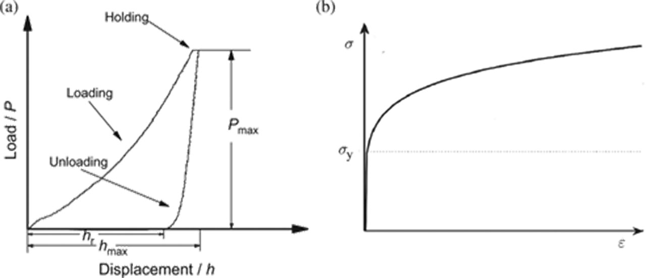
(a) Schematic representation of a load–displacement curve in indentation and (b) the power-law elastic-plastic stress–strain behavior.
where P is the indentation load, h is the indentation depth, and the loading curvature C is a material constant.
As shown in Figure 1(b), for the plastic deformation of metals, a power-law work-hardening law is a fairly good approximation and its corresponding stress–strain curve under uniaxial tension is given by
It is obvious that there are three parameters, i. e. elastic modulus E, initial yield strength σy, and work hardening exponent n. σy is the initial yield stress at zero offset strain [18]. Thus, the three parameters (i. e., E, n, and σy) are essential to determine the stress–strain curve.
Dimensional analysis
Let us consider an ideal situation of a rigid indenter acting on a smooth surface. Here, the force (F) on the indenter and the contact depth (hc) are chosen as dependent variables, and thus, the indentation depth h is an independent variable. Other independent parameters include the indenter half-angle θ and the friction coefficient µ between the indenter and material [19]. The two dependent variables can be written as
where E and v are the elastic modulus and Poisson’s ratio of the material (indenter), respectively. Taking the small deformation of a diamond indenter into account, Ei, vi, and µ can be ignored in eq. (3). As is well known, Poisson’s ratio of metal materials is about 0.3 [20, 21]. Thus, for a given indenter with the angle θ, eq. (3) can be simplified as
Now, we choose E and h as basic physical quantities, and then we have
According to the Π-theorem of dimensional analysis, two nondimensional functions can be obtained as
Elastic modulus
Next, the effective elastic modulus Er and the unloading stiffness S (the slope of the unloading curve in Figure 1(a) are defined as
Hence,
where the projected contact area A of impression can be derived by an empirical shape function at the contact depth hc [22] for conical, cylindrical, spherical, and flat indenters [23]. Furthermore, eqs. (7) and (8) can be rewritten as
Then,
where β is equal to 1.14 and 1.058 for Berkovich and conical indenters, respectively [24]. Once the equivalent elastic modulus is determined by [25]
The elastic modulus E (neglecting deformation of diamond indenter) can be obtained as
Positive and reverse analyses
As illustrated in Figure 2, there are two steps in either the positive analysis or the reverse analysis [25]. During the positive analysis, finite element calculations are first carried out to obtain several groups of load–displacement curves (defined by F, h, S, and hc) for given material combinations (defined by E, σy, and n). Then, dimensionless functions (Пα and Пβ) are determined through numerical fitting to discrete points with proper functions. During the reverse analysis, the load–displacement curve is obtained by nanoindentation tests. Then, Пα and Пβ can be calculated by indentation information (i.e. F, h, and hc). Following the positive and revise analyses [13], σy and n can be extracted from the dimensionless functions in
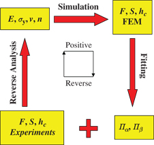
Flowchart for extracting the plastic properties of materials from the sharp indentation–loading curve by using positive and reverse analyses.
Because of the scale effect and the bonding strength, it is very difficult to obtain the mechanical properties of thin films directly. Here, we present the reverse analyses method to characterize the stress–strain relationships of Ni films by nanoindentation.
Results and discussion
Figure 3 shows SEM images and EDS analyses of Ni films on 430 stainless steel substrate at different heat treatment temperatures, where the inset is the corresponding SEM images of cross section. For the as-deposited Ni films, a very smooth surface can be obtained with a grain size of 40 nm in Figure 3(a). In the inset, it is clear that the thickness of Ni film is about 3,000 nm. With the increase of heat treatment temperature, the grain becomes bigger, as shown in Figure 3(b) and (c). The grain size increases to ~1 μm for the heat treatment temperature of 800 °C. The EDS analysis of the cross section at 600 °C indicates that the Ni film/Fe substrate system is mainly composed of Ni and Fe species, as shown in Figure 3(d). It is clearly seen that the content of iron is less than Ni in the film though some iron atoms have diffused into the Ni film. Diffusion interface moved because the elements in the film and substrate diffuse to each other during heat treatment, and the interface moves toward the Ni film with a higher diffusion rate, which matches well with the Kirkendall effect [26].

SEM image of Ni films on 430 stainless steel substrate at different heat treatment temperatures: (a) As-deposited, (b) 500 °C, (c) 700 °C, and (d) EDS of section pattern for Fe and Ni elements at 600 °C.
Texture directions of Ni films on 430 stainless steel substrate at different heat treatment temperatures ranging from 0 °C to 800 °C are examined by XRD in Figure 4. It is found that the structures of the Ni films exhibit a preference of the (1 1 1) and (2 0 0) orientations. With increasing the heat treatment temperatures, the texture directions change slightly, which indicates that no second phase appears. However, the diffraction peaks shift left gradually with increasing heat treatment temperature, implying the formation of new solid solutions.
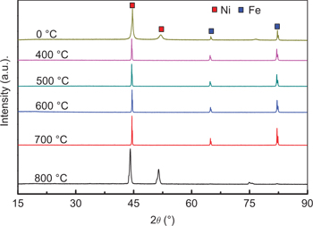
XRD patterns of Ni films on 430 stainless steel substrate at different heat treatment temperatures.
Figure 5 shows the load–displacement curves with the maximum load of 1,000 μN for the Ni films at different heat treatment temperatures ranging from 0 °C to 800 °C. It is found that for a given value of 1,000 μN, the maximum penetration depth increases from 60 nm to 110 nm with increasing heat treatment temperatures from0 °C to 800 °C. This indicates a softening effect of Ni films due to the heat treatment process. The indentation creep displacement is about 5 nm, which agrees well with previous results [27, 28, 29]. For consistency, only load–displacement profiles that mapped onto the same master curve were admitted as valid measurements (the invalid profiles have a fraction less than 5 % for each film we tested).
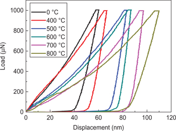
The load–indentation depth curves of Ni films on 430 stainless steel substrate at different heat treatment temperatures.
The influence of the heat treatment temperatures on the measured elastic modulus and hardness values for Ni films is shown in Figure 6(a) and (b), respectively. Both, the elastic modulus and hardness show a strong heat treatment temperature effect with the apparent elastic modulus and hardness decreasing with increasing heat treatment temperatures. For low heat treatment temperatures, the elastic modules are about 160 GPa which is insignificant to the temperatures. However, the heat treatment temperature increases to 800 °C, the elastic modulus value decreases to 70 GPa suddenly, as shown in Figure 6(a). In addition, the hardness value decreases from 7.5 GPa to 3 GPa with the increasing heat treatment temperatures from 0 °C to 800 °C in Figure 6(b). This can be attributed to the increasing grain size due to heat treatment. The smaller the grain size, the stronger the strength, which agrees well with Hall–Petch effect [30]. Furthermore, according to the investigations by Buchheit et al. [31], the evolution of microstructure in the annealed Ni materials corresponded with a dramatic drop in their strength and determined the limiting diffusion-bonding temperature. Significant strength decreases occurred during heat treatments at temperatures greater than 400 °C, corresponding to recrystallization and rapid grain growth of the recrystallized microstructure.
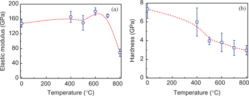
Temperature dependence of (a) elastic modulus and (b) hardness.
According to the reverse analysis, the mechanical properties (E, σy, and n) can be derived from the measured load–displacement curves and their corresponding data (see Table 1). Then, the stress–strain curves are described at different heat treatment temperatures ranging from 0 °C to 800 °C. As shown in Figure 7, the yield strength and elastic modulus decrease with the increase of heat treatment temperature. From Table 1, it can be seen that the elastic modulus decreases from 148 GPa (0 °C) to 69 GPa (800 °C). There is a similar tendency for the decrease of yield strength with the increase of heat treatment temperature. In the case of 0 °C, yield strength is 1.79 GPa. With the increase of heat treatment temperature to 800 °C, yield strength gradually decreases to ~400 MPa. In addition, it is worth noting that, as shown in Table 1, there is a slight change of the n values around 0.4 with the increase of heat treatment temperature.
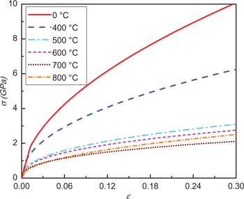
The stress–strain relationships of Ni films on 430 stainless steel substrate at different temperatures.
Mechanical properties of Ni films at different heat treatment temperatures.
| Heat treatment temperature (°C) | E (GPa) | σy (GPa) | n |
|---|---|---|---|
| 0 | 147.95 | 1.79 | 0.538 |
| 400 | 165.86 | 1.01 | 0.469 |
| 500 | 149.71 | 0.47 | 0.414 |
| 600 | 180.46 | 0.41 | 0.392 |
| 700 | 168.84 | 0.31 | 0.379 |
| 800 | 68.94 | 0.40 | 0.465 |
Conclusion
In this paper, the Ni films on 430 stainless steel substrate systems are prepared by pulse electrodeposition at different heat treated temperatures ranging from 0 °C to 800 °C. Using a combination of dimensional analysis and finite element modeling, we extracted successfully the elastic–plastic properties of Ni films at different heat treatment temperatures by an inverse method. The results shown that, with the increase of heat treatment temperatures, the elastic modulus and yield strength obviously decrease. It is expected that this study can be used in the characterization of mechanical properties for metallic films at the heat treatment processes.
Funding statement: This work was supported by the National Natural Science Foundation of China (Grant No. 11372267), and the National High Technology Research and Development Program of China (863 Program) (Grant No. 2013AA032502).
References
[1] N. Qu, D. Zhu, K. Chan and W. Lei, Surf. Coat. Technol., 168 (2003) 123–128.10.1016/S0257-8972(03)00014-8Search in Google Scholar
[2] T. Xu and W. Lee, J. Mater. Process. Technol., 69 (1997) 90–94.10.1016/S0924-0136(96)00099-4Search in Google Scholar
[3] H. Ataee-Esfahani, M. Vaezi, L. Nikzad, B. Yazdani and S. Sadrnezhaad, J. Alloys Compd., 484 (2009) 540–544.10.1016/j.jallcom.2009.04.146Search in Google Scholar
[4] R. Mahmudi, J. Mater. Process. Technol., 82 (1998) 46–52.10.1016/S0924-0136(98)00017-XSearch in Google Scholar
[5] Y. Yin, R.M. Rioux, C.K. Erdonmez, S. Hughes, G.A. Somorjai and A.P. Alivisatos, Science, 304 (2004) 711–714.10.1126/science.1096566Search in Google Scholar
[6] S. Wang, Thin Solid Films, 515 (2007) 8419–8423.10.1016/j.tsf.2007.05.066Search in Google Scholar
[7] J. Lee, D. Ko, K. Lee and B. Kim, J. Mater. Process. Technol., 187 (2007) 309–313.10.1016/j.jmatprotec.2006.11.130Search in Google Scholar
[8] Y. Liu, B. Wang, M. Yoshino, S. Roy, H. Lu and R. Komanduri, J. Mech. Phys. Solids, 53 (2005) 2718–2741.10.1016/j.jmps.2005.07.003Search in Google Scholar
[9] A. Elmustafa and D. Stone, J. Mech. Phys. Solids, 51 (2003) 357–381.10.1016/S0022-5096(02)00033-9Search in Google Scholar
[10] S. Qu, Y. Huang, G. Pharr and K. Hwang, Int. J. Plast., 22 (2006) 1265–1286.10.1016/j.ijplas.2005.07.008Search in Google Scholar
[11] Y.T. Cheng and C.M. Cheng, J. Mater. Res., 14 (1999) 3493–3496.10.1557/JMR.1999.0472Search in Google Scholar
[12] M. Dao, N. Chollacoop, K.J. Van Vliet, T.A. Venkatesh and S. Suresh, Acta Mater., 49 (2001) 3899–3918.10.1016/S1359-6454(01)00295-6Search in Google Scholar
[13] Z.S. Ma, Y.C. Zhou, S.G. Long and C.S. Lu, J. Mater. Sci. Technol., 28 (2012) 626–635.10.1016/S1005-0302(12)60108-XSearch in Google Scholar
[14] Z. Ma, Y. Zhou, S. Long, X. Zhong and C. Lu, Mech. Mater., 54 (2012) 113–123.10.1016/j.mechmat.2012.07.006Search in Google Scholar
[15] T. Chudoba and F. Richter, Surf. Coat. Technol., 148 (2001) 191–198.10.1016/S0257-8972(01)01340-8Search in Google Scholar
[16] G. Feng and A.H.W. Ngan, J. Mater. Res., 17 (2002) 660–668.10.1557/JMR.2002.0094Search in Google Scholar
[17] J.L. Bucaille, S. Stauss, E. Felder and J. Michler, Acta Mater., 51 (2003) 1663–1678.10.1016/S1359-6454(02)00568-2Search in Google Scholar
[18] Z. Ma, Y. Zhou, S. Long and C. Lu, Int. J. Plast., 34 (2012) 1–11.10.1016/j.ijplas.2012.01.001Search in Google Scholar
[19] Z. Ma, Y. Zhou, S. Long and C. Lu, Surf. Coat. Technol., 207 (2012) 305–309.10.1016/j.surfcoat.2012.07.002Search in Google Scholar
[20] K. Tunvisut, N.P. O’Dowd and E.P. Busso, Int. J. Solids Struct., 38 (2001) 335–351.10.1016/S0020-7683(00)00017-2Search in Google Scholar
[21] J. Luo and J. Lin, Int. J. Solids Struct., 44 (2007) 5803–5817.10.1016/j.ijsolstr.2007.01.029Search in Google Scholar
[22] X. Deng, N. Chawla, K. Chawla and M. Koopman, Acta Mater., 52 (2004) 4291–4303.10.1016/j.actamat.2004.05.046Search in Google Scholar
[23] W.C. Oliver and G.M. Pharr, J. Mater. Res., 7 (1992) 1564–1583.10.1557/JMR.1992.1564Search in Google Scholar
[24] P.L. Larsson, A. Giannakopoulos, E. Söderlund, D. Rowcliffe and R. Vestergaard, Int. J. Solids Struct., 33 (1996) 221–248.10.1016/0020-7683(95)00033-7Search in Google Scholar
[25] D. Joslin and W. Oliver, J. Mater. Res., 5 (1990) 123–126.10.1557/JMR.1990.0123Search in Google Scholar
[26] E. Kirkendall and A. Smigelskas, Trans. AIME, 171 (1947) 130–142.Search in Google Scholar
[27] Z.S. Ma, S.G. Long, Y.C. Zhou and Y. Pan, Scripta Mater., 59 (2008) 195–198.10.1016/j.scriptamat.2008.03.014Search in Google Scholar
[28] Z. Ma, S. Long, Y. Pan and Y. Zhou, J. Mater. Sci. Technol., 25 (2009) 90–94.Search in Google Scholar
[29] Z. Ma, S. Long, Y. Pan and Y. Zhou, J. Mater. Sci., 43 (2008) 5952–5955.10.1007/s10853-008-2838-0Search in Google Scholar
[30] Y. Cao, S. Allameh, D. Nankivil, S. Sethiaraj, T. Otiti and W. Soboyejo, Mater. Sci. Eng. A, 427 (2006) 232–240.10.1016/j.msea.2006.04.080Search in Google Scholar
[31] T.E. Buchheit, J.R. Michael, T.R. Christenson, D.A. LaVan and S.D. Leith, Metall. Mater. Trans. A, 33 (2002) 539–554.10.1007/s11661-002-0116-3Search in Google Scholar
© 2017 Walter de Gruyter GmbH, Berlin/Boston
This article is distributed under the terms of the Creative Commons Attribution Non-Commercial License, which permits unrestricted non-commercial use, distribution, and reproduction in any medium, provided the original work is properly cited.
Articles in the same Issue
- Frontmatter
- Research Articles
- High Temperature Mechanical Behavior of MgAl2O4-YAG Eutectic Ceramic In Situ Composites by Float Zone Method
- Phase Transition and Thermal Expansion of Ba3RB3O9 (R = Sm–Yb, and Y)
- Microstructure and Mechanical Properties of Heat-treated T92 Martensitic Heat Resistant Steel
- Short Communication
- Change in Microwave-Absorbing Characteristics during the Oxidation Processes of an Ilmenite Concentrate
- Research Articles
- FeAl2O4 Nanopowders; Structural Analysis and Band Gap Energy
- The Influence of Dwell Time on Low Cycle Fatigue Behavior of Ni-base Superalloy IC10
- Microwave-Assisted Preparation of Activated Carbon from Eupatorium Adenophorum: Effects of Preparation Parameters
- Kinetics of Evaporation of Alloying Elements under Vacuum: Application to Ti alloys in Electron Beam Melting
- Effect of Heat Treatment Technique on the Low Temperature Impact Toughness of Steel EQ70 for Offshore Structure
- Effect of B2O3 on Volume Stability and Strength of Corundum-based Castables
- Thermodynamic Analysis of the Selective Reduction of a Nickeliferous Limonitic Laterite Ore by Hydrogen
- The Analysis of Parametric Sensitivity Based on Designing and Optimization of a New Microwave Heating System
- Influence of Heat Treatment on the Mechanical Properties of Ni Films on 430 Stainless Steel Substrate