An environmental procedure to extract titanium components and metallic iron from Ti-bearing blast furnace slag
-
Wu Zhang
Wu Zhang obtained his PhD from the School of Materials and Metallurgy, Northeastern University, China in 2013. Currently, he serves as an Associate Professor at the School of Materials Science and Engineering, Shenyang Ligong University, China. He is engaged in dealing with industrial solid waste and extracting valuable components in Ti-bearing blast furnace slag.
Li Zhang is an Associate Professor at the School of Materials and Metallurgy, Northeastern University, China. Between 2004 and 2005, he served as a postdoctor fellow in the Korean Academy of Sciences. He is known for his work on comprehensive utilization of Ti-bearing blast furnace slag.
 ,
Yuhai Li
,
Yuhai Li
Yuhai Li is a Professor at the School of Materials Science and Engineering, Shenyang Ligong University, China. He worked as a postdoctor fellow at the Institute of Metal Research, Academia Sinica. He is a member of Shenyang Human Materials and Heat Treatment Association. He has done a lot of work in making comprehensive utilization of Ti-bearing blast furnace slag from 2011 to date.
Xin Li obtained her PhD from the School of Chemical Engineering, Dalian University of Technology, China. Currently, she is an Associate Professor at School of Materials Science and Engineering, Shenyang Ligong University, China. She is engaged in extracting valuable components in industrial solid waste.

Abstract
An environmental procedure to extract titanium components and metallic iron from Ti-bearing blast furnace slag is accomplished via three steps, which are high-temperature modification, gravity separation and hydrometallurgy method. The behaviors of metallic iron during the high-temperature modification process are studied. The feasibility of separating rutile from the matrix phase are investigated; based on the feasibility analysis results, the gravity separation experiment is carried out in order to improve the TiO2 content in the slag. The leaching behaviors and kinetics of non-titanium components in the concentrate of gravity separation are investigated. The activation energy of the leaching process is 62.868 kJ/mol, and circulatory leaching and preparation of synthetic rutile experiments are implemented. Finally, an environmental technological route is proposed for comprehensive utilization of Ti-bearing blast furnace slag.
1 Introduction
Global concern about environmental problems is increasing, such as solid waste pollution and air pollution. High-volume waste materials resulting from large-scale industrial productions have long been considered to be a burden, due to the high costs of their associated post-treatment, storage and disposal [1–3]. The environment-friendly technology for the disposal of industrial wastes has attracted much attention. Typically, the efficient utilization of blast furnace slag is of great significance to the clean production smelting process and the global environment; it can not only provide an outlet for the wastes but can also reduce environmental pollution.
Ti-bearing blast furnace slag is a typical refractory industrial solid waste; it is generated during the blast furnace smelting process of vanadium and titanium magnetite. There are about 25% TiO2 and more than 5% metallic iron in the slag due to the particularity of ferrous minerals used during the melting process. A lot of slag accumulates every year, polluting not only the environment but also waste resources. An environmental technology to extract the titanium components and metallic iron from the slag is necessary. Many methods are applied to extract the titanium from Ti-bearing blast furnace slag, such as acid leaching, fused salt chlorination, high-temperature modification (HTM), preparing alloy process, etc. [4–8]. However, the slag has not been utilized effectively until now due to the various problems, such as water pollution and air pollution.
Based on the previous studies, the extracting process in this work involves three steps: the first step is adjusting the chemical composition of the slag in order to transform the titanium component into the rutile phase; the second step is creating appropriate physical and chemical conditions to make the rutile crystals grown up. The above two steps could be called HTM process. The last step is separating the rutile and iron from the cooled slag by gravity separation and hydrometallurgy method. Compared with other methods to extract titanium from the slag, the HTM process can proceed without being heated during the actual industrial production process; thus, it does not require additional energy. The energy that is required during the HTM process could be provided by high-temperature slag that is discharged from the furnace. Moreover, the experimental results of the HTM process showed that metallic iron would settle down to the bottom of the crucible, and thus the metallic iron can be separated easily after the HTM process. The rutile crystals are separated from the slag by gravity separation and hydrometallurgy methods; the water used in the extracting process is recycled by circulatory process. No emission of waste water and pollution are expected during the production process in this work.
2 Materials and methods
2.1 Materials
The slag used in this work is obtained from the Panzhihua Iron and Steel Company, and the chemical composition is listed in Table 1.
Chemical composition of raw Ti-bearing blast furnace slag (mass fraction, %).
| CaO | MgO | TiO2 | Al2O3 | SiO2 | Fe2O3 | Others |
|---|---|---|---|---|---|---|
| 27.07 | 8.04 | 21.36 | 14.13 | 25.20 | 3.4 | 0.8 |
As shown in Table 1, the raw slag mainly consists of TiO2, CaO, SiO2, Al2O3 and MgO, and other oxides such as Fe2O3, which are inevitably included in the slag, account for the remaining small proportion.
Prior to the heating experiment, the raw slag is ground and screened by a 74-μm mesh to facilitate melting. Analytical grade oxides are mixed with the slag in order to make the titanium components transform into rutile phase. All commercially available chemical agents for experiments are without further purification. All the reagents used in this work were produced by Shenyang reagents factory in Liaoning province, China.
2.2 Experimental procedure
2.2.1 High-temperature modification and samples analysis process:
The experiments of HTM process are carried out in a vertical furnace and the temperature controller is Shimaden FP93 (the temperature measurement accuracy is ±3 K). The working thermocouple is B type and calibrated against a standard thermocouple.
The modified slag samples are analyzed by X-ray diffraction [XRD, using a Philip X pert machine (PANalytical company, Almelo, Holland) with Cu Kα radiation]. Phases in the XRD patterns are analyzed by X pert high score plus software (PANalytical company, Almelo, Holland) equipped with JCPDS PDF 4 database.
A patch of modified slag is chipped and polished on a buffing machine, and then metallographic microscope (201A-D, Shanghai optical instrument factory, Shanghai, China) and scanning electron microscope with the model of 201A-D and SSX-550 (Shanghai optical instrument factory, Shanghai, China) are used to observe the micro-morphology of the modified slag.
Scanning electron microscopy combined with energy-dispersive X-ray (SEM-EDX, Shimadzu Corporation, Kyoto, Japan) analysis enabled the characterization of phases that are present in small concentration and may not be analyzed by XRD analysis. The slags are therefore fully characterized by scanning severa1 areas during SEM-EDX analysis.
Titanium enrichment ratio is a primary indicator for HTM process. We use the volume fraction of rutile in the modified slag to measure the titanium enrichment degree; the overall uncertainties are ±0.3%. We convert the crystal size of rutile into equivalent circle to describe the size of rutile crystals, and the overall uncertainty is ±0.7%. Line intercept method is applied to determine the average grain size and volume fraction of rutile crystals; the sample homogeneity, magnification and numbers of measured fields are readily sources of error during the measurement.
2.2.2 Titanium component separation process:
The titanium component separation process proceeds via two stages in this work; the first is gravity separation process, and the second is leaching of non-titanium components. The equipment of gravity separation process is shaking table (model: 6-s, Hubei Mining Machinery Factory, Hubei province, China), the vibration frequency and the shaking stroke are 360 per minute and 12 mm, respectively.
The materials used in leaching process are gravity separation concentrates. Leaching experiments are carried out in a 1000-ml-capacity glass reactor fitted with multisockets, with the sockets being fitted with quick-fit glass adaptors and a condenser to prevent evaporation losses. The reactor is heated in a water bath with provision to control the bath temperature to maintain the reactor temperature within ±1 K. The leaching processes consist of two steps: (1) alkali leaching, process in which silicon and aluminum components could be removed; and (2) diluted hydrochloric acid (0.88% wt) leaching, process in which magnesium and iron components could be removed.
3 Results and discussion
3.1 Phase transaction of titanium before and after high-temperature modification process
Figure 1 shows the SEM images for the raw slag and modified slag. As shown in Figure 1, combining with the previous work [5, 7–9], there are five phases in the raw slag, which are perovskite, Ti-rich diopside, titanaugite, spinel and metallic iron, while there are only two phases in the modified slag; one is rutile phase, and the other is called matrix phase in this work. Table 2 shows the energy dispersive spectrometer (EDS) analysis results of the modified slag.
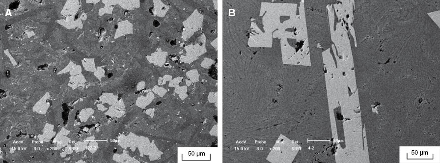
Back scattering microscopic morphology of the modified slag: (A) before modification; and (B) after modification.
EDS results of Figure 1B.
| Area | Element | Weight % |
|---|---|---|
| White | O | 34.862 |
| Ti | 65.138 | |
| Gray | O | 44.469 |
| Mg | 2.759 | |
| Al | 8.061 | |
| Si | 24.795 | |
| Ca | 15.277 | |
| Ti | 1.168 | |
| Fe | 3.471 |
As shown in Figure 1 and Table 2, most of the titanium components in the slag are enriched in the rutile phase. Moreover, the grain size of the titanium-containing phase had grown obviously, which is quite conducive to the separation process.
3.2 The behavior of metallic iron in high-temperature modification process
During the vanadium-titanium magnetite blast furnace smelting process, metal droplets are brought into the slag due to high viscosity of the liquid slag; this part of metal droplets is wrapped in the slag, and it is one of the most serious causes of metal loss [4]. In addition, the loss of metallic iron during the vanadium-titanium magnetite blast furnace smelting process is much more than that during ordinary blast furnace smelting process due to the special properties of the slag; thus, it is necessary to recover the metallic iron in the slag. During the experiments, we found that most of the metallic iron in the slag moved to the bottom of the container under the effect of gravity; this makes it easy for the metallic iron to be recovered. Figure 2 is a photo of the modified slag and metallic iron.
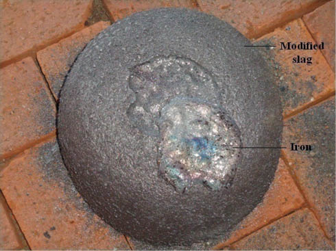
Photo of modified slag and iron.
The density of liquid iron is greater than slag; thus, the iron would settle down to the bottom of the melt. The movement of iron in the liquid slag is similar to gas bubbles moving in the liquid; the settling velocity of iron can be calculated by Stokes theorem [10]:
where V is the average settling velocity of iron (m/s); r1 is the average radius of liquid iron droplets (m); g is gravity acceleration (m/s2); ρ1 and ρ2 are the density of iron and molten slag (kg/m3); and η2 is the average viscosity of molten slag (pa s). According to the references [5, 7, 8], when the temperature is 1733 K, the viscosity of the liquid slag is about 0.0008 pa s, and the density of iron droplets and molten slag are 7000 and 3600 kg/m3; according to our experimental results, r1 is about 0.0002 m, and thus the settling velocity of iron droplets is
If the height of liquid level is 0.8 m, the obtained settling time is about 2.05 s; thus, the liquid iron can settle down to the bottom of the crucible at high temperatures.
3.3 Feasibility analysis and results of gravity separation
3.3.1 Feasibility analysis on gravity separation
The density difference between light and heavy minerals is the most pivotal factor of gravity separation process. As such, the density difference between rutile crystals and matrix phase is crucial for the separation process.
According to the reference [11], the difficulty degree of the gravity separation can be represented by
where E is the difficulty coefficient of gravity separation; δ1, δ2 and ρ are the densities of light mineral, heavy mineral and dressing medium, respectively. E can be divided into five levels which are shown in Table 3.
Difficulty level of gravity separation.
| E value | >2.5 | 2.5~1.75 | 1.75~1.5 | 1.5~1.25 | <1.25 |
|---|---|---|---|---|---|
| Degree of difficulty | Very easy | Easy | Medium difficult | Difficult | Very difficult |
The density of rutile is about 4.2~4.5 g/cm, the intermediate is water during the separation process, and the densities of water and pyroxene are 1.0 and 2.8 g/cm3. According to Equation (3), the E value of the gravity separation is
According to the results in Equation (4), combining the criteria given in Table 3, the difficulty degree of gravity separation is easy.
The liberation degrees of minerals are another important factor for the gravity separation process; liberation degrees of different size particles of modified slag are investigated in this work and are shown in Figure 3 and Table 4.
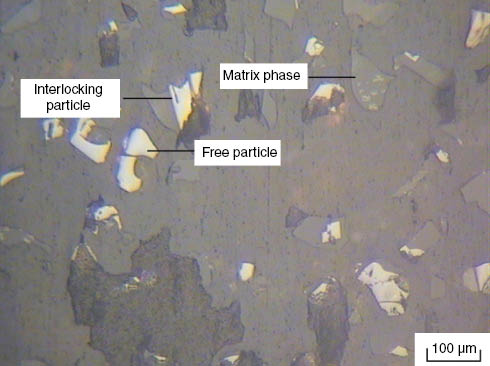
Microscopy image of modified slag.
Degree of mineral liberation with different particle sizes.
| Particle size (μm) | ≥3/4 free particles (%) | 3/4~1/2 free particles (%) | 1/2~1/4 free particles (%) | <1/4 free particles (%) |
|---|---|---|---|---|
| 150~250 | 47.53 | 19.75 | 19.76 | 12.96 |
| 74~150 | 58.15 | 19.87 | 11.02 | 10.96 |
| 48~74 | 37.93 | 10.76 | 5.12 | 5.43 |
| 38~48 | 78.69 | 5.69 | 5.87 | 3.41 |
| -38 | 85.33 | 5.32 | 5.36 | 3.99 |
After the grinding process, there are two types of particles: free particles and interlocking particles. As such, the free particles are rutile, and the interlocking particles are composed of the rutile and the matrix phase. According to the reference [11], there are two liberation ways for minerals: one is detachment liberation, and the other is size reduction liberation. In detachment liberation, the phases in locked particles separate from each other along the common boundary; it is an ideal and energy-saving liberation way. Size reduction liberation is a way of liberation due to the regulatory volume decrease of particles. However, during actual production process, most mineral phases cannot be separated completely from the matrix phase; a particle which has more than 75% of mineral phase is suitable for separation. The experiment results in Figure 8 and Table 5 show that the liberation degree increases as the particle size decreases. When the particle size is 150~250 μm, the degree of libration for rutile is 47.53%, while when the particle size is 38~48 μm, the degree of libration of rutile is 85.03%. Furthermore, the liberation degree increases slowly when the particle size is less than 74 μm, which indicates that the liberation way of rutile is detachment liberation.
A group of experimental results of open-circuit mineral processing.
| Products | Yield (%) | TiO2 (%) |
|---|---|---|
| Concentrate | 20.02 | 66.15 |
| Middling | 8.31 | 15.35 |
| Tailings | 8.37 | 12.56 |
3.3.2 Results of gravity separation
Based on the analysis and experimental results in this work, gravity separation is carried out via open-circuit mineral process; Table 5 is a group of experimental results of open-circuit mineral processing. Table 6 shows the chemical composition of middling and tailings (mass fraction, %).
Chemical composition of middling and tailings (mass fraction, %).
| CaO | MgO | TiO2 | Al2O3 | SiO2 | Fe2O3 | Others | |
|---|---|---|---|---|---|---|---|
| Middling | 29.33 | 9.85 | 11.07 | 15.15 | 29.76 | 4.14 | 0.7 |
| Tailings | 21.02 | 9.18 | 7.15 | 18.03 | 43.37 | 0.40 | 0.85 |
As shown in Tables 5 and 6, there are three products during the gravity separation process which are concentrate, middling and tailings. The middling and tailings can be used as raw materials to produce cement [12]. There is 66.15% TiO2 in the concentrate, which is not propitious to be applied in the titanium industry; other methods are still necessary to remove the impurities in the concentrate. Thus, alkali and acid leaching method is implemented in order to remove the non-titanium components in this work.
3.4 Leaching process of non-titanium components
As shown in Table 1, the composition of the slag is complex. In general, the stoichiometry of metallic oxides dissolution in alkaline and acid solutions can be represented by Equations (5)–(8):
The leaching behavior of silicon components is complex; according to our experiment results and other research results [13], the silicon components are floating in aqueous solution in the form of orthosilicic acid (H4SiO4), which can be separated by still stratification method from the aqueous solution.
3.4.1 Effect of NaOH solution concentration on the leaching of non-titanium component
Previous studies [14–17] show that hydrochloric acid leaching proceeds readily; thus, the control step of the leaching process is sodium hydroxide solution leaching process. The experiment results under different NaOH solution concentrations are shown in Figure 4.
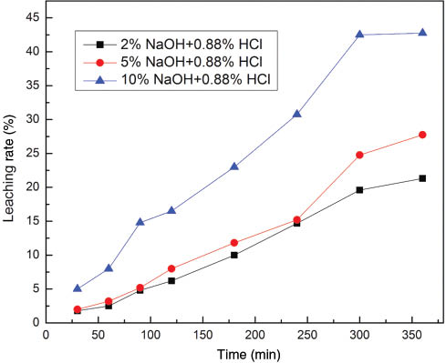
Effect of NaOH concentration on leaching rate of non-titanium components.
As we all know, the viscosity of the leaching system increases as NaOH concentration increases, which impedes the diffusion process of the leaching reagents and the reaction product thereby affecting the leaching rate of non-titanium component. However, as shown in Figure 4, the leaching rate of non-titanium component increases as the NaOH concentration increases. This indicates that the leaching process is not controlled by out-diffusion process.
3.4.2 Effect of temperature on the leaching rates of non-titanium components
In this paper, at 10 wt% NaOH concentration, the effect of temperature has been studied at 313, 333, 353 and 373 K. Figure 5 shows the effect of temperature on leaching rate of non-titanium components.
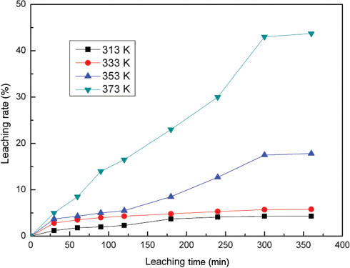
Effect of temperature on the leaching of non-titanium component.
Figure 5 illustrates that non-titanium components dissolution increases dramatically as the temperature increases. However, at high temperature (373 K) it is found that the initial non-titanium components dissolve faster when the leaching time is less than 300 min. This is because higher temperature is more conducive to the chemical reaction process, which is consistent with other extracting processes [18–22]. As such, higher temperature can promote the chemical reaction between NaOH and solid particles. Based on the experimental results in Figure 5, we choose 373 K as the optimal leaching temperature.
3.4.3 Effect of solid-to-liquid ratio on the leaching of non-titanium component
Figure 6 summarizes the effect of solid-to-liquid ratio on the leaching rate of non-titanium component.
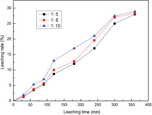
Effect of solid-to-liquid ratio on the leaching of non-titanium component.
As shown in Figure 6, the leaching rate of non-titanium components in the modified slag decreases as the solid-to-liquid ratio increases. The solid-to-liquid ratio is a critical factor for most of the leaching process. Liquid-solid ratio affects the viscosity of the leaching system; the viscosity of the leaching system decreases as the solid-to-liquid ratio increases. Low solid-liquid ratio means fewer particles in the system with the same volume of solution, which is conducive to improve the diffusion process of the leaching system. Moreover, it can be seen that the leaching rate did not greatly change with varying solid-to-liquid ratio, which also can be found in other leaching processes [18–22]; thus, we can choose 1:5 as the optimal solid-to-liquid ratio, and less water would be consumed during the leaching process.
3.4.4 Leaching kinetics of non-titanium component
Figure 7 shows the back-scattering microscopic morphology of particles before and after leaching process.
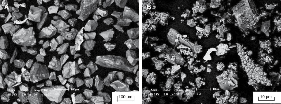
SEM micrograph of particles before and after leaching process: (A) before leaching; and (B) after leaching.
It can be seen that the particles without being leached are featured as compact solids with a smooth surface; the surfaces of the particles become rough and porous after leaching process due to the chemical reactions. The particle size decreases as the leaching reactions proceed. The morphology and chemical analysis of the slag illustrate that the leaching process of silicon and aluminum component can be described by the unreacted shrinking core model, the equation of which is shown as [16, 17, 22]
where x is the reaction rate of the impurities in the slag, KM is the mass-transfer coefficient of the reactant from reagents in liquid boundary layer, R0 is the particle size of the slag, De is the mass-transfer coefficient of the reactant in the product layer, krea is the reaction rate constant, t is the reaction time, M is the molar weight of the slag, C0 is the concentration of the reactant when the leaching process is begun, ρ is the density of the slag, and σ is the coefficient of NaOH.
When the leaching process is controlled by the liquid boundary layer diffusion process, the kinetics equation can be represented by [16, 17, 22]
Likewise, when the leaching process is controlled by solid product layer diffusion process, the kinetics equation can be represented by [16, 17, 22]
Figure 8 shows the relationship fitted by kinetics functions between non-titanium leaching rate and leaching time at 373 K.
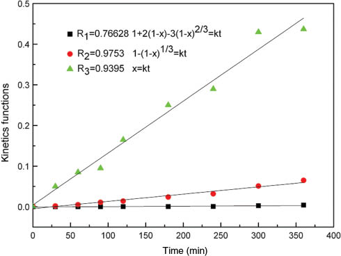
Non-titanium leaching rate vs. time at 373 K fitted by kinetics functions.
As can be seen in Figure 8, the linearly dependent coefficients of the above fitting lines are 0.76628, 0.9753 and 0.9375; thus, the optimal kinetics equation of the leaching process is
Figure 9 is a plot of leaching kinetics at different leaching temperatures.
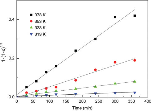
Plot of leaching kinetics under different reaction temperatures.
To reveal the control step of the leaching process, kinetics experimental results in Figure 5 are calculated at different temperatures, and the calculating results are shown in Figure 10.
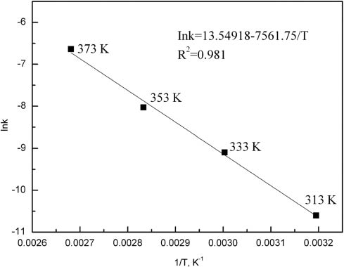
Nature logarithm of reaction rate constant vs. reciprocal temperature.
Leaching rates of non-titanium with different temperatures are fitted, and the value of k is obtained. The apparent activation energy can be calculated based on Arrhenius equation [16, 17, 22]:
where E is the apparent activation energy, A is pre-exponential factor, and R is the molar gas constant. After calculating, the value of E in equation (14) is obtained to be E=62.868 kJ/mol.
3.5 Circulatory leaching and preparation of synthetic rutile
3.5.1 Circulatory leaching and solution purification process
No emission of waste water is expected during the production process in this work; thus, circulatory leaching and solution purification process are necessary to be carried out to make the process more environmental.
The leaching solution of sodium hydroxide mainly consists of OH-, AlO2- and Na+; the CO2 gas could be applied and piped into the leachate to adjust the acidity of the leachate in order to make AlO2- precipitate in the form of Al (OH) 3; after several leaching cycles, when sodium and carbonate ions reach a certain concentration, cooling crystallization method can be applied to remove most of the sodium and carbonate ions. Likewise, the hydrochloric acid leaching leachate usually includes Fe3+and Mg2+. Sodium hydroxide can be added into the leachate to adjust acidity in order to make Fe3+and Mg2+ precipitate in the form of Fe (OH)3 and Mg (OH)2 to remove the Fe3+ and Mg2+ from the leachate. Table 7 shows analysis results of main metal ions in the leachate before and after precipitation.
Analysis results of main metal ions in the solution.
| Solution | Fe3+/(g/l) | Al3+/(g/l) | Ca2+/(g/l) | Mg2+/(g/l) |
|---|---|---|---|---|
| Circulatory leaching 1 | 0.13 | 2.75 | 3.86 | 0.66 |
| Circulatory leaching 2 | 0.18 | 3.42 | 4.59 | 0.82 |
| Circulatory leaching 3 | 0.24 | 3.96 | 5.16 | 1.01 |
| After precipitate | <0.001 | <0.001 | <0.001 | <0.001 |
3.5.2 Results of synthetic rutile preparation experiment
Based on the theoretical analysis experimental results in this paper, synthetic rutile preparation experiment is carried out by the route of HTM-gravity separation-alkali and acid leaching. Table 8 is the chemical analysis results of the product.
Chemical analysis results of rutile (mass fraction, %).
| TiO2 | SiO2 | Al2O3 | MgO | CaO | Fe2O3 | Others |
|---|---|---|---|---|---|---|
| 93.75 | 2.78 | 0.98 | 0.58 | 0.87 | 0.12 | 0.82 |
It can be observed from Table 8 that there is not much difference in the composition between the final products of the present study and typical synthetic rutile; the products are ideal material which can be used in titanium industry.
3.6 Proposed environmental route for comprehensive utilization of the slag
Based on the experimental results in this work, combined with the other mature and applicable technologies in metallurgy industry, an environmental route for comprehensive utilization of the slag is proposed, which is shown in Figure 11.
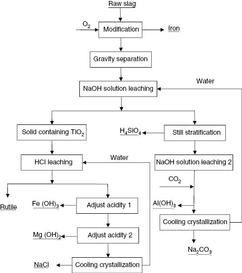
Flow sheet for the comprehensive utilization of Ti-bearing blast furnace slag.
As shown in Figure 11, the iron in the slag can easily be separated by spontaneous sedimentation method due to its larger density than the liquid slag; then gravity separation process is implemented in order to separate the rutile phase from matrix phase, and then leaching process is carried out in order to get high-quality synthetic rutile. After the alkali leaching process, the silicon components transformed into H4SiO4 in forms of colloid, which floats in solution and is easy to separate, while the aluminum components exist in the solution in the form of AlO2-. CO2 gas could be piped into the solution to adjust the solution acidity to make the aluminum components precipitate in the form of Al(OH) 3, and the by-product is Na2CO3, which can be separated by cooling crystallization method. The purified water can be applied in the leaching process again [23]. Likewise, there are Fe3+and Mg2+ in the acid leaching solution; NaOH can be used to adjust the pH in order to make the Fe3+and Mg2+ precipitate in the form of Fe(OH)3 and Mg(OH)2, and the by-product is NaCl, which can be separated by cooling crystallization method.
4 Conclusions
An environmental production procedure which can achieve the recovery of titanium and iron from Ti-bearing blast furnace slag is implemented. Based on the environmental production procedure to extract titanium component and iron from Ti-bearing blast furnace slag, an environmental route for comprehensive utilization of the slag is proposed in this work. The following conclusions can be obtained:
Most of the titanium components in Ti-bearing slag transform into rutile phase after modification process, which is quite conducive to the separation of titanium components.
The metallic iron in the slag would settle down to the bottom of the crucible during the HTM process, which does not require heating in industrial production, and it can be separated from the slag by sedimentation.
Leaching behavior of non-component in the slag is investigated; the optimal leaching temperature is 373 K, the optimal NaOH concentration is 10%, and the leaching activation energy is 62.868 kJ/mol.
Circulatory leaching and preparation of synthetic rutile experiments are accomplished, and the final product in this work can be used in titanium industry.
About the authors

Wu Zhang obtained his PhD from the School of Materials and Metallurgy, Northeastern University, China in 2013. Currently, he serves as an Associate Professor at the School of Materials Science and Engineering, Shenyang Ligong University, China. He is engaged in dealing with industrial solid waste and extracting valuable components in Ti-bearing blast furnace slag.

Li Zhang is an Associate Professor at the School of Materials and Metallurgy, Northeastern University, China. Between 2004 and 2005, he served as a postdoctor fellow in the Korean Academy of Sciences. He is known for his work on comprehensive utilization of Ti-bearing blast furnace slag.

Yuhai Li is a Professor at the School of Materials Science and Engineering, Shenyang Ligong University, China. He worked as a postdoctor fellow at the Institute of Metal Research, Academia Sinica. He is a member of Shenyang Human Materials and Heat Treatment Association. He has done a lot of work in making comprehensive utilization of Ti-bearing blast furnace slag from 2011 to date.

Xin Li obtained her PhD from the School of Chemical Engineering, Dalian University of Technology, China. Currently, she is an Associate Professor at School of Materials Science and Engineering, Shenyang Ligong University, China. She is engaged in extracting valuable components in industrial solid waste.
Acknowledgments
The authors gratefully acknowledge the financial support from the National Natural Science Foundation of China no. 51304139.
Conflict of interest statement: The authors declare no competing financial interest.
References
[1] Al-Khatib IA. Waste Manage. 2015, 36, 323–330.Search in Google Scholar
[2] Alibardi L, Cossu R. Waste Manage. 2015, 36, 147–155.Search in Google Scholar
[3] Ambily PS, Umarani C, Ravisankar K, Prem PR, Bharatkumar BH, Iyer NR. Constr. Build Mater. 2015, 77, 233–240.Search in Google Scholar
[4] Zhang L, Zhang LN, Wang MY, Li GQ, Sui ZT. Miner. Eng. 2007, 20, 684–693.Search in Google Scholar
[5] Sui ZT. Acta Mater. 1999, 47, 1337–1344.Search in Google Scholar
[6] Li J, Zhang ZT, Zhang M, Guo M, Wang XD. Steel Res. Int. 2011, 82, 613–614.Search in Google Scholar
[7] Li J, Wang XD, Zhang ZT. ISIJ Int. 2011, 51, 1396–1402.Search in Google Scholar
[8] Wang MY, He YH, Wang XW, Lou TP, Sui ZT. Nonferrous Met. Soc. China 2007, 17, 584–588.10.1016/S1003-6326(07)60078-8Search in Google Scholar
[9] Zhang W, Zhang L, Feng NX. Adv. Mater. Res. 2013, 611, 363–366.Search in Google Scholar
[10] Winkler MKH, Bassin JP, Kleerebezem R, van der Lans RGJM, van Loosdrecht MCM. Water Res. 2012, 12, 3897–3902.Search in Google Scholar
[11] Tuazon D, Corder G, Powell M, Ziemski M. Miner. Eng. 2012, 29, 65–71.Search in Google Scholar
[12] Zhang W, Zhang L, Zhang JH, Feng NX. Ind. Eng. Chem. Res. 2012, 51, 12294–12298.Search in Google Scholar
[13] Mazzocchitti G, Giannopoulou I, Panias D. Hydrometallurgy 2009, 4, 327–332.10.1016/j.hydromet.2008.12.001Search in Google Scholar
[14] Geveci A, Topkaya Y, Ayhan E. Miner. Eng. 2002, 15, 885–888.Search in Google Scholar
[15] Deakin D, West LJ, Stewart DI, Yardley BWD. Waste Manage. 2001, 21, 265–270.Search in Google Scholar
[16] Johnson JA, McDonald RG, Muir D, Tranne JP. Hydrometallurgy 2005, 78, 264–270.10.1016/j.hydromet.2005.04.002Search in Google Scholar
[17] Parhi PK, Park KH, Senanayake G. J. Ind. Eng. Chem. 2013, 19, 589–594.Search in Google Scholar
[18] Rodriguez MH, Rosales GD, Pinna EG, Suarez DS. Hydrometallurgy 2015, 156, 17–20.10.1016/j.hydromet.2015.05.006Search in Google Scholar
[19] Yin SH, Li SW, Peng JH, Zhang LB. RSC Adv. 2015, 5, 48659–48664.Search in Google Scholar
[20] Xiao J, Li FC, Zhong QF, Bao HG, Wang BJ, Huang JD, Zhang YB. Hydrometallurgy 2015, 155, 118–124.10.1016/j.hydromet.2015.04.018Search in Google Scholar
[21] Malenga EN, Mulaba-Bafubiandi AF, Nheta W. Hydrometallurgy 2015, 155, 69–78.10.1016/j.hydromet.2015.04.004Search in Google Scholar
[22] Ju ZJ, Wang CY, Yin F. Int. J. Miner. Pro. 2015, 138, 1–5.Search in Google Scholar
[23] Aryal N, Reinhold DM. Ecol. Eng. 2015, 78, 53–61.Search in Google Scholar
©2015 by De Gruyter
This article is distributed under the terms of the Creative Commons Attribution Non-Commercial License, which permits unrestricted non-commercial use, distribution, and reproduction in any medium, provided the original work is properly cited.
Articles in the same Issue
- Frontmatter
- In this issue
- Editorial
- Electrification of chemistry – what is the synergy between plasma synthesis and chemical plant modularization?
- Original articles
- Optimization of biodiesel synthesis under simultaneous ultrasound-microwave irradiation using response surface methodology (RSM)
- The synthesis of optically enriched 2-benzyl- 3-nitropropionic amide
- Cobalt, nitrogen-codoped carbon quantum dots as a synergistic catalyst for oxygen reduction reaction
- Sulfonated poly (arylene ether sulfone) proton exchange membranes for fuel cell applications
- Preparation of high surface area activated carbon from Eupatorium adenophorum using K2CO3 activation by microwave heating
- An environmental procedure to extract titanium components and metallic iron from Ti-bearing blast furnace slag
- Recovery of molybdenum from alkali leaching solution of low-grade molybdenum concentrate by ion exchange
- Impacts of ultrasound on leaching recovery of zinc from low grade zinc oxide ore
- Study on the calcination experiments of rare earth carbonates using microwave heating
- Conference announcement
- Conferences 2015–2017