Sulfonated poly (arylene ether sulfone) proton exchange membranes for fuel cell applications
-
Vaishnav Kiran
Vaishnav Kiran received her Bachelor’s degree in 2001 from Punjab University Chandigarh, India and her Master’s degree in 2003 from GNDU Amritsar, India. She is currently pursuing her PhD degree at the National Institute of Technology Hamirpur H.P., India, on the subject of the synthesis of proton exchange membranes, for proton exchange membrane fuel cells. Her research interests include polymer chemistry and the emerging area of non-conventional energy sources like microbial fuel cells, etc. She has six publications in international and national journals, and has presented at various conferences.
Bharti Gaur is an Associate Professor in the Department of Chemistry, at the National Institute of Technology (NIT) Hamirpur, Himachal Pradesh, India. She received her BSc degree in 1986 from St. Bedes College Shimla, India. She did her post-graduation studies in Organic Chemistry at Sardar Patel University, Anand, Gujarat, India, in 1988. She obtained her PhD degree from HBTI Kanpur, India, in 1993. She taught in a number of undergraduate and postgraduate institutes before joining the NIT Hamirpur as Assistant Professor in 2010. She has more than 25 research papers in international journals and conferences and has filed two patents in the field of energetic binders for solid rocket propellants. Her current research interests include microbial fuel cells, the synthesis of proton exchange membrane for fuel cells, nanocomposites, the synthesis of adhesives, and coatings.


Abstract
Sulfonated poly (arylene ether sulfone) membranes were synthesized by direct copolymerization of 4,4-bis (4-hydroxyphenyl) valeric acid, 4,4′-difluorodiphenyl sulfone and synthesized sulfonated 6F-bisphenol-A/bisphenol-A as novel proton exchange membranes for fuel cell applications. Prepared membranes were subsequently crosslinked with synthesized 6F-bisphenol-A based epoxy resin (EFN) by thermal curing reaction keeping in view the resilience and toughness of the membranes. The structural characterization was done by using Fourier transform infrared (FTIR), 1H nuclear magnetic resonance (NMR) and 13C NMR techniques. Proton conductivity of the membranes was determined by a four-point probe technique. Methanol permeability was determined by using a diffusion cell in which concentration of the liquids was determined by UV-spectroscopic technique. The enhancement in mechanical properties determined by a universal testing machine and also a better oxidative stability were observed for the crosslinked membranes. However, a decrease in their water and methanol absorption, ion exchange capacity, proton conductivity and methanol permeability was observed. This was due to the reduction in the numbers of ionic channels in case of crosslinked membranes which was confirmed by carrying out morphological analysis of the membranes using atomic force microscopy. In addition, X-ray diffraction measurement by XPERT-PRO diffractometer was also used for structural characterization. Crosslinked membranes showed better thermal stability as determined by thermogravimetric analysis and differential scanning calorimetry.
1 Introduction
The need for power generation and clean energy throughout the world has spurred the search for alternative energy resources. Fuel cell technology has achieved an important place in the application of alternative energy due to low pollution to the environment and high energy conversion efficiency. Among the many types of developed fuel cells, such as the phosphoric acid fuel cell, molten carbonate fuel cell, solid oxide fuel cell, alkaline fuel cell and the proton exchange membrane fuel cell (PEMFC), the PEMFCs are considered as a promising contender of sanitized power source, because of their high energy efficiency and low pollution level. The microbial fuel cell (MFC), a type of PEMFC in which microorganisms act as catalyst, has the potential to be used as an environment friendly energy device. But the ambient temperature operating condition of MFCs is the limitation of their usage [1].
The use of platinum (Pt) as catalyst in fuel cells is challenging because of the risk of carbon monoxide (CO) poisoning, as CO binding to the Pt is a thermally reversible process at temperatures >100°C. Therefore, these led to investigating the proton exchange membranes (PEMs) which can effectively operate at temperatures >100°C. PEMs are the cardinal components of PEMFCs and play the dual duty of transferring the electrons from anode to cathode as well as providing a barrier to fuel gas cross-leaks between the electrodes. These membranes also determine the cost and performance of the fuel cell system. The use of polymeric materials such as PEMs has received great impetus in the recent past, because the replacements of the electrolyte solutions by ionically conductive polymeric membranes are advantageous in reducing the size and weight of fuel cells. This makes fuel cells the premier candidates, both for automotive as well as stationary power applications [2]. The current state-of-the-art of PEMFC technology is based on perfluorosulfonic acid (PFSA) ionomers such as Nafion because of its long-term stability and high proton conductivity [3]. However, these PFSA ionomers do not meet the more challenging criteria required for high temperature and low relative humidity operating fuel cells. The other limitations such as fuel crossover, the above-mentioned CO poisoning and high cost are of concern and efforts are being made to opt for alternative membrane materials which can overcome these drawbacks [4, 5].
In the recent years a varied class of aromatic hydrocarbon polymers as backbone structures have been synthesized and evaluated, in terms of their applicability as PEMs. These include poly(arylene ether ketone)s, poly(arylene ether sulfone)s (PAESs) [6–11], poly(arylene ether nitrile)s [12, 13], poly(phthalazinone arylene ether)s [14, 15], polyimides [16–18]. Extensive work has also been carried out on polybenzimidazole based membranes which represents the class of PEMs having acid-base interactions and are suitable for high temperature operating fuel cell applications. These membranes can operate at higher temperatures (120°C–~200°C), and thus can enhance the CO tolerance of the catalyst. Polybenzimidazole-based PEMs have been extensively studied, in the form of their complexes with phosphoric acid. The unique hydration capabilities of the benzimidazole heterocycle, along with their high thermal and mechanical integrity, make them highly suitable for their evaluation as high temperature PEMs [19–22]. PAESs in combination with carbon nanotubes and inorganic fillers have also been studied by researchers as PEMs [23–28]. Among the promising candidates for PEM materials, sulfonated poly (arylene ether sulfone)s (SPAESs) are the well-known engineering thermoplastics with excellent thermal and chemical resistance. The functionalization of the ionic groups such as carboxylic acid and sulfonic acid groups onto the backbone or onto the pendant side chains could improve the hydrophillic character and make them gain different properties from hydrophobic backbone. SSPAESs are a reasonably good choice for high temperature operating PEMFCs. Apart from possessing adequate mechanical properties with high thermal and chemical resistance, these are also more economical compared with Nafion.
In the present work we have endeavored to synthesize the novel SPAES membranes via an aromatic substitution copolymerization reaction. With the purpose to enhance proton conductivity of the membranes, a monomer 4,4-bis(4-hydroxyphenyl) valeric acid (DPA) containing a carboxylic acid group on the flexible aliphatic side chain of the aromatic backbone has been chosen, on the assumption that it can provide protons and help in the nanophase separation of the hydrophilic and hydrophobic domains. The monomers 4,4′-isopropylidenediphenol (BPA) and 4,4′-(hexafluoroisopropylidene) diphenol (6F-BPA) help in enhancing the film forming properties [29]. Concurrently, with the aim of increasing the mechanical integrity of the membranes, the pendant carboxylic groups of DPA co-monomer have been crosslinked with oxirane rings of the synthesized 4,4′-(hexafluoroisopropylidene) diphenol based novolac epoxy resin (EFN). To the best of our knowledge the crosslinking of the SPAES membranes using DPA along with sulfonated BPA (S-BPA), 6F-BPA and 4,4′-difluorodiphenylsulfone (DFDPS) as co-monomers with EFN have not yet been reported. The membranes before and after crosslinking have been characterized to evaluate their properties such as ion exchange capacity, water/methanol uptake, proton conductivity, oxidative stability, morphology, mechanical strength and thermal stability as PEMs for fuel cell applications.
2 Materials and methods
2.1 Materials
6F-bisphenol-A (6F-BPA, 97%, Sigma Aldrich Chemie Gmbh, Germany), formaldehyde (37-41%, Merck Specialities Pvt. Limited, Mumbai, India), p-toluene sulfonic acid (PTSA, 98%, Merck Specialities Pvt. Limited, Mumbai, India), methyl isobutyl ketone (MIBK, 99.5%, Merck Specialities Pvt. Limited, Mumbai, India), epichlorohydrin (ECH, 98%, Loba Chemie Pvt. Limited, Mumbai, India) and sodium hydroxide (NaOH, 98%, Loba Chemie Pvt. Limited, Mumbai, India) were used for the synthesis of EFN. Bisphenol-A (BPA, 97%, Alfa Aesar Chemicals, Johnson Mathey Company, Heysham, England), DPA (97%, Alfa Aesar Johnson Mathey Company, Heysham England), DFDPS (99%, Sigma Aldrich Chemie Gmbh, Germany),dimethyl sulfoxide (DMSO, 99.9%, Sigma Aidrich Chemie Gmbh, Germany), potassium carbonate (K2CO3, 99.9%, Loba Chemie Pvt. Limited, Mumbai, India), toluene (99%, Thermo Fisher Scientific Pvt. Limited, Mumbai, India) and hydrochloric acid (HCl, 35–38%, Thermo Fisher Scietific Pvt. Limited, Mumbai, India) were used for synthesizing SPAES membranes. Sulfuric acid (97-99%, Thermo Fisher Scientific Pvt. Limited, Mumbai, India).
2.2 Synthesis of EFN (Scheme 1)
A 40 ml MIBK solution containing 6F-BPA (0.05 mol) and PTSA (0.0014 mol) were added to a 250 ml three-necked round bottom flask equipped with a mechanical stirrer and dean and stark trap with a reflux condenser. Nitrogen gas was purged for 30 min and the reaction solution was heated to 100°C with stirring. A total of 0.08 mol of formaldehyde solution (37–41%) was added to the reaction mixture drop wise. Then, the reaction mixture was heated to 120°C with constant stirring and maintained at this temperature for 5 h. The condensation of novolac resin is a reversible process; therefore 0.13 mol of water generated during the reaction was removed as an azeotropic mixture with MIBK. The reaction mixture was cooled to room temperature and washed with deionized water several times until it became neutral. The solution was then distilled at 120°C in order to remove the MIBK solvent. The product was then washed with a mixture of water/methanol (7/3 v/v) several times to remove the unreacted 6F-BPA. A red brown solid product was obtained after vacuum drying at 60°C for 48 h.

Synthesis of EFN.
To the above dried product of 6F-BPA novolac, ECH (8 mol for every phenolic group of novolac resin), isopropyl alcohol (0.83 mol) were added to a 250 ml three necked round bottom flask equipped with a mechanical stirrer and a condenser. After increasing the reaction temperature to 70°C with constant stirring, 0.078 mol of 20 wt% aqueous solution of NaOH was added drop wise into the reaction solution for a period of 1 h. The system was maintained at 70°C for another 4 h with constant stirring. The reaction product in the flask was washed several times with deionized water to remove the sodium chloride (NaCl). The product was dissolved in toluene and filtered in order to remove the residual salt. Toluene and excess of ECH were distilled off under reduced pressure. Finally the product obtained was dried at 60–70°C under vacuum for 48 h.
2.3 Synthesis of sulfonated 6F-bisphenol-A (S-6F-BPA) and S-BPA (Scheme 2)
6F-Bisphenol-A (0.059 mol) and sulfuric acid (40 ml) were added to a 250 ml round bottom flask equipped with overhead mechanical stirrer and a condenser. The reaction mixture was stirred vigorously at 40°C for 18 h. After 18 h the reaction mixture was poured into 200 ml ice bath stirred with magnetic stirrer, and further neutralized with 2 m NaOH solution to a final pH 8. To this solution 1.72 mol of NaCl was added and allowed to stand overnight. Finally the precipitates (ppts) were filtered and recrystalized from a mixture of methanol and water (9/1v/v). A similar procedure was followed for the synthesis of S-BPA, but the reaction was carried out at 30°C. The ppts of S-BPA were recrystalized from a mixture of isopropyl alcohol and water (10/1 v/v) in order to obtain high yield [30].

Synthesis of (A) S-6F-BPA, (B) S-BPA.
2.4 Synthesis of SPAES copolymers (Scheme 3)
SPAES copolymer (6F-SPAES) was synthesized in a 250 ml three necked round bottom flask equipped with a mechanical stirrer and dean and stark trap. DPA (0.012 mol), S-6F-BPA (0.012mol) and 35 ml of DMSO were placed into the reaction flask. To this reaction mixture, K2CO3 (0.06 mol) was added and stirred at 80°C for 8 h for producing reactive phenolate ions. Then DFDPS (0.025 mol), 17 ml of toluene and 15 ml of DMSO were added, the temperature was increased to 150°C, the reaction mixture was stirred for 4 h in order to dehydrate the system. After this, the temperature was increased to 180°C with constant stirring; the reaction was carried out at this temperature for another 20 h until the reaction mixture became very viscous. After cooling, the solution was dissolved in DMSO and then filtered. The precipitation of the copolymer was carried out by adding isopropyl alcohol to the filtrate. The ppts were filtered and dried at 70°C. A similar procedure was followed for the synthesis of BPA-SPAES copolymer.

Synthesis of 6F-SPAES copolymer.
2.5 Preparation of membranes and their crosslinking (Scheme 4)
One gram of BPA-SPAES or 6F-SPAES copolymer was dissolved in 10 ml of DMSO and constantly stirred until homogeneous solutions were obtained. The resulting solutions were directly cast onto the glass plates and dried at 70–80°C for 24 h to obtain the corresponding pristine membranes.
The crosslinking of the above SPAES copolymers was done by dissolving these copolymers in DMSO at 30°C in a 50 ml round bottom flask and further adding EFN to each of these samples, respectively. The weight ratio of EFN to SPAES copolymer was varied within the range 11–33%. The crosslinking reaction between SPAES and EFN was carried out at 70–80°C for 24 h with constant stirring. The solution was then filtered and cast onto the glass plates and dried at 70–80°C for 24 h; the temperature was then subsequently raised to 150°C for another 5 h. The membranes thus obtained were dipped in 1 m HCl solution for 48 h at room temperature for their proton exchange.

Crosslinking of 6F-SPAES membrane with EFN.
2.6 Characterization
2.6.1 Structural characterization:
Fourier transform infrared (FTIR) spectra of the samples were recorded by using Perkin Elmer 1600 FTIR spectrophotometer in the range of 4000–400 cm-1 on the of KBr pellets. 1H nuclear magnetic resonance (NMR) and 13C NMR spectra were recorded on a BRUKER AVANCE II 400 NMR spectrometer using deuterated DMSO as solvent, and tetra methyl silane as the internal standard.
2.6.2 Ion exchange capacity (IEC):
IEC was determined by the titration method. The membrane samples in acid form were immersed in 1 m NaCl solution for 48 h to liberate the H+ ions and the H+ ions in the membrane were replaced by Na+ ions. The liberated H+ ions were titrated against 0.01 m NaOH solution using phenolphthalein as an indicator. The IEC was calculated from the following formula.
2.6.3 Swelling property:
The water and methanol absorption of the membranes were determined by measuring the change in the dry and swollen membranes. Weights of the dry membranes were measured after drying the membranes at 120°C for 24 h. The percentage of water and methanol absorption was calculated by the following formula.
where Ww and Wd are the weights of the wet and dry membranes, respectively.
2.6.4 Proton conductivity:
The conductivity of the membranes was checked at room temperature by the four-point probe technique. The four probes arrangement was attached with Keithley 6221 sourcemeter and Keithley 2182A nanovoltmeter. The membranes were cut into 2×2 cm2 and immersed in deionized water for 12 h before the measurement. The hydrated membranes were mounted onto the cell and an alternating current of 0.5 mA was applied to the cell. The conductivity was calculated with the following equation.
2.6.5 Methanol permeability:
Methanol permeability was determined by using a diffusion cell consisting of two compartments A and B which were partitioned by a membrane sample. One M solution of methanol was placed on one side (A) and water was placed on other side (B) of the diffusion cell. Both the compartments were magnetically stirred continuously during the permeation experiments to ensure uniformity. The concentration of water and methanol in the compartments A and B, respectively, was measured using T80 UV-VIS spectrometer and the following formula.
CA and CB are the concentrations of the methanol and VA and VB are the volumes of liquids in compartments A and B, respectively. t and t0 are the initial and final diffusion time, A and L are the area and thickness of the membranes, DK is the methanol permeability of the membranes.
2.6.6 Oxidative stability:
A small piece (0.2 g) of membrane sample was soaked in Fenton’s reagent (4 ppm FeSO4 in 6% H2O2) at 30°C and 80°C. The stability was evaluated by recording the time when membranes dissolved into the Fenton’s reagent.
2.6.7 Atomic force microscopy (AFM):
The surface morphology of the membranes was observed with an AFM system (Agilent 5500 SPM) at room temperature and room humidity. It was operated in tapping mode using a nanosensor silicon probe with spring constant of 10–130 N/m and a resonance frequency of 204–497 kHz. The membranes were soaked in distilled water for 12 h and on average three tests were taken for each sample.
2.6.8 X-ray diffraction (XRD) study:
The XRD diffraction patterns of SPAES membranes before and after crosslinking were obtained with a rotating anode XPERT-PRO diffractometer using Cu-Kα radiation source with a wavelength of 1.54060 Å.
2.6.9 Mechanical properties:
The mechanical properties of the membranes were measured by using Hounsfield universal testing machine (UTM) at the deformation rate of 2 mm/min. The films were cut into a size of 0.5×50 mm as reported by Ding et al. [31]. Thicknesses of the membranes were 0.3 mm and for each testing at least three measurements were made and the average value was calculated.
2.6.10 Thermal properties:
The degradation process and thermal stability of the membranes were examined using EXSTAR TG/DTA 6300 thermogravimetric analyzer (TGA). The TGA measurements were carried out under nitrogen atmosphere at a heating rate of 10°C/min with sample size of 10±1 mg from 100 to 900°C. The glass transition temperature of the prepared membranes was measured on Mettler differential scanning calorimetry (DSC) equipment. The samples were preheated under 200 ml/min nitrogen from room temperature to 150°C at a scanning rate of 10°C/min to remove moisture then cooled to 50°C and reheated from 50°C to 350°C at a heating rate of 10°C/min.
3 Results and discussion
3.1 EFN
Figure 1A shows the FTIR spectrum of EFN. The characteristic absorptions at 3057 and 2929 cm-1 were due to the stretching vibrations of aromatic rings and bridging methylene groups, respectively. A characteristic absorption band at 1299 cm-1 depicted the ring breathing frequency of the epoxy ring, the appearance of the band at 916 cm-1 proved the asymmetric ring deformation and the band at 762 cm-1 showed the symmetric ring deformation of the epoxy ring. The peaks in between 932 and 999 cm-1 were due to the presence of C-F bonds.
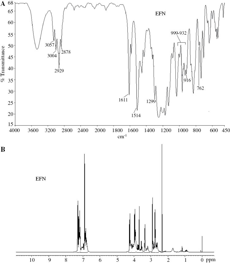
(A) FTIR and (B) 1H NMR spectra of EFN, respectively.
Figure 1B shows the 1H NMR spectrum of EFN. The spectrum showed proton resonance signals at 3.6–3.8 and 6.7–7.3 ppm due to -CH2 bridging and the aromatic protons, respectively. Characteristic proton resonance signals at 2.7–2.9, 3.3 and 3.9–4.2 ppm due to -O-CH2, -CH and -CH2 protons of the epoxy ring, respectively, were also observed.
3.2 S-BPA and S-6F-BPA monomers
Figure 2A and B represent the 1H NMR spectra of the S-BPA and S-6F-BPA, respectively. The proton (H1) adjacent to the sodium sulfonate group deshielded and appeared at 7.6 ppm due to the electron withdrawing nature of the sulfone group, and H2 and H3protons appeared at 6.7 and 7.1–7.3 ppm, respectively. The methyl protons (H4) of S-BPA in Figure 2A corresponded to the signal at 1.3 ppm.
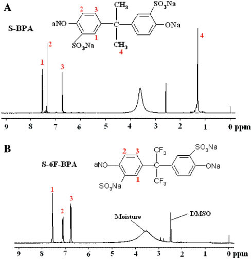
1H NMR spectra of (A) S-BPA and (B) S-6F-BPA.
3.3 BPA-SPAES, cr- BPA-SPAES and 6F-SPAES, cr-6F-SPAES membranes
Figure 3A and B showed the FTIR spectra of BPA-SPAES, 6F-SPAES and their crosslinked membranes, respectively. A characteristic absorption band at 1243 cm-1 suggested the C-O stretching vibrations of the carboxylic acid group. The appearance of a doublet at 1321 and 1295 cm-1 was due to the asymmetric stretching vibrations and the band at 1167 cm-1 was due to the symmetric stretching vibrations of O=S=O. Peaks at 570 and 621 cm-1 represented the S-O stretching vibrations of the pendant sodium sulfonate groups of BPA-SPAES and 6F-SPAES copolymers, respectively. The S-O peak in the case of BPA-SPAES appeared at a lower frequency due to the presence of the electron donating methyl groups in the case of the BPA monomer as compared with the -CF3 groups in the case of 6F-SPAES.
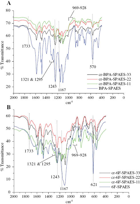
FTIR spectra of (A) BPA-SPAES and its crosslinked membranes and (B) 6F-SPAES and its crosslinked membranes, respectively.
In the crosslinked cr-BPA-SPAES membranes, a characteristic new absorption band was observed at 1733 cm-1 due to the C=O stretching vibrations of the ester linkages formed after the crosslinking of the BPA-SPAES membrane with EFN. The appearance of peaks between 928 and 969 cm-1indicated the stretching vibrations due to the presence of C-F bonds. Similar peaks were observed in the case of 6F-SPAES and cr-6F-SPAES membranes.
Figure 4A and B represented the 1H NMR spectra of 6F-SPAES and BPA-SPAES copolymers, respectively. The methyl protons (H10) of DPA appeared at 1.6 ppm and the methylene protons (H9, H8) of the pentanoic group of DPA showed resonating signals at 2.0 ppm and 2.5 ppm, respectively. The methyl protons (H11) of BPA appeared at 1.3 ppm. The aromatic protons (H1, H3) attached to the ortho positions of the electron withdrawing groups (sulfone and sodium sulfonate) appeared in the lower field region (7.9–8.0 ppm) in 6F-SPAES and at 7.3 ppm and 8.0 ppm in the case of BPA-SPAES, respectively. The H2, H4, H5 protons showed resonating signals from 7.1 to 7.8 ppm in 6F-SPAES and 6.6–7.2 ppm in the case of BPA-SPAES, respectively. A resonating signal for the aromatic protons (H6 and H7) appeared at 6.9–7.0 ppm in 6F-SPAES and from 6.3 to 6.5 ppm in BPA-SPAES. 13C NMR spectrum of BPA-SPAES depicted in Figure 4C showed a distinct signal for the carboxylic acid group carbon (C1) at 174 ppm. The peaks for the aromatic carbons were observed in the range of 117–135 ppm. The 147–161 ppm region showed peaks for the C-O carbons. The peaks corresponding to other carbons have also been identified.
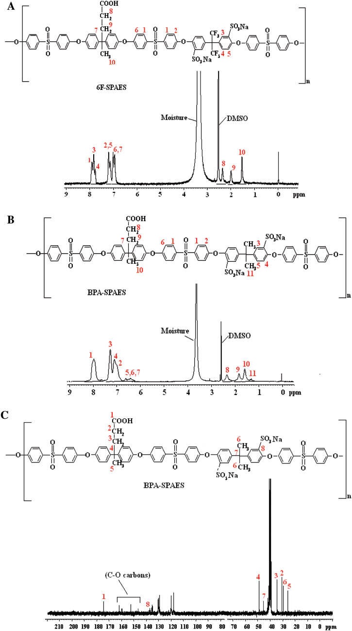
(A) and (B) 1H NMR spectra of 6F-SPAES and BPA-SPAES copolymers, (C) 13C NMR spectrum of BPA-SPAES copolymer, respectively.
3.4 IEC and water uptake
IEC is the number of moles of fixed -SO3- sites per gram of the polymer. It is an indicator of the extent of sulfonation as it tells about the exchangeable ions in the polymer backbone. It is determined by the titration method at room temperature and the values are given in Table 1. The water uptake of the BPA-SPAES membranes is shown in Figure 5 and similar results were also obtained for the 6F-SPAES membranes. The IEC capacity and water uptake in the case of pristine membranes were found to be higher than their corresponding crosslinked membranes, as the pristine membranes have a greater tendency to form the ionic channels through the pendant sulfonic acid and carboxylic acid groups.
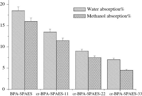
Water and methanol absorption.
IEC, proton conductivity, methanol permeability and selectivity ratio of the SPAES membranes.
| Membranes | IEC (meq/g) | Proton conductivity (S/cm) | Methanol permeability (cm2/s) | Selectivity ratio (Ss/cm3) |
|---|---|---|---|---|
| BPA-SPAES | 6.3×10⁻¹ | 7.7×10⁻³ | 5.6×10⁻⁶ | 1.37×10³ |
| cr-BPA-SPAES-11 | 5.2×10⁻¹ | 6.5×10⁻³ | 3.8×10⁻⁶ | 1.71×10³ |
| cr-BPA-SPAES-22 | 4.5×10⁻¹ | 4.7×10⁻³ | 2.9×10⁻⁶ | 1.62×10³ |
| cr-BPA-SPAES-33 | 3.2×10⁻¹ | 2.8×10⁻³ | 2.2×10⁻⁶ | 1.27×10³ |
| 6F-SPAES | 5.5×10⁻¹ | 5.6×10⁻³ | – | |
| cr-6F-SPAES-11 | 4.3×10⁻¹ | 4.4×10⁻³ | 2.7×10⁻⁶ | 1.62×10³ |
| cr-6F-SPAES-22 | 3.7×10⁻¹ | 2.9×10⁻³ | 1.9×10⁻⁶ | 1.52×10³ |
| cr-6F-SPAES-33 | 2.5×10⁻¹ | 1.4×10⁻³ | 1.0×10⁻⁶ | 1.40×10³ |
| Nafion 117a | 9.1×10⁻¹ | 10×10-3 | 2.0×10⁻⁶ | – |
a[32–34].
Water uptake is one of the major factors for determining the IEC and proton conductivity of the membranes. It acts as a medium for the transportation of the protons. According to Ionic cluster network model and Grothuss and vehicle mechanism the protons are transported in the form of H3O+, H5O2+, H9O4+ions through the hydrogen bonded ionic channels and the cationic mixtures in the water medium [32, 35–37]. Water allows the protons of the anodic compartment to smoothly transfer through the hydrocarbon based PEM to the cathodic compartment. Sulfonic acid groups are required for the formation of the ionic channels. In fully hydrated state the sulfonated polymers may slack immobile sulfonic acid groups and mobile protons in to the solution. The protons get transported from one sulfonic acid group to another in the form of hydronium ions. The crosslinked membranes showed 2–4% decrease in water uptake, which may be due to the unavailability of the protons of the carboxylic acid groups that might have participated in proton transportation in the pristine membranes.
3.5 Proton conductivity, methanol permeability and selectivity ratio
Proton conductivity and methanol permeability are the prime requirements for PEMs because high proton conductivity and low methanol permeability of the membranes make them highly suitable for direct methanol fuel cells. From the results tabulated in Table 1 it can be observed that proton conductivity of the pristine BPA-SPAES and 6F-SPAES membranes were higher than that of their corresponding crosslinked cr-BPA-SPAES and cr-6F-SPAES membranes, respectively. This was due to either the reduction or disconnectivity of the hydrophillic ion conductive network due to the bonding of the carboxylic acid groups of the membranes with oxirane rings of the EFN in the crosslinked membranes which may have caused reduction in proton conductivity. The close packing in the cases of cr-BPA-SPAES and cr-6F-SPAES membranes may have contributed towards a decrease in the methanol crossover. It can also be observed that the proton conductivity as well as the methanol permeability of the crosslinked cr-BPA-SPAES and cr-6F-SPAES membranes decreased with the increase in the percentage weight ratio of EFN.
In general to improve the performance of the PEMs in PEMFCs there should be high proton conductivity and low methanol permeability. Selectivity ratio is the ratio of the proton conductivity (σ) to methanol permeability (DK). The higher the value of σ/DK, the better will be the performance of the membrane. It is apparent from Table 1 that both crosslinked cr-BPA-SPAES and cr-6F-SPAES membranes with 11% weight ratio of EFN showed better selectivity than their corresponding pristine membranes. The selectivity ratio further decreased with the increase in the content of EFN.
3.6 Oxidative stability
Fenton’s reagent test was performed on all membranes. The membranes were soaked in 6% H2O2 and ferrous sulfate solution at room temperature and stirred continuously. Figure 6 showed the weight residues of the BPA-SPAES membranes as a function of time in Fenton’s reagent at 30°C, similar results were obtained for the 6F-SPAES membranes as mentioned in Table 2. This method has been used to stimulate the oxidation reaction of the membranes by the attack of free radical species (HO·and HOO·) of Fenton’s reagent [38–40]. The presence of highly electron withdrawing sulfone groups in the backbone of the polymeric chains and the pendant sulfonic acid groups as well as -CF3 groups might be responsible for the reduction of the electron density of the nearby aromatic rings and thus might enable the membranes to exhibit a better tolerance against the electrophilic attack by these hydroxyl radicals. From the results it was revealed that cr-BPA-SPAES and cr-6F-SPAES membranes were more stable against the oxidative attack as compared with their corresponding pristine BPA-SPAES and 6F-SPAES membranes. The improved oxidative stability of the crosslinked membranes was due to the formation of a three-dimensional infusible network structure via the reaction between the pendant carboxylic acid groups of the main polymeric chain and the oxirane ring of EFN. Moreover less water absorption by the crosslinked membranes also contributed towards the enhancement of their oxidative stability because the lower the water content, the lesser will be the attack via the oxidizing species present in water. However, hydroxyl radical species probably attacked the pendant carboxylic acid groups in the case of pristine membranes and hence caused a reduction in their oxidative stability.
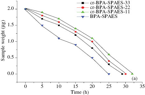
Oxidative stability of the BPA-SPAES and its cr-BPA-SPAES membranes at 30°C.
Mechanical properties and oxidative stability of the SPAES membranes.
| Membranes | Tensile strength (MPa) | Young’s modulus (MPa) | Elongation at break % | Oxidative stability (dissolved time in Fenton’s reagent) (h) | |
|---|---|---|---|---|---|
| 30°C | 80°C | ||||
| BPA-SPAES | 59.09 | 84.26 | 114.87 | 25 | 7 |
| cr-BPA-SPAES-11 | 87.73 | 185.77 | 173.03 | 33 | 11 |
| cr-BPA-SPAES-22 | 67.44 | 126.84 | 130.91 | 30 | 9 |
| cr-BPA-SPAES-33 | 50.72 | 116.29 | 49.68 | 29 | 8 |
| 6F-SPAES | – | – | – | 14 | 5 |
| cr-6F-SPAES-11 | 39.80 | 37.69 | 163.44 | 30 | 10 |
| cr-6F-SPAES-22 | 35.10 | 36.04 | 153.85 | 28 | 9 |
| cr-6F-SPAES-33 | 29.96 | 28.24 | 116.66 | 27 | 7 |
| Nafion | 32–43b | 249b | – | – | >6a |
a[9], b[34].
It was observed that membranes with excess of epoxy monomer (in the ratio of 22–33% by weight of EFN to SPAES) were found to be less stable as compared to crosslinked sulfonatred poly arylene ether sulfone membranes containing 11% EFN by weight. This was owing to that the off-stoichiometric mixtures contain latent sites [41] which could remain on the macromolecular structure and could become susceptible to the free radical attack.
3.7 Morphology of the membranes
The microscopic observation of the surface of the prepared membranes was investigated via the tapping mode atomic force microscopy (AFM). Tapping mode images of the membranes BPA-SPAES, 6F-SPAES and their crosslinked membranes are shown in Figure 7. Examination of the AFM images revealed the presence of light and dark spots, which indicated that the membranes had a phase separation consisting of two types of domains. The light colored spots corresponded to the hydrophilic domains and the dark area depicted the hydrophobic regions [42, 43]. It was observed that the hydrophilic domains of pristine membranes BPA-SPAES and 6F-SPAES in Figure 7A, B and E, F, respectively, seemed to be wider and more connected compared with their corresponding crosslinked membranes cr-BPA-SPAES-11 and cr-6F-SPAES-11 in Figure 7C, D and G, H, respectively. The continuity of the hydrophilic clusters depends upon the number of sulfonic and carboxylic acid groups. These acid groups containing small amounts of water may have aggregated to form ionic clusters which may provide larger proton transport channels. After crosslinking the number of connections among ionic clusters decreased due the bonding between the carboxylic acid groups of the polymeric chain and the epoxy groups of EFN. The difference in the morphology of the pristine and crosslinked membranes agreed well with the results from IEC, water uptake and proton conductivity.
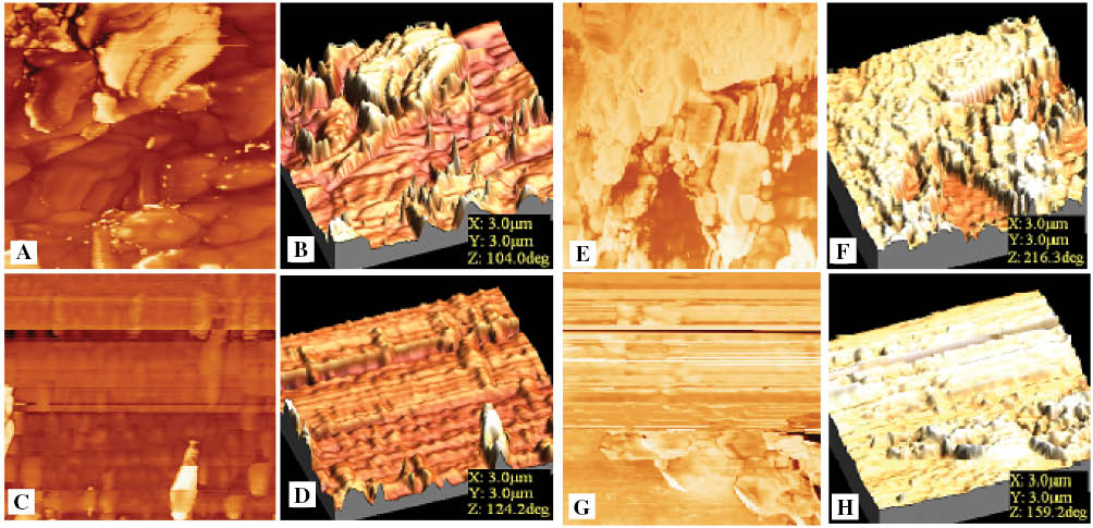
Tapping mode AFM images of (A, B) BPA-SPAES, (C, D) cr-BPA-SPAES-11 and (E, F) 6F-SPAES (G, H) cr-6F-SPAES-11 membranes, respectively.
3.8 XRD studies
Figure 8 showed the XRD diffractograms of the BPA-SPAES and its crosslinked cr-BPA-SPAES membranes and similar results were obtained for 6F-SPAES and its crosslinked membranes. It was observed that both the pristine membranes BPA-SPAES and 6F-SPAES displayed a sharp diffraction peak at 2θ=26°and 24°, respectively, which was shifted to lower angles in the case of crosslinked membranes and broadened as the ratio of EFN increased. The broadening of the diffraction peak indicated that the crosslinked membranes are largely amorphous with low crystallinity. The crosslinking involves the interactions of the polymeric chains of the pristine membranes BPA-SPAES and 6F-SPAES with the EFN. These interactions distort the membrane morphology, leading to a long-term disturbance between the polymeric chains. Thus crosslinking reduces the ordered arrangement of the membranes.
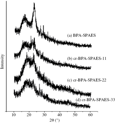
XRD graphs of BPA-SPAES and its crosslinked cr-BPA-SPAES membranes.
3.9 Mechanical properties
The mechanical stability of the membranes is one of the decisive parameters in determining the performance of the membranes in addition to high proton conductivity for fuel cell applications. The membranes should possess adequate toughness and elasticity so as to withstand the fabrication of the membrane electrode assembly and its operation in the fuel cell. The introduction of epoxy resin within the main framework of the membrane was professed to increase the mechanical properties of the membrane as the aromatic groups could provide toughness to the membrane and the ether linkage present in the epoxy resin would introduce flexibility. The mechanical properties are summarized in Table 2. From the results it can be observed that the pristine BPA-SPAES membrane showed a tensile strength of 59.09 MPa, Young’s modulus of 84.26 MPa and elongation at break of 114.87%, respectively. After crosslinking with EFN the tensile strength, Young’s modulus and elongation at break increased to 87.73 MPa, 185.77 MPa and 173.03%, respectively, for the cr-BPA-SPAES-11 membrane. However, as the content of epoxy resin was increased the tensile strength, Young’s modulus and elongation at break decreased for the cr-BPA-SPAES-22 and cr-BPA-SPAES-33 membranes compared with cr-BPA-SPAES-11 membrane. But all the cr-BPA-SPAES membranes showed a better mechanical performance than that of the pristine BPA-SPAES membrane. However, it was interesting to note that the membrane of 6F-SPAES was difficult to cast into a definite shape due to the brittleness of the copolymer, but on crosslinking the copolymer with EFN in a 11% weight ratio of EFN to 6F-SPAES using the set procedure, a membrane with tensile strength of 39.80 MPa, Young’s modulus of 37.69 MPa and elongation at break of 163.44% was obtained. The cr-6F-SPAES-22 and cr-6F-SPAES-33 membranes showed a reduction in the tensile strength, Young’s modulus and elongation at break. The trend is found to be the same as the one shown by cr-BPA-SPAES membranes.
It can be concluded from the results that the crosslinking of both the copolymers with EFN in a 11% ratio is found to be good for increasing the toughness and ductility of the membranes simultaneously. The lower water uptake by the crosslinked membranes indicated that crosslinking could be an efficient method in order to provide dimensional stability to the membranes. The results proved that these membranes were found to be tough and ductile enough for their potential use as PEM materials and would satisfy the demand of PEMFCs.
3.10 Thermal properties
Thermal stability of the PEMs becemes significant for the durability during fuel cell operation at elevated temperature and was evaluated using TGA technique. The results are presented in Table 3 and TGA thermograms for BPA-SPAES and cr-BPA-SPAES membranes are shown in Figure 9. It was observed that the membranes displayed a three step weight loss. The weight losses in the temperature range of 25–100°C was due to the evaporation of hydrated water. Pristine membranes exhibited a lower weight loss in this region due to high water uptake in comparison to crosslinked membranes. The water molecules seem to be bounded directly to the carboxylic acid and sulfonic acid groups via hydrogen bonds. The weight loss in the region of 200–350°C was attributed to the loss of sulfonic acid groups. The polymer further went through a thermal degradation at temperatures >400°C which corresponded to the decomposition of the main chain of the polymer. Hence the results of TGA confirmed that crosslinking can be an important parameter for the enhancement of the thermal stability of the membranes and this treatment makes the membranes suitable for high temperature operating fuel cell applications.
Thermal behavior description by TGA and DSC.
| Membranes | Weight loss (%) below 250°C | Char residue (%) at 600°C | LOI | Tg (°C) | Tm(°C) |
|---|---|---|---|---|---|
| BPA-SPAES | 13.43 | 45.80 | 35.82 | 132 | 218 |
| cr-BPA-SPAES-11 | 6.91 | 51.57 | 38.12 | 160 | 240 |
| cr-BPA-SPAES-22 | 11.87 | 44.56 | 35.32 | 195 | – |
| cr-BPA-SPAES-33 | 8.18 | 34.77 | 31.40 | 192 | 230 |
| 6F-SPAES | 21.61 | 39.03 | 33.11 | 160 | 233 |
| cr-6F-SPAES-11 | 7.47 | 52.07 | 38.32 | 180 | 250 |
| cr-6F-SPAES-22 | 6.02 | 36.54 | 32.11 | 230 | 260 |
| cr-6F-SPAES-33 | 3.40 | 24.54 | 27.31 | 200 | – |
| Nafion | 1.84–5.42a | – | – | 145b,c | 230b,c |
a[44], b,c[ 45, 46].
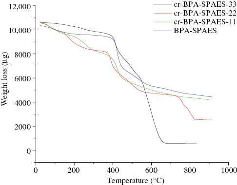
TGA graphs of BPA-SPAES and its crosslinked cr-BPA-SPAES membranes.
The limiting oxygen index (LOI) value was calculated by using Krevelen’s equation [47] in order to confirm the flame retardancy of the synthesized membranes. All the membranes had LOI values >27 and cr-BPA-SPAES-11 and cr-6F-SPAES-11 membranes showed a better flame resistance behavior.
3.10.1 DSC
Figure 10 shows the DSC scans for the 6F-SPAES and cr-6F-SPAES membranes. The glass transition temperatures (Tg) as well the melting temperatures (Tm) of the membranes have been summarized in Table 3. The Tg of a polymer is the temperature at which the polymeric chain segments in the amorphous regions of the polymer attain sufficient heat energy to move in a coordinated manner. The Tg of the BPA-SPAES and its crosslinked cr-BPA-SPAES membranes was observed in the region between 132 and 195°C and Tm in the range of 218–240°C. The Tg and Tm for the 6F-SPAES and its crosslinked cr-6F-SPAES membranes were observed in the ranges of 160–230°C and 233–260°C, respectively. The results reveal that the Tg and Tm for the crosslinked membranes are higher than their corresponding pristine membranes. It was also observed that Tg and Tmfor all the 6F-SPAES membranes were higher than the corresponding BPA-SPAES membranes. This was probably due to the presence of thermally stable CF3 groups in the main chain of the 6F-SPAES copolymer. The cr-BPA-SPAES-22, cr-BPA-SPAES-33 and cr-6F-SPAES-33 membranes did not show a distinct Tm due to an increase in the intermolecular interactions with the increase in the amount of epoxy resin, which would reduce the molecular mobility among the polymeric chains. It can be concluded that crosslinked membranes synthesized in our present work showed improved thermal properties which were high enough to enable their use as PEMs in fuel cell applications.
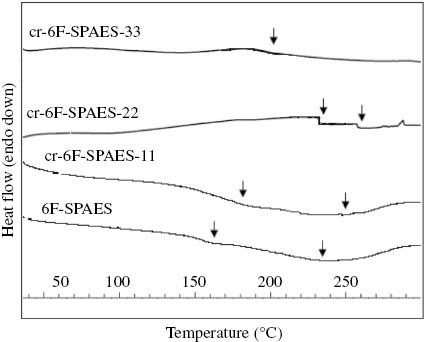
DSC scans of the 6F-SPAES and its crosslinked cr-6F-SPAES membranes.
4. Conclusions
A new series of SPAES have been synthesized. The properties of the membranes before and after crosslinking reaction were evaluated. XRD studies showed a decrease in the crystalline nature of the crosslinked membranes. It was observed that crosslinking treatment effectively caused a significant increase in oxidative stability, mechanical strength and thermal stability, but simultaneously led to a reduction in water uptake, IEC and proton conductivity of the crosslinked membranes. The reduction in water uptake, IEC and proton conductivity was also confirmed by the reduction of the ionic channels in the case of the crosslinked membranes, as identified by AFM technique. Therefore, crosslinking treatment was found to be a suitable method for balancing the high proton conductivity due to excessive water uptake and the low dimensional stability of the membranes. The crosslinking had resulted in an enhancement in tensile strength and elongation at break and thus had contributed towards the increase in toughness and elasticity of the membranes. The membranes were found to have adequate thermal stability for high temperature fuel cell applications. The synthesized SPAES membranes showed the decomposition of the sulfonic acid groups in the range of 200–350°C which is comparable to the Nafion membrane. Similar to the Nafion membrane, the degradation of the synthesized SPAES membranes occurred above 400°C [44]. It has also been concluded that a higher degree of crosslinking had an adverse effect on the proton conductivity of the synthesized membranes. The membranes prepared with a 11% weight ratio of EFN were found to possess the requisite properties such as optimum IEC, proton conductivity, low water and methanol uptake and high oxidative stability and mechanical strength that are desired in a PEM.
About the authors

Vaishnav Kiran received her Bachelor’s degree in 2001 from Punjab University Chandigarh, India and her Master’s degree in 2003 from GNDU Amritsar, India. She is currently pursuing her PhD degree at the National Institute of Technology Hamirpur H.P., India, on the subject of the synthesis of proton exchange membranes, for proton exchange membrane fuel cells. Her research interests include polymer chemistry and the emerging area of non-conventional energy sources like microbial fuel cells, etc. She has six publications in international and national journals, and has presented at various conferences.

Bharti Gaur is an Associate Professor in the Department of Chemistry, at the National Institute of Technology (NIT) Hamirpur, Himachal Pradesh, India. She received her BSc degree in 1986 from St. Bedes College Shimla, India. She did her post-graduation studies in Organic Chemistry at Sardar Patel University, Anand, Gujarat, India, in 1988. She obtained her PhD degree from HBTI Kanpur, India, in 1993. She taught in a number of undergraduate and postgraduate institutes before joining the NIT Hamirpur as Assistant Professor in 2010. She has more than 25 research papers in international journals and conferences and has filed two patents in the field of energetic binders for solid rocket propellants. Her current research interests include microbial fuel cells, the synthesis of proton exchange membrane for fuel cells, nanocomposites, the synthesis of adhesives, and coatings.
References
[1] Kiran V, Gaur B. Rev. Chem. Eng. 2013, 29, 189–203.Search in Google Scholar
[2] Wang L, Wang D, Zhu G, Li J. Eur. Polym. J. 2011, 47, 1985–1993.Search in Google Scholar
[3] Zhao Y, Yin J. J. Membr. Sci. 2010, 351, 28–35.Search in Google Scholar
[4] Mohanty AK, Mistri EA, Ghosh A, Banerjee S. J. Membr. Sci. 2012, 409–410; 145–155.10.1016/j.memsci.2012.03.048Search in Google Scholar
[5] Bhadra S, Kim NH, Lee JH. J. Membr. Sci. 2010, 349, 304–311.Search in Google Scholar
[6] Swier S, Chun YS, Gassa J, Shaw MT, Weiss RA. Polym. Eng. Sci. 2005, 45, 1081–1090.Search in Google Scholar
[7] Wu HL, Ma CM, Liu FY, Chen CY, Lee SJ, Chian CL. Euro. Polym. J. 2006, 42, 1688–1695.Search in Google Scholar
[8] Matsumoto K, Higashihara T, Ueda M. J. Polym. Sci., Part A: Polym. Chem. 2009, 47, 3444–3453.Search in Google Scholar
[9] Li D, Li Z, Hu F, Long S, Zhang G, Yang J. Polym. Eng. Sci. 2013, 54, 2013–2022.Search in Google Scholar
[10] Mabrouk W, Ogier L, Vidal S, Sollogoub C, Matoussi F, Fauvarque JF. J. Membr. Sci. 2014, 452, 263–270.Search in Google Scholar
[11] Wiles KB, Diego CM, Abajo JD, McGrath JE. J. Membr. Sci. 2007, 294, 22–29.Search in Google Scholar
[12] Guo M, Liu B, Guan S, Li L, Liu C, Zhang Y, Jiang Z. J. Power Sources. 2010, 195, 4613–4621.Search in Google Scholar
[13] Sankir M, Kim YS, Pivovar BS, McGrath JE. J. Membr. Sci. 2007, 299, 8–18.Search in Google Scholar
[14] Gao Y, Robertson GP, Guiver MD, Jian X, Mikhailenko SD, Wang K, Kaliaguine S. J. Polym. Sci., Part A: Polym. Chem. 2003, 41, 2731–2742.Search in Google Scholar
[15] Chen YL, Meng YZ, Hay AS. Macromolecules 2005, 38, 3564–3566.10.1021/ma047591oSearch in Google Scholar
[16] Endo N, Matsuda K, Yaguchi K, Hu Z, Chen K, Higa M, Okamoto K. J. Electrochem. Soc. 2009, 156, 628–633.Search in Google Scholar
[17] Gong C, Luo Q, Li Y, Giotto M, Cipollini NE, Yang Z, Weiss RA, Scola DA. J. Polym. Sci., Part A: Polym. Chem. 2011, 49, 4476–4491.Search in Google Scholar
[18] Yu DM, Yoon S, Kim TH, Lee JY, Lee J, Hong YT. Macromol. Resh. 2014, 22, 79–84.Search in Google Scholar
[19] Li Q, Jensen JO. In Membranes for Energy Conversion, Peinemann KV, Nunes SP, Eds., Wile-VCH, Verlag: Weinheim Germany, 2007, Vol. 2, p 61.Search in Google Scholar
[20] Qi Y, Gao Y, Tian S, Hill AR, Gaudet J, Guay D, Hay AS. J. Polym. Sci., Part A: Polym. Chem. 2009, 47, 1920–1929.Search in Google Scholar
[21] Han M, Zhang G, Li M, Wang S, Liu Z, Li H, Zhang Y, Xu D, Wang J, Ni J, Na H. J. Power Sources 2011, 196, 9916–9923.10.1016/j.jpowsour.2011.08.049Search in Google Scholar
[22] Aili D, Cleemann LN, Li Q, Jensen JO, Christensen E, Bjerrum NJ. J. Mater. Chem. 2012, 22, 5444–5453.Search in Google Scholar
[23] Li Q, Pan C, Jensen JO, Noye P, Bjerrum NJ. Chem. Mater. 2007, 19, 350–352.Search in Google Scholar
[24] Yu DM, Sung IH, Yoon YJ, Kim TH, Lee JY, Hong YT. Fuel Cells 2013, 13, 843–850.Search in Google Scholar
[25] Feng MN, Pu ZJ, Zheng PL, Jia K, Liu XB. RSC Adv. 2015, 5, 34372–34376.Search in Google Scholar
[26] Kim T, Choi YW, Kim CS, Yang TH, Kim MN. J. Mater. Chem. 2011, 21, 7612–7621.Search in Google Scholar
[27] Wona JH, Lee HJ, Yoon KS, Hong YT, Lee SY. Int. J. Hydrogen Energ. 2012, 37, 9202–9211.Search in Google Scholar
[28] Sonpingkam S, Pattavarakorn D. Int. J. Chem. Eng. Appl. 2014, 5, 181–185.Search in Google Scholar
[29] Harrison WL, Wang F, Jeffery B, Mecham JB, Bhanu VA, Hill M, Kim YS, Mcgrath JE. J. Polym. Sci., Part A: Polym. Chem. 2003, 41, 2264–2276.Search in Google Scholar
[30] William Harrison 2002. Dr. Godson C. Nwokogu, Hampton University, Va Blacksburg, Virginia, USA.Search in Google Scholar
[31] Ding FC, Wang SJ, Xiao M, Meng YZ. J. Power Sources 2007, 164, 488–495.10.1016/j.jpowsour.2006.11.028Search in Google Scholar
[32] Smitha B, Sridhar S, Khan AA. J. Membr. Sci. 2005, 259, 10–26.Search in Google Scholar
[33] Miyatake K, Watanabe M, Li Q, Jensen JO. In Membranes for Energy Conversion, Peinemann KV, Nunes SP, Eds., Wile-VCH Verlag: Weinheim Germany, 2007, Vol. 2, p 56–74.Search in Google Scholar
[34] Sahu AK, Pitchumani S, Sridhar P, Shukla AK. Bull. Mater. Sci. 2009, 32, 285–294.Search in Google Scholar
[35] Hsu W, Gierke TD. J. Membr. Sci. 1983, 13, 307–326.Search in Google Scholar
[36] Agmon N. Chem. Phys. Lett. 1995, 244, 456–462.Search in Google Scholar
[37] Moilanen DE, Spry DB, Fayer MD. Langmuir 2008, 24, 3690–3698.10.1021/la703358aSearch in Google Scholar
[38] Zhang X, Hu Z, Zhang S, Chen S, Chen S, Liu J, Wang L. J. Appl. Polym. Sci. 2011, 121, 1707–1716.Search in Google Scholar
[39] Nakagawa T, Nakabayashi K, Higashihara T, Ueda M. J. Polymer Sci., Part A: Polym. Chem. 2011, 49, 2997–3003.Search in Google Scholar
[40] Lee KH, Chu JY, Kim AR, Nahm KS, Yoo DJ. Bull. Kor. Chem. Soc. 2013, 34, 1763–1770.Search in Google Scholar
[41] Almeida JRM, Menezesb GW, Monteirob SN. Mater. Res. 2003, 6, 415–420.Search in Google Scholar
[42] Kishi A, Umeda M. J. Appl. Polym. Sci. 2009, 114, 3343–3350.Search in Google Scholar
[43] Vona MLD, Sgreccia E, Tamilvanan M, Khadhraoui M, Chassigneux C, Knauth P. J. Membr. Sci. 2010, 354, 134–141.Search in Google Scholar
[44] Ma CH, Yu TL, Lin HL, Huang YT, Chen YL, Jeng US, Lai YH, Sun YS. Polymer 2009, 50 1764–1777.10.1016/j.polymer.2009.01.060Search in Google Scholar
[45] Almeida SH, Kawano Y. J. Therm. Anal. Calorim. 1999, 58, 569–577.Search in Google Scholar
[46] Stefanithis ID, Mauritz KA. Macromolecules 1990, 23, 2397–2402.10.1021/ma00210a043Search in Google Scholar
[47] Van Krevelen DW. Polymer 1975, 16, 615–620.10.1016/0032-3861(75)90157-3Search in Google Scholar
©2015 by De Gruyter
This article is distributed under the terms of the Creative Commons Attribution Non-Commercial License, which permits unrestricted non-commercial use, distribution, and reproduction in any medium, provided the original work is properly cited.
Articles in the same Issue
- Frontmatter
- In this issue
- Editorial
- Electrification of chemistry – what is the synergy between plasma synthesis and chemical plant modularization?
- Original articles
- Optimization of biodiesel synthesis under simultaneous ultrasound-microwave irradiation using response surface methodology (RSM)
- The synthesis of optically enriched 2-benzyl- 3-nitropropionic amide
- Cobalt, nitrogen-codoped carbon quantum dots as a synergistic catalyst for oxygen reduction reaction
- Sulfonated poly (arylene ether sulfone) proton exchange membranes for fuel cell applications
- Preparation of high surface area activated carbon from Eupatorium adenophorum using K2CO3 activation by microwave heating
- An environmental procedure to extract titanium components and metallic iron from Ti-bearing blast furnace slag
- Recovery of molybdenum from alkali leaching solution of low-grade molybdenum concentrate by ion exchange
- Impacts of ultrasound on leaching recovery of zinc from low grade zinc oxide ore
- Study on the calcination experiments of rare earth carbonates using microwave heating
- Conference announcement
- Conferences 2015–2017