Research on simulation testing of humidity-controlled salt spray corrosion environment for electrical products under working conditions
-
Chuan Chen

 ,
Li Xiang
,
Li Xiang

Abstract
Traditional neutral salt spray tests fail to accurately simulate the accelerated corrosion that occurs under actual energized conditions. We have developed a salt spray test chamber capable of reducing the relative humidity (RH) in the testing environment to prevent short circuits, insulation failures, and other faults that lead to premature damage during testing. Initially, the effect of salt spray concentration on corrosion at 85 % RH was examined, and it was found that the corrosion rate does not increase when the concentration surpasses 50 mg/m3. The humidity-controllable salt spray test demonstrated a closer match to real environmental corrosion, judging by both the appearance of corrosion and the acceleration ratios across different metals, where the acceleration ratio difference between maximum and minimum values was reduced from 18.6 times to 1.4 times. The influence of RH on the corrosion rate was revealed, with the highest rate observed at 75 % RH. Lastly, we proposed optimal parameters for energized salt spray tests, evaluated the failure modes of several products under these tests, preliminarily confirmed the consistency and acceleration effects of this method for electrical products in real marine atmospheric conditions.
1 Introduction
In marine atmospheric environments, the failure rate of electrical products is twice that of similar products in inland regions. Approximately 73 % of these failures are attributed to corrosion and aging (Luo et al. 2016; Xiang et al. 2022). Thus, enhancing the environmental adaptability of these products in marine conditions is crucial. The neutral salt spray test is a commonly employed method for evaluating the corrosion resistance of metal materials (Sun et al. 2021). The corrosiveness verification of coating materials and metal materials has preliminarily demonstrated the correlation between this experimental method and the actual environment (Schmid 2024). Current salt spray test chambers use compressed air to atomize the solution into a fine mist, which is then introduced into the test chamber. This process results in a salt spray with high concentration and relative humidity (RH), often exceeding actual environmental conditions, and consequently accelerates the corrosion of metal materials. However, this accelerated corrosion test is unsuitable for electrical and electronic products in marine environments, due to most acceleration equipment only considers environmental factors, ignoring the impact of electrical products' operational states on corrosion. Additionally, the humidity during the neutral salt test conditions approaches 100 %, and the salt spray concentration is several hundred times greater than that of the actual environment, leading to significant discrepancies of service conditions (Chen et al. 2025) and mechanism of corrosion (Alfattani et al. 2021). Then, it is difficult to provide data support for dynamic design.
Consequently, relying on the results from the existing neutral salt spray chamber to assess the environmental adaptability of the equipment may not be meaningful (Rudomilova et al. 2020; Wang et al. 2020).
The purpose of conducting salt spray tests is to measure the product’s resistance to salt spray corrosion and its service life in marine atmospheric enviroments. If there is no current and voltage applied during the testing process, the corrosion mechanism of electrical and electronic products will deviate greatly from the actual situation. The principal challenge in conducting salt spray simulation tests for electronic and electrical products is the control of RH during the test. Therefore, we attempt to reduce the RH in the neutral salt spray test chamber to achieve long-term simulation of the salt spray corrosion environment under the effects of current and voltage on the product.
2 Design of a salt spray test chamber with controllable relative humidity
The U.S. and Chinese militaries have developed salt spray generation devices using atomizing spray systems for aircraft engine testing. The atomizing method facilitates more precise control and adjustment of salt spray concentration. Aspirating sampling spectroscopy provides accurate measurement of salt spray concentration in the testing environment (Liu et al. 2025).
To develop a salt spray test chamber suitable for electrical and electronic products, which replicates the RH of actual conditions, a system was designed. In this system, the generated mixed salt spray is delivered to an air conditioning module via a salt spray generation module. The air conditioning module adjusts the temperature and humidity of the mixed salt spray before it flows into the test chamber. This setup creates a controlled testing environment with regulated temperature, humidity, and salt spray concentration.
As depicted in Figure 1, we produce salt spray gas with predetermined RH and concentration by mixing and adjusting air and salt spray gas. Parameters for both air and salt spray gas prior to mixing – including volume, RH, temperature, and salt spray concentration – are established based on the target RH and salt spray concentration after mixing. The determination is founded on the principle that the water and salt content in the gas remains constant before and after mixing. The specific formula is provided below:
C is the salt spray concentration to be controlled within the test chamber; C1 is the NaCl concentration in the salt spray atmosphere before mixing, measured in g/m3; ω1 is the mass fraction of NaCl in the droplets in the salt spray atmosphere before mixing; V1 is the volume of the salt spray atmosphere before mixing; RH1 is the RH of the salt spray atmosphere before mixing; S1 is the saturated absolute humidity of the salt spray atmosphere before mixing, dependent on temperature and measured in g/m3; V2 is the volume of the humid air before mixing; RH2 is the RH of the humid air before mixing; S2 is the saturated absolute humidity of the humid air before mixing, temperature-dependent and measured in g/m3; ω2 is the mass fraction of NaCl in the droplets in the salt spray atmosphere after mixing; RH is the RH after mixing, and S represents the saturated absolute humidity of the mixed air before mixing, also temperature-dependent and measured in g/m3.
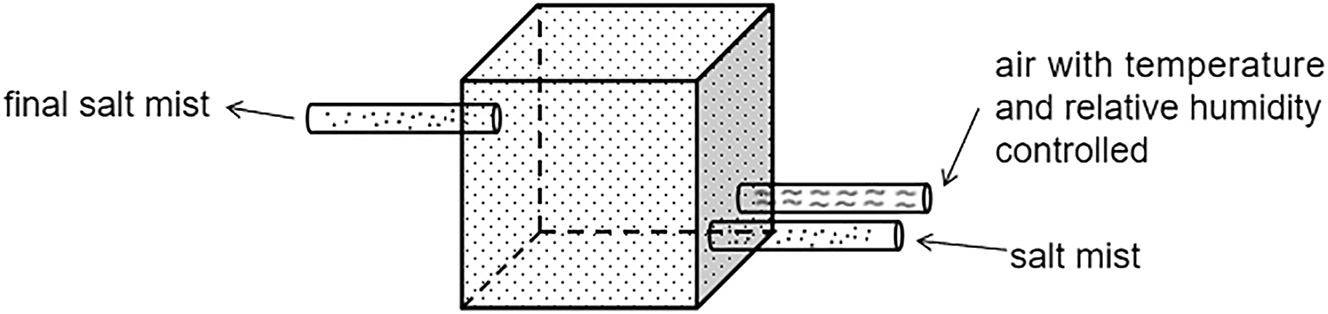
Schematic diagram of the mixing process of salt mist and air.
The formula assumes that both gas streams have equal temperature and pressure before mixing, and the total volume is the sum of their initial volumes. Further derivation of the formula yields:
Let
By using the above formulas 3 and 5, and based on the experimental parameter requirements, the various parameters before mixing can be determined.
The principles of balancing salinity and moisture content before and after mixing have been used to derive theoretical formulas for various parameters. These formulas enable the determination of the necessary salt mist concentration and RH for experiments by controlling factors such as the volume, RH, and temperature of both the salt mist atmosphere and the humid air. Figure 2 illustrates a potential design of a salt mist chamber.
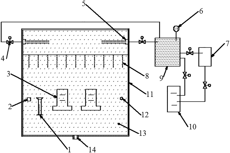
Example of test apparatus for humidity-controlled salt mist test. 1, collecting device; 2, measuring of salt mist concentration; 3, test specimen; 4, flow valve; 5, salt aerosol inlet; 6, pressure gauge; 7, air temperature and relative humidity control devices; 8, falling down salt aerosol; 9, mixing chamber; 10, salt mist generation device; 11, test chamber; 12, temperature and humidity control devices; 13, salt aerosol; 14, outlet port connected to exhaust air treatment unit.
In the testing chamber, air circulates at a velocity of less than 1 m/s. Traditionally, control of the salt spray testing chamber was achieved through sedimentation parameters. This method has now been superseded by directly monitoring and controlling the concentration of salt spray to maintain a stable environment within the chamber. The primary challenge of this equipment is effectively managing the concentration of salt spray aerosols (Moon 2018). The primary challenge for the equipment is the control of salt spray aerosol concentrations. To monitor the salt spray, the test chamber employs a 10-min gas absorption process and utilizes differences in Raman spectral peak shifts of various sodium chloride solutions to accurately determine gas concentration, thereby ensuring stability in the salt spray concentration (Mernagh and Wilde 1989). The system uses 10 ml of water as the absorbing liquid for the aerosols and employs a 532 nm, 100 W laser for the continuous irradiation of this liquid. Testing revealed Raman peak shifts at varying liquid concentrations, as depicted in Figure 3, with the peak at 3,468 cm−1 selected as a characteristic value. In addition, a curve illustrating the relationship between concentration and peak value was established, as shown in Figure 4. The peak size must be mapped to the analog signal simulation model for display transmission. There is a good linear relationship between peak intensity and salt spray concentration.
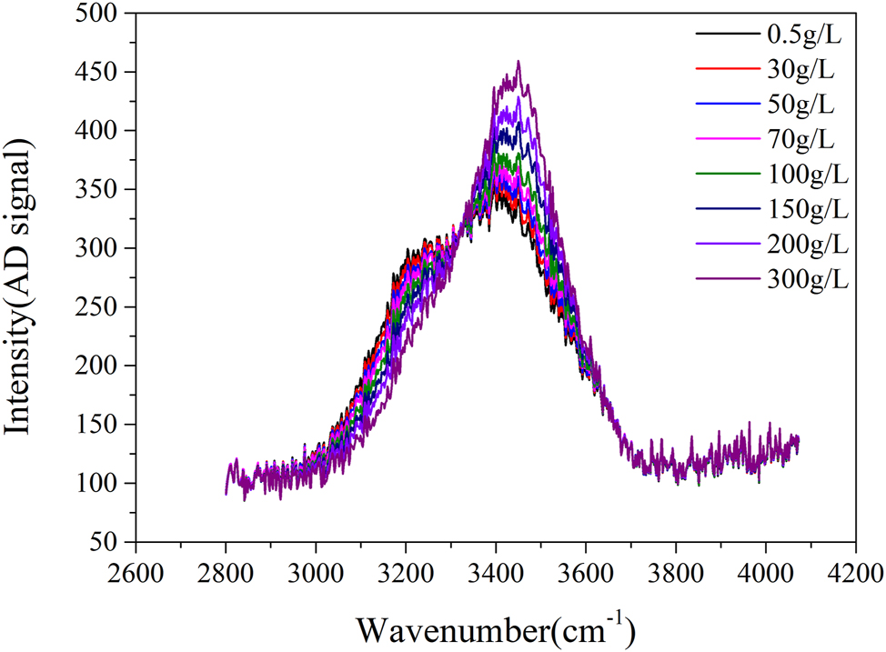
Raman shift peak curves for various concentrations of sodium chloride solutions.
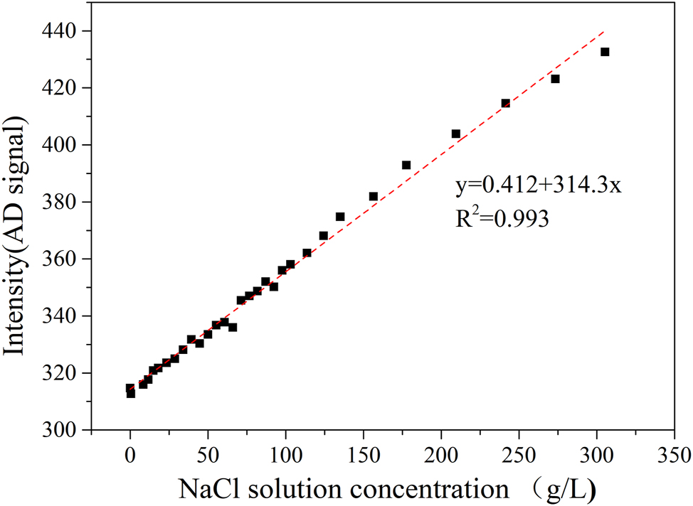
Linear relationship between sodium chloride solution concentration and Raman shift peak.
3 Impact of reduced humidity on the corrosion of metal materials
3.1 Effect of salt spray concentration on corrosion rate at 85 % relative humidity
Within the neutral salt spray testing chamber, the chloride ion concentration is measured by aspirating specimens at a rate of 0.6 L/min, followed by spectrophotometric analysis. The salt spray concentration within the test chamber is approximately 100 mg/m3. Dry plate method (International Organization for Standardization. ISO 9225 2012), applied over two days, reveals that salt spray deposition at various locations within the chamber ranges from 500 to 1,000 mg/m2·d, highlighting a significant issue of uneven deposition traditionally observed in these chambers. The deposition concentration remains around 100 mg/m3, ensuring that the airborne chloride ion concentration is consistent with levels found in conventional neutral salt spray tests. The test environment’s humidity has been adjusted to align with the RH of actual oceanic conditions, approximately 85 % RH. An amount of 5 % sodium chloride solution, identical to that used in neutral salt spray tests, was employed. An ultrasonic atomization device was used to modify the salt spray concentration in the environment. Carbon steel served as a material to evaluate the corrosion rate under varying salt spray concentrations. After 48 h of exposure, the surface appearance is depicted in Figure 5, and Figure 6 illustrates the correlation between corrosion weight loss and differing salt spray concentrations by the weightlessness method. The salt spray concentration peaks at approximately 50 mg. Beyond this point, further increases in concentration do not elevate the corrosion rate; instead, there is a slight decrease. At this stage, the salt spray deposition ranges from 30 to 50 mg/m2·d, closely resembling the deposition levels found in actual marine atmospheric environments (Chen et al. 2013).
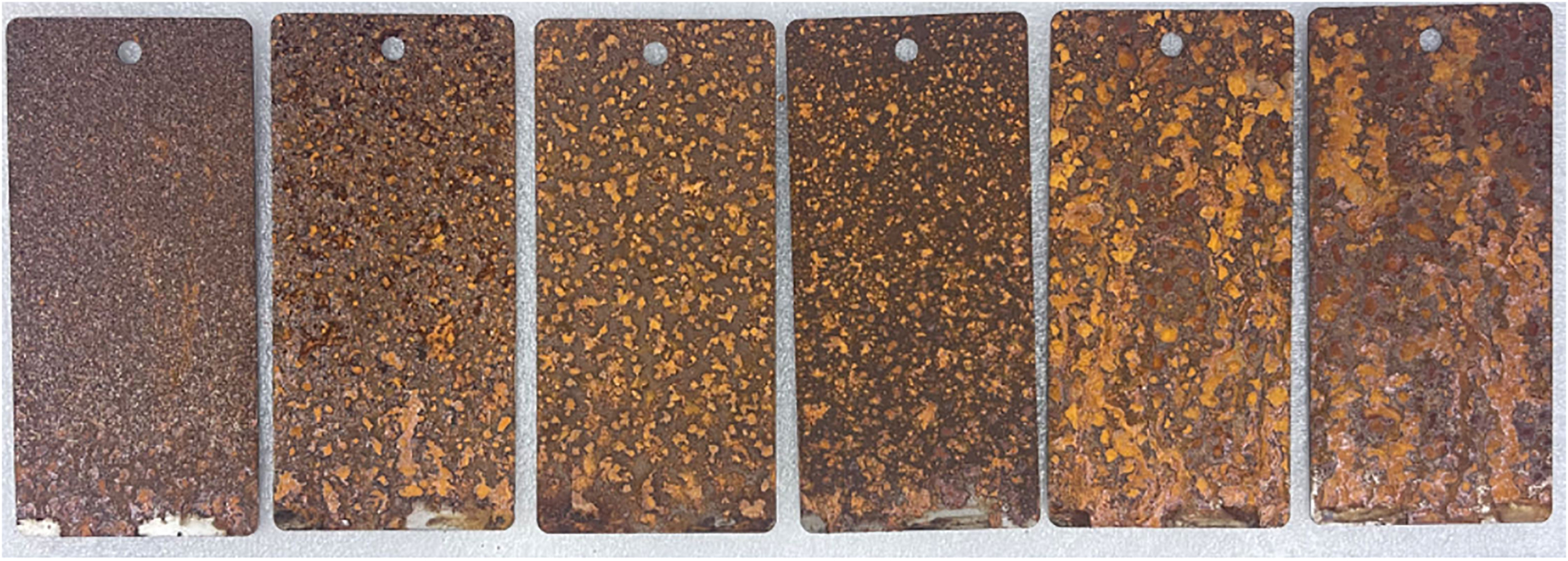
Morphology of carbon steel corrosion under varying salt spray concentrations (35 °C, 85 %). From left to right: 30 mg/m3; 50 mg/m3; 75 mg/m3; 100 mg/m3; 120 mg/m3; 150 mg/m3.
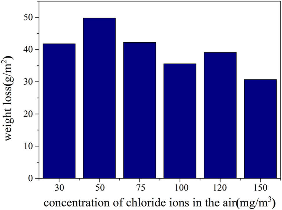
Weight loss of carbon steel due to corrosion under varying salt spray concentrations (35 °C, 85 %).
3.2 Comparison of various metal materials in different salt spray environments
In further validation experiments, we selected five commonly used metals in electrical products: carbon steel, pure copper, pure silver, pure aluminum, and pure nickel. These materials were tested for 72 h using both humidity-controlled and neutral salt spray tests, and the results were compared with those from an outdoor experiment conducted 100 m from the coast in Lingao, Hainan, China.
The differences in metal corrosion rates among the experimental method, the neutral salt spray test, and the field test are illustrated in the specimen photos taken after 72 h, as shown in Figure 7, Ag and Ni corrosion is relatively mild, so corrosion morphology images are not included. Figure 8 presents the difference in corrosion rates between the neutral salt spray test and the humidity-controlled salt spray test. The corrosion morphology photographs reveal that in low-humidity environments, salt spray adheres to the surface of the specimens without spreading, leading primarily to pitting and block corrosion, which better reflects actual usage scenarios of the materials. We found that compared to the neutral salt spray test, the corrosion of copper and silver was more severe in the reduced-humidity salt spray test. The corrosion rate of copper was approximately 6.6 times greater than in the neutral salt spray test, while for silver, it was about 3.6 times greater. Due to the light corrosion of silver specimens, the corrosion rate was determined by measuring corrosion potential and current using the electrochemical reduction method, as outlined in ANSI/ISA-71.04 (The International Society of Automation. ANSI/ISA-71.04 2013) and ASTM B825 standards(American Society of Testing and Materials, ASTM B825 2019). Since most electrical and electronic products utilize copper and silver for their superior conductivity in components, wires, and circuit boards, the humidity-controlled salt spray test not only allows for reduced-humidity testing of electrical products but also results in a higher corrosion rate compared to traditional neutral salt spray tests.
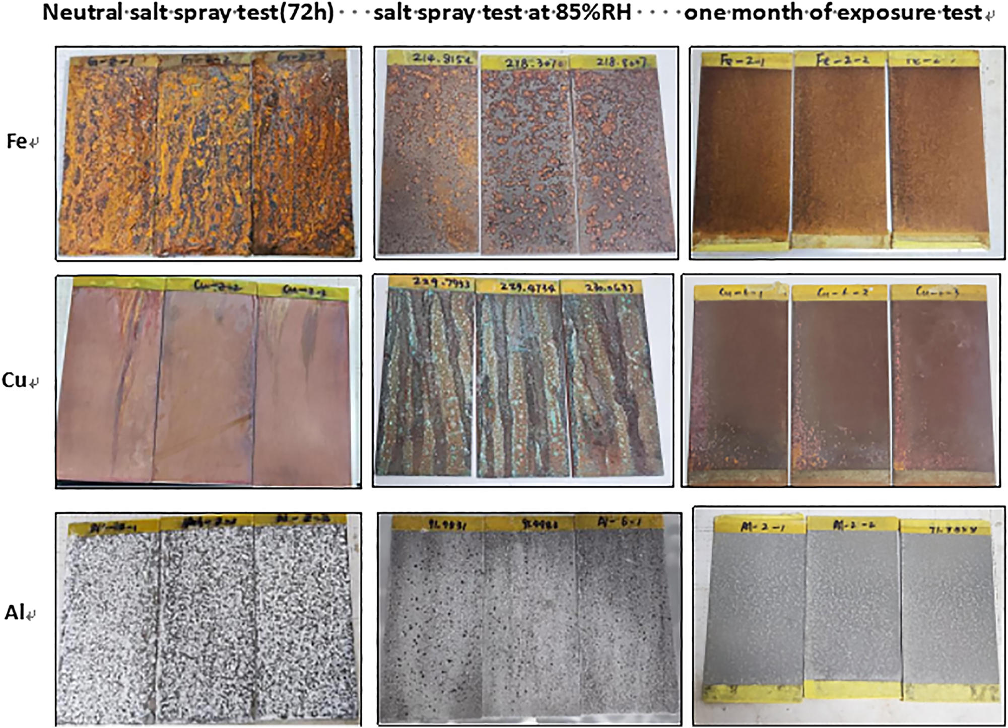
Corrosion morphology of three metals after the neutral salt spray test, the salt spray test at 85 % relative humidity, and one month of exposure under an outdoor shelter.
Variation in metal corrosion rates after 72 h of neutral salt spray testing and humidity-controlled salt spray testing.
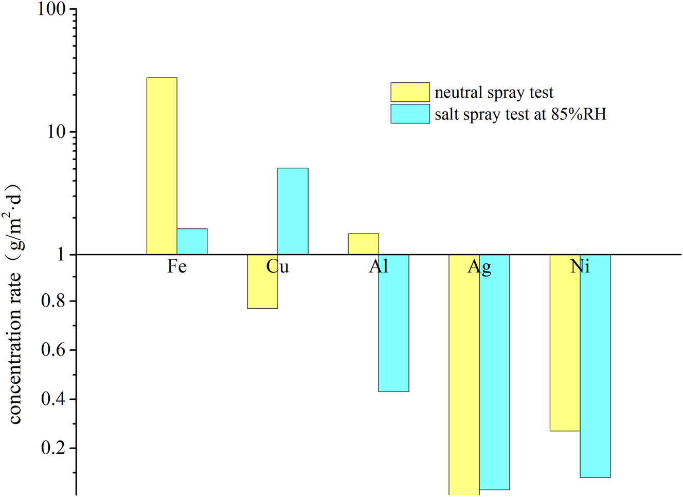
Figure 9 illustrates the corrosion acceleration factors of different metals in both neutral and humidity-controlled salt spray tests, using the Lingao coastal test site in Hainan, China, as a benchmark. It is evident that the acceleration factor for metals such as carbon steel and aluminum in neutral salt spray tests exceeds 50, whereas for copper and silver, it is only a few times, with a discrepancy exceeding 20 times. This distortion in corrosion acceleration for electrical and electronic products is significant, but in the humidity-controlled salt spray test, the difference is reduced to within a factor of five. Excluding carbon steel, which is not commonly used in electrical products, the discrepancy can be controlled within a factor of two, providing a more accurate acceleration effect for these products.
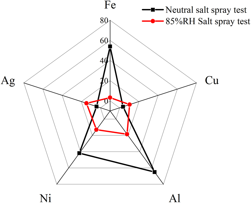
Comparison of corrosion acceleration rates for different metal materials in neutral salt spray testing and humidity-controlled salt spray testing with actual environmental conditions.
3.3 Impact of humidity on the corrosion behavior of materials
Humidity is a major factor influencing corrosion rates. According to Tomashov’s findings from the 1940s, as the thickness of the liquid film on a metal surface increases, the corrosion rate initially rises and then falls (Tomashov 1966, 1968). This liquid film thickness is closely linked to the salt’s type and concentration, as well as the environmental humidity. In this experiment, only the environmental humidity was varied, making it the main factor affecting changes in the liquid film thickness. Previous research has shown that the deliquescence humidity of sodium chloride is approximately 75 %. Below this threshold, the salt tends to crystallize, whereas above it, the salt tends to deliquesce and hydrate. Higher humidity increases the salt’s moisture absorption, resulting in a thicker liquid film and, consequently, a more diluted electrolyte concentration for an equivalent amount of salt.
Copper and silver specimens were exposed to two-day corrosion tests in a multi-factor coupling salt spray chamber with environmental humidity levels set at 55 %, 65 %, 75 %, and 85 %. Corrosion rate changes under different humidity conditions were measured using an electrochemical reduction method.
The data in Figure 10 demonstrates that when the salt spray concentration and environmental temperature are held constant, humidity has a significant impact on corrosion. The data indicate that the corrosion film thickness of copper and silver initially increases and then decreases with rising humidity, with a turning point at 75 % humidity. This humidity level corresponds to the deliquescence point of sodium chloride, resulting in a much higher corrosion rate than at 55 % and 65 %. As humidity increases further, the concentration of salt droplets formed by deliquescence becomes more diluted, leading to a reduction in corrosion rate. Figure 5 shows that at a RH of 85 %, corrosion marks from liquid flow are evident on the surfaces of specimens inclined at a 45-degree angle. However, these marks disappear when the humidity is reduced to approximately 75 %RH.
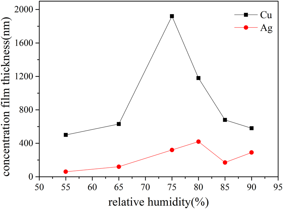
Changes in the corrosion rates of copper and silver in salt spray tests conducted under varying relative humidity conditions (35 °C).
4 Analysis of test results
4.1 The influence of variations in salt spray morphology and dynamics
Traditional neutral salt spray chambers primarily use a pneumatic injection method, which presents issues such as uneven salt spray sedimentation rates and larger droplet sizes compared to natural airborne sea salt aerosols. This leads to significant variability in test results within different locations in the chamber. The ultrasonic salt spray method utilizes high-frequency vibrations to break the solution into micron-sized droplets, thus creating a salt spray atmosphere (Xie et al. 2022). This method is characterized by high RH in the environment (RH > 90 %), and salt exists as droplets. When the ultrasonic generator and its transducer produce self-exciting oscillation, the transducer radiates strong ultrasonic waves into water, which through water and a semi-permeable membrane acts on the salt solution in the atomizing cup. This causes microbubbles (cavitation nuclei) in the salt solution to vibrate under the sound field, rapidly expanding and suddenly collapsing when sound pressure reaches a certain value. Upon collapse, the bubbles produce shock waves, a dynamic process known as acoustic cavitation. This process disperses the liquid in the gas phase and forms fine mist that continuously flows out of the atomizing cup, thus achieving ultrasonic atomization (Ardekani et al. 2019).
As shown in Figure 11, compared to the traditional neutral salt spray chamber (pneumatic injection method), the ultrasonic atomization method produces finer and more uniform salt mist droplets, whereas the droplet size in the traditional method can vary significantly, even reaching diameters of several hundred microns. This easily causes uneven distribution of salt spray within the test area and reduces the effective test area. In other words, salt mist generated by the ultrasonic atomization method enlarges the effective uniform test area or allows for a smaller test chamber with the same effective area as in the pneumatic injection method. Additionally, droplet size is related to oxygen diffusion levels; with the same hydrophilic/hydrophobic surfaces, With the thicker liquid film formed by droplet condensation, the corrosion rate increases at first and then decreases(Tomashov 1966, 1968). The primary reason lies in sediment particles forming a hygroscopic thin liquid film, allowing greater contact with oxygen and more effectively damaging existing oxide layers (Rybalka et al. 2018; Xue et al. 2019), while, As the droplets coalesce into larger droplets, larger droplets have greater thickness, increasing resistance for oxygen to reach the metal interface, and then the corrosion rate decreases (Wang et al. 2023). This is a possible cause of variability.
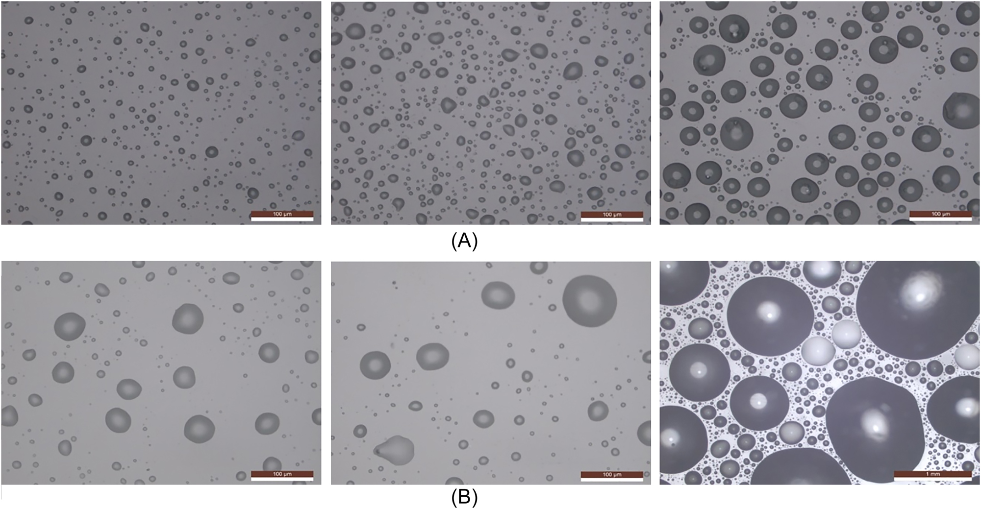
Surface morphology following 5, 10, and 60 min of salt mist droplet deposition in humidity-controlled and neutral salt spray chambers. (A) Humidity-controlled salt spray (left: 5 min; centre: 10 min; right: 60 min); (B) neutral salt spray (left: 5 min; centre: 10 min; right: 60 min).
Concurrently, the airflow within the testing chamber substantially reduces salt spray deposition, thereby more closely simulating real-world conditions. This reduction is a key factor contributing to the variations in test results.
4.2 The effects of decreased relative humidity within the testing environment
The neutral salt spray environment requires an ambient temperature of 35 °C and humidity above 85 %. Humidity inside the chamber at times reached as high as 90 %, while in the multi-factor coupling test chamber it was around 85 %. In comparison, the higher humidity in the neutral salt spray environment leads to more thorough deliquescence of salt particles, resulting in a lower concentration of the resulting salt solution. As long as the RH within a humidity-controlled salt spray testing chamber exceeds the deliquescent humidity of salts, and a thinner liquid film with a higher salt concentration forms, the promotion of anode corrosion becomes more pronounced. This process significantly damages the protective oxide films on copper and silver surfaces, manifesting as pitting or blotchy corrosion patterns. Conversely, in carbon steel, which lacks an oxide film as a protective layer, the liquid film spread over the surface reduces both the salt spray deposition and the coverage of the film, leading to a decreased corrosion rate.
5 Discussion of humidity-controlled salt spray testing of products
We conducted preliminary validations on some sensors, communication products, and control products. This experimental method is effective for identifying early failure risks in products operating in marine atmospheric environments and helps uncover design defects, guiding improvements in material selection and structural design (Leppänen et al. 2021). For instance, a newly launched electronic control programmable logic controller device showed similar wire fracture failures after 30 days in the salt spray test and one year of field operation (Figure 12). In a protection device, accelerated lab salt spray tests showed failures in 3 out of 4 parallel specimens at capacitor 4, consistent with field feedback where all failures occurred at capacitor 4 (Figure 13). Testing results for capacitors showed no failures in capacitors 1–3, and relocating capacitor 4 resolved the issue. This relies on achieving salt spray deposition and RH levels that closely resemble actual environmental conditions, thereby accelerating corrosion while preventing premature failures, such as short circuits. A higher concentration of salt spray in the atmosphere, akin to traditional high-humidity tests, does not result in short-term product failures.
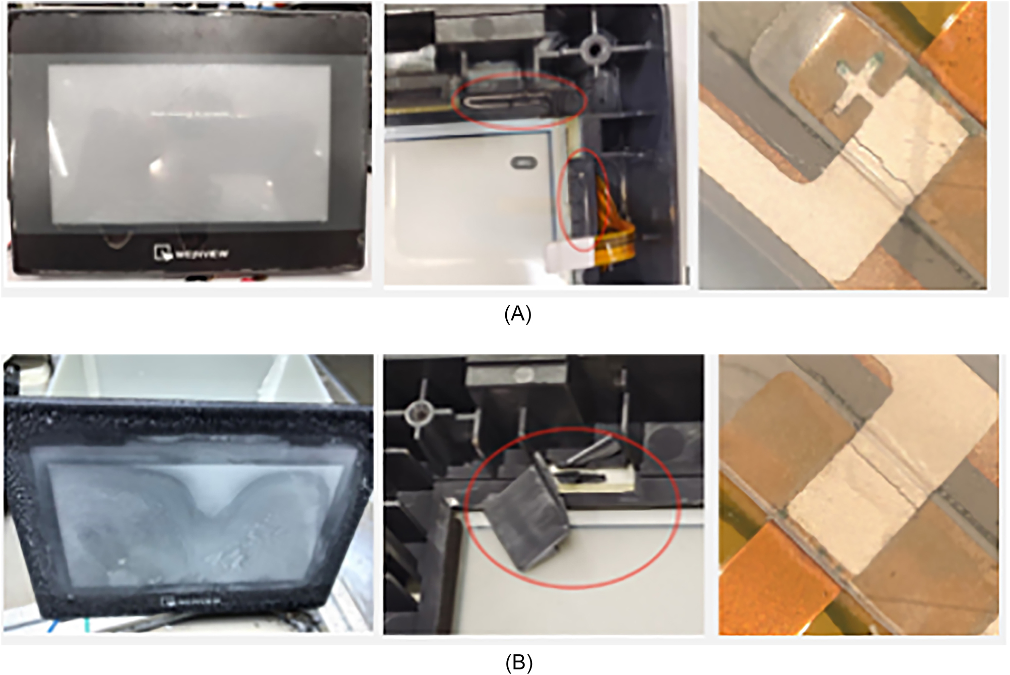
Comparison of actual failures and failures simulated in humidity-controlled salt spray tests for a specific model of charging pile control panel. (A) Actual application failure specimens; (B) specimen failed in humidity-controlled salt spray test.
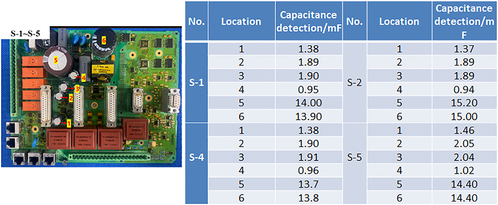
Test results of capacitor failures in a specific model of power grid protection device post-testing.
Although we have conducted initial validations with several products, more varieties of products need to undergo similar tests to accumulate relevant data and adjust salt spray concentration and design serial alternative salt spray tests as per IEC60068-2-52 (International Electrotechnical Commission, IEC 60068-2-52 2017) for different environments and product types.
Furthermore, we aim to establish a correlation between the salt spray test life of products in operation and their actual lifespan, similar to metals or anti-corrosive coatings (Wang et al. 2014). As products comprise various materials, when the corrosion rates of materials are not as severe as in traditional tests, using corrosion amounts of a typical material (e.g., Cu) can be used to establish the relationship between time in salt spray accelerated tests and actual use, which can help determine the service life of products. However, metal corrosion is also influenced by voltage, current, and electric fields, which should be considered in life estimation and prediction (Zhu et al. 2024).
6 Conclusions
This paper presents a design and development method for a humidity-controlled salt spray chamber, achieved by adding a mixing chamber in the front section of the test chamber to control humidity. By reducing relative humidity, long-term testing of electrical products can be achieved. Comparing with neutral salt spray test by the corrosion rate data, it shows a higher acceleration rate for copper and silver, which are used in electrical products, with copper exhibiting an acceleration effect six times that of traditional neutral salt spray tests. The primary reason lies in more uniform and smaller salt spray particles as well as higher relative humidity than neutral salt spray, sediment particles forming a hygroscopic thin liquid film, allowing greater contact with oxygen and more effectively damaging existing oxide layers. Additionally, this method avoids the excessive variability in the acceleration rate of different metals in traditional neutral salt spray tests, providing test conditions with a relative humidity of 75 % and a salt spray concentration of 50 mg/m3. This method achieves effective corrosion acceleration in electrical salt spray tests, showing better reliability than traditional methods in both powered-up testing and acceleration effects. And the appearance of outdoor testing samples is close to the appearance of humidity-controlled salt spray. Through our research analysis, we found that different metals have varying sensitivity to humidity. For example, copper has the highest corrosion rate at relative humidity of 75 %, while silver is most sensitive at 80 %. Additionally, the salt spray concentration does not correlate positively with the corrosion rate; it is not true that the higher the concentration, the greater the corrosion rate. Further research into these mechanisms is needed to provide more appropriate theoretical support for evaluating the environmental adaptability and durability of electrical and electronic products in marine atmospheric environments. Further research is needed for testing electrical products to develop specific testing methods suitable for specific product types.
Funding source: Key R&D Program Project of Xinjiang Uygur Autonomous Region
Award Identifier / Grant number: 2024B04025-2
-
Research ethics: Not applicable.
-
Informed consent: Not applicable.
-
Author contributions: Chuan Chen: research and article writing; Li Xiang; experimental work; Jun Wang: data analysis, discussion and manuscript revision; Shouhe Wang: design of experimental equipment; Chen Zhu, assistance in the research of experimental methods; Ganxin Jie, research guidance on experimental methods. All authors have accepted responsibility for the entire content of this manuscript and approved its submission.
-
Use of Large Language Models, AI and Machine Learning Tools: Use of GPT to improve language.
-
Conflict of interest: The authors state no conflict of interest.
-
Research funding: This work was supported by funding from the Key R&D Program Project of Xinjiang Uygur Autonomous Region under award 2024B04025-2; and Guangdong Province Basic and Applied Basic Research Fund Project 2022A1515240060.
-
Data availability: Not applicable.
References
Alfattani, R., Yunus, M., Mohamed, A.F., Alamro, T., and Hassan, M.K. (2021). Assessment of the corrosion behavior of friction-stir-welded dissimilar aluminum alloys. Mater. (Basel) 15: 260, https://doi.org/10.3390/ma15010260.Suche in Google Scholar PubMed PubMed Central
American Society of Testing and Materials, ASTM B825 (2019). Standard test method for coulometric reduction of surface films on metallic test samples. American Society for Testing and Materials, West Conshohocken, Pennsylvania, America.Suche in Google Scholar
Ardekani, S.R., Aghdam, A.S.R., Nazari, M., Bayat, A., Yazdani, E., and Saievar-Iranizad, E. (2019). A comprehensive review on ultrasonic spray pyrolysis technique: mechanism, main parameters and applications in condensed matter. J. Anal. Appl. Pyrolysis 141: 104631, https://doi.org/10.1016/j.jaap.2019.104631.Suche in Google Scholar
Chen, X.X., Li, H.M., Ke, C.L., Ni, Y.M., and He, B. (2013). Classification of environmental conditions – environmental conditions appearing in nature – dust, sand, salt mist. Standards Press of China, Beijing, China.Suche in Google Scholar
Chen, C., Xiang, L., Zhang, J., Wang, J., and Wang, Y. (2025). The prediction method of the content of salt mist aerosol in marine atmospheric environment based on mechanism and data. Corross. Rev. https://doi.org/10.1515/corrrev-2024-0069, ahead-of-print.Suche in Google Scholar
International Electrotechnical Commission, IEC 60068-2-52 (2017). Environmental testing – part 2-52: tests – test Kb: salt mist, cyclic (sodium chloride solution). Switzerland.Suche in Google Scholar
International Organization for Standardization. ISO 9225 (2012). Corrosion of metals and alloys – corrosivity of atmospheres – measurement of environmental parameters affecting corrosivity of atmospheres. Switzerland.Suche in Google Scholar
Leppänen, J., Ross, G., Vuorinen, V., Ingman, J., Jormanainen, J., and Paulasto-Kröckel, M. (2021). A humidity-induced novel failure mechanism in power semiconductor diodes. Microelectron. Reliab. 123: 114207, https://doi.org/10.1016/j.microrel.2021.114207.Suche in Google Scholar
Liu, J.X., Jiang, J.Y., Sun, J.C., and Zhu, C.Z. (2025). Salt spray corrosion resistance test method for aero-engines. J. Nav. Aviat. Univ. 40: 228–234, https://doi.org/10.7682/j.issn.2097-1427.2025.01.014.Suche in Google Scholar
Luo, C., Li, M., and Sun, Z. (2016). Environmental damage and environmental adaptability of the aircraft in marine atmosphere. J. Aeronaut. Mater. 36: 101–107.Suche in Google Scholar
Mernagh, T.P. and Wilde, A.R. (1989). The use of laser Raman microprobe for the determination of salinity in fluid inclusions. Geochim. Cosmochim. Acta 53: 765–771, https://doi.org/10.1016/0016-7037-89-90022-7.Suche in Google Scholar
Moon, M.D. (2018). Characterization and capability of the turbine engine corrosion testing facility at Arnold engineering development comlex. In: Aerodynamic Measurement Technology and Ground Testing Conference. Atlanta, Georgia.10.2514/6.2018-3096Suche in Google Scholar
Rudomilova, D., Prošek, T., Traxler, I., Faderl, J., Luckeneder, G., Schimo-Aichhorn, G., and Muhr, A. (2020). Critical assessment of the effect of atmospheric corrosion induced hydrogen on mechanical properties of advanced high strength steel. Metals 11: 44, https://doi.org/10.3390/met11010044.Suche in Google Scholar
Rybalka, K.V., Beketaeva, L.A., and Davydov, A.D. (2018). Effect of dissolved oxygen on the corrosion rate of stainless steel in a sodium chloride solution. Russ. J. Electrochem. 54: 1284–1287, https://doi.org/10.1134/s1023193518130384.Suche in Google Scholar
Schmid, M.J. (2024). Correlation between the anticorrosive performance of protective coatings under neutral salt spray testing and outdoor atmospheric and immersion exposure. Corros. Mater. Degrad. 5: 490–512, https://doi.org/10.3390/cmd5040023.Suche in Google Scholar
Sun, W.X., Wang, N., Li, J., Xu, S., Song, L., Liu, Y., and Wang, D. (2021). Humidity-resistant triboelectric nanogenerator and its applications in wind energy harvesting and self-powered cathodic protection. Electrochim. Acta 391: 138994, https://doi.org/10.1016/j.electacta.2021.138994.Suche in Google Scholar
The International Society of Automation. ANSI/ISA-71.04 (2013). Environmental conditions for process measurement and control systems: airborne contaminants. American National Standards Institute, North Carolina, America.Suche in Google Scholar
Tomashov, N.D. (1966). The theory of corrosion and protection of metals [M]. MacMillan, New York.10.1007/978-1-4684-1728-9_5Suche in Google Scholar
Tomashov, N.D. (1968). Theory of corrosion and protection of metals. Corros. Sci. 8: 291, https://doi.org/10.1016/S0010-938X(68)90263-1.Suche in Google Scholar
Wang, H., Liserre, M., Blaabjerg, F., Rimmen, P.P., Jacobsen, J.B., Kvisgaard, T., and Landkilehus, J. (2014). Transitioning to physics-of-failure as a reliability driver in power electronics. IEEE J. Emerg. Sel. Top. Power Electron. 2: 97–114, https://doi.org/10.1109/jestpe.2013.2290282.Suche in Google Scholar
Wang, Y., Liu, C., Wang, Y., Li, Q., and Yan, B. (2020). Semi-empirical prediction model of chloride-induced corrosion rate in uncracked reinforced concrete exposed to a marine environment. Electrochim. Acta 331: 135376, https://doi.org/10.1016/j.electacta.2019.135376.Suche in Google Scholar
Wang, Y., Liu, Y.H., Mu, X.L., Liu, M.R., Wang, J., Li, Q.P., and Chen, C. (2023). Effect of environmental factors on material transfer in thin liquid film during atmospheric corrosion process in marine environment. J. Chin. Soc. Corrosion and Protect. 43: 1015–1021.Suche in Google Scholar
Xiang, J., Wu, H., Li, H., Li, J., Yang, X., Wang, M., and Wang, X. (2022). Development of comprehensive test equipment for simulating salt-fog humidity and heat. J. Ordnance Equip. Eng. 43: 264–268.Suche in Google Scholar
Xie, X., Guo, Z., Zhao, Z., Liang, Z., Wu, J., Liu, X., and Xiao, J. (2022). Salt-fog corrosion behavior of GCr15 steels treated by ultrasonic strengthening grinding process. Appl. Sci. 12: 7360, https://doi.org/10.3390/app12157360.Suche in Google Scholar
Xue, F., Wie, X., Dong, J., Wang, C., and Ke, W. (2019). Effect of chloride ion on corrosion behavior of low carbon steel in 0.1 M NaHCO3 solution with different dissolved oxygen concentrations. J. Mater. Sci. Technol. 35: 596–603.10.1016/j.jmst.2018.10.001Suche in Google Scholar
Zhu, R., Zhu, J., Zhang, H., Ma, B., and Zhang, S. (2024). Influence of electric field, liquid film thickness, and sodium chloride deposition on atmospheric corrosion of Cu. Int. J. Electrochem. Sci. 19: 100650, https://doi.org/10.1016/j.ijoes.2024.100650.Suche in Google Scholar
© 2025 the author(s), published by De Gruyter, Berlin/Boston
This work is licensed under the Creative Commons Attribution 4.0 International License.