A review of hydrogen embrittlement in gas transmission pipeline steels
-
Joshua Hoschke


Abstract
Hydrogen transport by blending hydrogen into natural gas transmission pipelines and by pure-hydrogen pipelines is a prospective mode of energy transmission during the transition to renewables. The risk of hydrogen embrittlement (HE) in pipeline steels must first be quantified to ensure safe pipeline operation. This review provides an overview of HE in pipeline steels. Most pipeline steels have reduced ductility when exposed to hydrogen partial pressures of 100 bar and above. Higher-strength pipeline steels (X80 and X100) have been found to undergo HE at ∼50 bar hydrogen. Hydrogen-induced subcritical crack growth in pipeline steels has not been reported in the literature. There are few articles on HE in pipeline welds, with some indications that the weld is more susceptible to HE, and some indications that it is less. The relationship between hydrogen pressure and absorbed hydrogen concentration has not been evaluated. Gaps in knowledge are identified in the conclusions.
1 Introduction
Hydrogen as an energy vector is an important part of the transition from fossil fuels to renewable energy to reduce greenhouse gases. Hydrogen can facilitate decarbonisation in applications where the exclusive use of electricity is challenging such as steelmaking, transportation and energy storage. The prospective use of hydrogen as an energy vector is known as the hydrogen economy (Atrens et al. 2020; Edwards et al. 2007).
Hydrogen is produced from carbon-based fuels or by the electrolysis of water. In 2015, 96% of hydrogen production used carbon-based fuels in processes such as steam methane reforming and coal gasification, both of which produce carbon dioxide (Dincer and Acar 2015). Currently, hydrogen is mainly used in the cracking of petrochemicals and in ammonia production (COAG Energy Council 2019). A major prospective application for hydrogen is as a renewable energy vector. Electricity generated from renewable sources such as solar and wind can be transformed into hydrogen via electrolysis, allowing the energy to be transported by pipelines, shipped overseas, and stored.
Hydrogen transport by gas transmission pipelines may use existing gas transmission pipelines if it is safe and economical to blend hydrogen into existing streams of natural gas. Suggested mixtures for hydrogen blending into gas transmission pipelines in the initial stages range from 5–20% hydrogen by volume. Hydrogen-methane mixtures have previously been used for domestic purposes such as cooking and heating under the names coal gas and town gas (Melaina et al. 2013).
Hydrogen poses some safety risks. Hydrogen gas burns in air within the combustible limits of 4.1–75% by volume (Ordin 1997). Hydrogen gas is invisible and odourless, necessitating the use of hydrogen detectors to establish the presence of hydrogen. In addition, hydrogen embrittlement (HE) can occur in steels exposed to hydrogen which results in a decrease of the ductility and fracture resistance.
HE was first described in the 1870s (Johnson 1875) and has since been extensively reviewed (Liu and Atrens 2013; Louthan 2008; Lynch 2011a; Nagumo 2016; Ohaeri et al. 2018; Venezuela et al. 2016a). Typically, HE reduces the ductility of the steels, and may alter the fracture mode to a more brittle mode, but often has little influence on strength. HE may also cause subcritical crack growth, which is the propagation of a crack at a stress-intensity factor below the fracture toughness of the steel. Hydrogen-induced subcritical crack growth can lead to delayed failure. Hydrogen can also increase susceptibility to creep and fatigue failure (Louthan 2008). Hydrogen-assisted fracture often has characteristic brittle surface features, such as faceted surfaces due to cracking along grain boundaries or cleavage planes, and ‘fish-eyes’: circular regions of cleavage failure centred around an initial defect in the steel such as an inclusion (Lynch 2011a). HE susceptibility depends upon the properties of the steel. HE susceptibility in steels typically increases with increasing hydrogen concentration, increasing steel strength, decreasing applied strain rate, and tends to a maximum at around room temperature.
Internal hydrogen embrittlement (IHE) is caused by hydrogen pre-existing within the steel, whereas hydrogen-environment embrittlement (HEE) is caused by an environment that induces hydrogen entry into the steel (Jewett et al. 1973; Lee 2016; Lynch 2011a). The HE mechanisms involved in both IHE and HEE are the same, but their study differs due to the source of hydrogen, the time frames before embrittlement occurs, and the initiation sites for hydrogen-induced cracking (Louthan 2008). The occurrence of IHE in service often indicates that hydrogen was introduced by a previous stage in the steel processing, such as high-temperature processing, or by an electrochemical process, such as acid pickling (Lee 2016). This internal hydrogen can initiate cracking on the application of a sufficient stress. In contrast, HEE typically causes cracks to initiate at and propagate from surface defects such as scratches, notches, or other stress concentrators, because (i) the hydrogen content is typically higher at the surface where the hydrogen enters into the steel, and (ii) the stress intensity factor of a surface defect is twice that of an internal defect (Jewett et al. 1973).
Hydrogen can cause damage by mechanisms other than HE, such as high-temperature hydrogen attack (HTHA), blistering, and hydride formation. Hydrides typically do not occur in steels (Louthan 2008). These other mechanisms are not the focus of this review.
HE can occur in alloys of iron, nickel, copper, cobalt, tungsten, molybdenum, and aluminium (Barthélémy 2006; Carter and Cornish 2001; Jewett et al. 1973; Lee 2016; Louthan 2008; Lynch 2011a; Oriani 1978). Among the most susceptible metals are the high-strength martensitic steels (Jewett et al. 1973; Lee 2016; Lynch 2011a). Martensitic steels can undergo delayed fracture at low hydrogen concentrations (less than a part per million by weight). In lower-strength ferritic steels, reports of subcritical crack growth are rare, but hydrogen can reduce the yield strength and ductility (Atrens et al. 2020; Barthélémy 2006). HE is a concern in the safety of gas transmission pipelines transporting hydrogen. This review focuses on HE of the steels used in gas transmission pipelines. The basics of HE are covered first, and then HE of pipeline steels is reviewed in Section 5. Gaps in knowledge are identified in the conclusions.
2 Nature of hydrogen in steels
2.1 Hydrogen entry
Two commons sources of hydrogen absorbed into steels are (i) gaseous hydrogen in steel pressure vessels and (ii) hydrogen produced at the steel surface by a chemical or electrochemical reaction.
Hydrogen gas is used as a fuel in the aerospace industries, as a feedstock in oil refining and in producing chemicals such as ammonia and methanol, and more recently in steelmaking (Lynch 2011a). Steel vessels, casings and pipelines are used widely due to the cost efficiency of steel. In oil and gas wells, steel can be exposed to environments containing hydrogen sulphide (H2S) which produces high amounts of hydrogen and can cause HE (Shadravan and Amani 2019). Gaseous hydrogen is expected to become more widespread due to its use in hydrogen fuel cells, in domestic heating and cooking, and as an energy vector in the hydrogen economy (Edwards et al. 2007).
Exposure to chemically produced hydrogen is often a consequence of some other chemical process. During steelmaking, hydrogen can form by the reaction of moisture with molten steel (Carter and Cornish 2001; Sezgin et al. 2019). A similar reaction can cause hydrogen entry into steel during welding if moisture is present in the air, in welding consumables, on the welding electrodes, or on the steel surfaces (Carter and Cornish 2001; Lee 2016). Hydrogen is produced electrochemically when steel is exposed to acidic solutions, such as those used in pickling, etching, cleaning, phosphating, and paint-stripping. Other electrochemical sources of hydrogen include cathodic protection, electroplating, and aqueous corrosion (Carter and Cornish 2001; Jewett et al. 1973; Lynch 2011a; Venezuela et al. 2016a).
Hydrogen entry into steel from gaseous hydrogen requires dissociation of the hydrogen molecule (H2) into hydrogen atoms. The process consists of three steps: physisorption, chemisorption, and absorption (Barnoush 2009; Oriani 1978).
In physisorption, the hydrogen molecule is drawn to the metal surface by van der Waals forces. The second step, chemisorption, involves the cleavage of the hydrogen molecule into two hydrogen atoms, and results in covalent bonds between adsorbed hydrogen atoms and surface atoms (Barnoush 2009; Christmann 1981). Absorption occurs when the hydrogen atom enters the steel lattice (Barnoush 2009). In iron at room temperature, the rate-limiting step of gaseous hydrogen entry is likely the final absorption step (Oriani 1978). Absorbed hydrogen can escape from steel by the reverse of these three steps.
Electrochemical hydrogen entry occurs by the production of atomic hydrogen at the steel surface by the cathodic partial reaction known as the hydrogen evolution reaction (HER), which can be written as:
The adsorbed hydrogen atoms on the metal surface can either combine with other hydrogen atoms and form hydrogen molecules (which is called desorption or recombination) or be absorbed into the metal.
Some chemical species slow the rate of the recombination of adsorbed hydrogen and result in more hydrogen being absorbed into the steel. These species are called poisons, as they act as poisons for hydrogen recombination and promote hydrogen entry into the steel (Venezuela et al. 2016a). These species include compounds of arsenic, phosphorus, sulphur, antimony, selenium, tellurium and tin, and carbon compounds such as carbon sulphide (CS2), carbon monoxide (CO), cyanide (CN⁻), thiocyanate (CNS⁻), urea (CON2H4), thiourea (CSN2H4), and hydrogen sulphide (H2S) (Barnoush 2009; Berkowitz et al. 1976; Bockris et al. 2001; Venezuela et al. 2016a). Relatively small concentrations are effective in promoting hydrogen entry.
The influence of internal hydrogen depends solely on the hydrogen content in the steel. This means that for IHE, once hydrogen is contained in the steel, the effects are the same regardless of whether the hydrogen was from gaseous hydrogen or from an electrochemical reaction (Atrens et al. 1980; Lee 2016; Liu et al. 2014). HE studies are therefore often conducted using electrochemical hydrogen charging, and the electrochemical hydrogen charging condition can be equated to an equivalent gaseous hydrogen pressure. This topic is discussed more in Section 4.2.
2.2 Hydrogen diffusion
Hydrogen atoms inside the steel randomly jump between interstitial sites in the lattice. This random movement leads to hydrogen diffusion through the crystal lattice according to the hydrogen concentration gradient. The hydrogen flux,
where
As an example, consider a thin sheet of thickness
where
If the subsurface concentration
Figure 1 shows the normalised hydrogen concentration evaluated using Equation (5) for different values of the dimensionless time parameter. Once the dimensionless time parameter reaches 0.4, the concentration is close to the steady-state linear distribution.
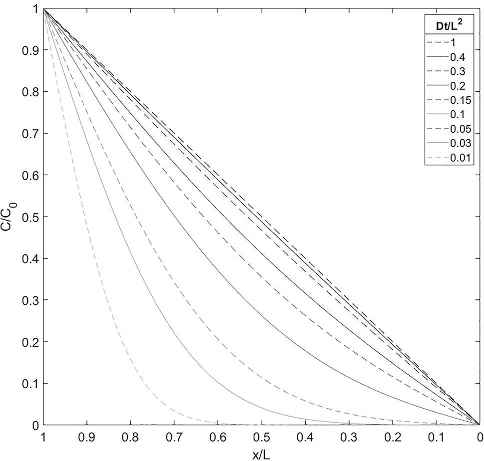
Diffusive normalised hydrogen concentration across a sheet of infinite width, with hydrogen entering at one surface (
A second example is a cylindrical tensile specimen with an initial uniform concentration
where
Figure 2 shows the normalised hydrogen concentration (
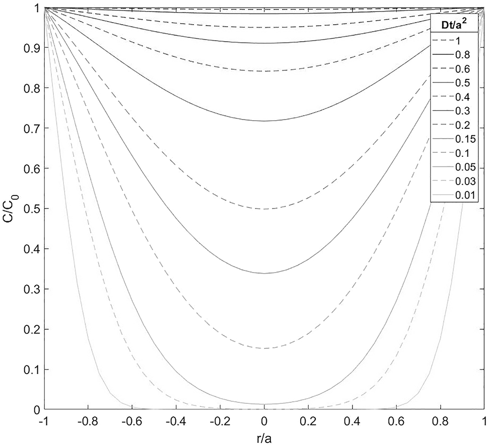
Diffusive normalised hydrogen concentration across a cross-section of a cylindrical specimen, which initially contains no hydrogen. The specimen is charged with a constant hydrogen fugacity resulting in a constant surface hydrogen concentration (
Hydrogen diffusivity varies with material, crystal structure, temperature, and stress (Lynch 2011a). Diffusivity increases with increasing temperature, as hydrogen atoms have greater kinetic energy and can more easily jump between interstitial sites. For a given material, the microstructure can also lead to variation in the diffusivity, especially in materials with complex microstructures. Ferritic steels, for example, have diffusivities that span 3 to 4 orders of magnitude at room temperature (Lynch 2011a). This is attributed to differences in hydrogen trap types and densities, which are discussed in greater detail in the following section on hydrogen trapping.
2.3 Hydrogen trapping
Hydrogen atoms are slightly larger than the interstitial sites between iron atoms that they occupy. This strains the lattice surrounding a hydrogen atom. Therefore, hydrogen tends to move to imperfections in the metal where the crystal lattice is slightly expanded (Birnbaum 2003; Louthan 2008). Such imperfections include (i) solute atoms, (ii) vacancies, (iii) boundaries such as grain boundaries and phase boundaries, (iv) dislocations, (v) interstitial sites in the first few atomic layers below free surfaces, (vi) interfaces between precipitates or inclusions and the matrix, (viii) crack tips, and (ix) voids. Hydrogen has a lower-potential energy at these sites, and as a result, these sites are known as traps (Carter and Cornish 2001; Lynch 2011a; Venezuela et al. 2016a). The binding energies of various traps in iron and steels have been tabulated by Ohaeri et al. (2021), Bhadeshia (2016), and Szost et al. (2013).
The average residence time of hydrogen at a trap increases with increasing binding energy. Increasing temperature increases the kinetic energy of the hydrogen atom, increasing the possibility of the hydrogen atom jumping out of the trap. Traps are referred to as irreversible if the binding energy exceeds a threshold binding energy. In irreversible traps, hydrogen atoms remain essentially completely trapped at room temperature.
The diffusivity of hydrogen at room temperature decreases with increasing number of traps and increasing trap strength (Lynch 2011a). Therefore, traps can reduce the degree of HEE by preventing hydrogen accumulation at potential crack initiation sites (Bhadeshia 2016). Some hydrogen traps, however, can also exacerbate HE by (i) accumulating hydrogen at regions of concentrated stress, (ii) by allowing hydrogen to recombine at large voids which causes pressure damage, or (iii) by acting as sources of internal hydrogen after diffusible hydrogen has egressed (Bhadeshia 2016; Lynch 2011a; Venezuela et al. 2016a). For these reasons, the interactions between hydrogen and trap sites often determine the mechanisms and manifestations of HE (Barnoush 2009; Barrera et al. 2018). The effective diffusivity (
2.4 Hydrogen solubility
The hydrogen concentration inside the steel in equilibrium depends on how much hydrogen is available at the surface. For steel exposed to pure gaseous hydrogen, the equilibrium hydrogen concentration in the steel depends on the external hydrogen partial pressure (Barthélémy 2006). If hydrogen trapping is ignored (for example, in pure annealed iron), the hydrogen concentration is related to hydrogen pressure by Sieverts’ law such that the hydrogen concentration,
where
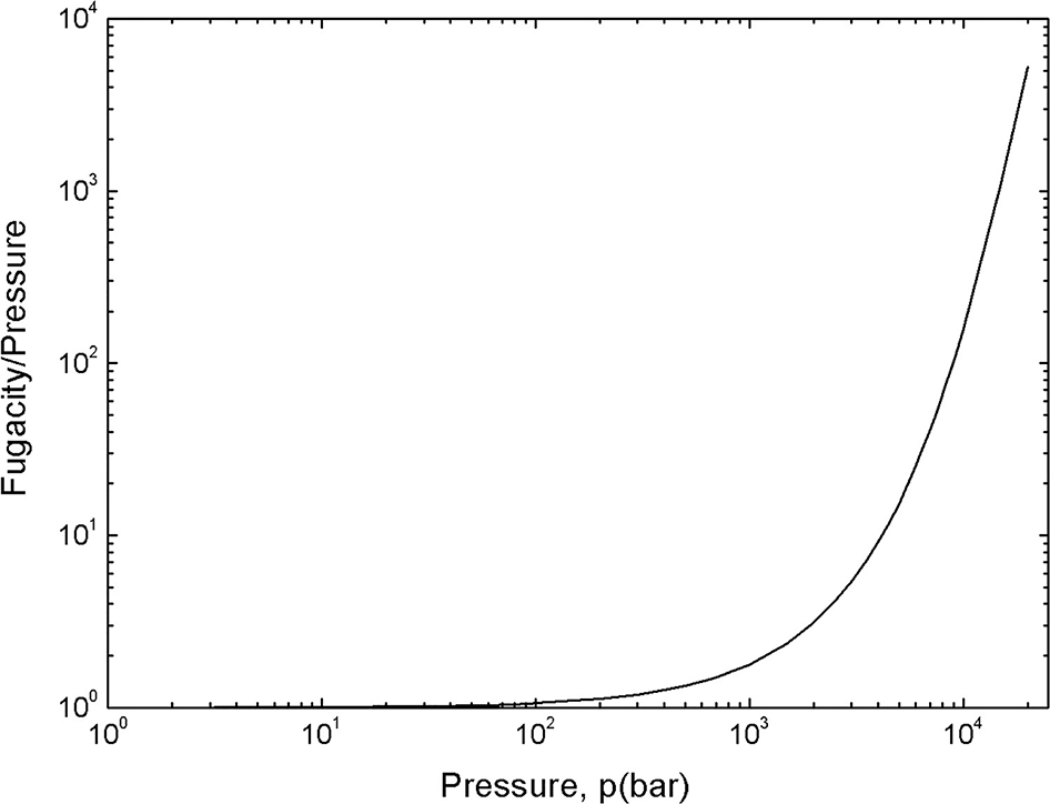
Fugacity/pressure plotted against hydrogen pressure. Reproduced from Venezuela et al. (2018) with permission.
For steels, hydrogen trapping needs to be incorporated into Sieverts’ law (Equation (8)) (Alraeesi and Gardner 2021; Lee 2016; Venezuela et al. 2018) by adding a trapped hydrogen concentration
This modified version of Sieverts’ law can be derived using statistical mechanics, as shown by Venezuela et al. (2018). Figure 4 shows the equilibrium hydrogen concentration for gaseous hydrogen charging of a medium-strength steel (3.5NiCrMoV), two advanced high-strength steels (980DP and MS1500) compared with literature data for pure annealed Fe (designated as Fe). The vertical intercepts in Figure 4 represent
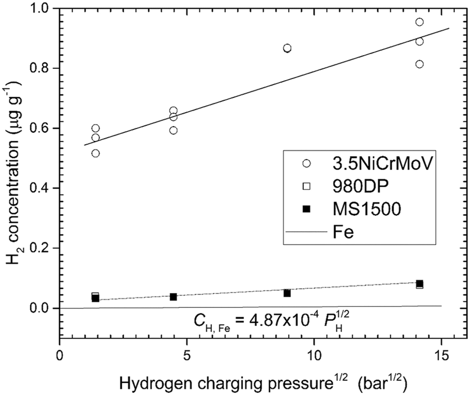
The equilibrium hydrogen concentration for gaseous hydrogen charging of a medium-strength steel (3.5NiCrMoV) (Venezuela et al. 2018), two advanced high-strength steels (980DP and MS1500) (Liu et al. 2018; Venezuela et al. 2017) compared with literature data for pure annealed Fe (designated as Fe) (Kiuchi and McLellan 1983). The equilibrium hydrogen concentration was measured using thermal desorption spectroscopy (TDS) and includes hydrogen in traps. Reproduced from Atrens et al. (2022) with permission.
3 HE in steels
3.1 Manifestations of HE
Typical manifestations of HE include a decrease in ductility, a decrease in fracture toughness, subcritical crack growth and altered fracture surfaces. Commonly, hydrogen causes a change from ductile to brittle fracture.
Subcritical crack growth is the propagation of a crack at an applied stress intensity factor below the critical stress intensity factor for the steel (the fracture toughness). Cracks can initiate at hydrogen traps at defects in the steel lattice or surface defects such as scratches (Lee 2016; Louthan 2008; Serebrinsky et al. 2004). The combination of a stress concentrator and hydrogen can lead to localised fracture, extending the crack tip. Hydrogen can then migrate to the new crack tip, and the process can repeat until the crack grows to a critical length whereupon brittle fracture occurs suddenly (Atrens et al. 2020; Louthan 2008; Serebrinsky et al. 2004). Subcritical cracking in the presence of hydrogen can be characterised using the threshold stress
Subcritical crack growth can lead to hydrogen-induced delayed fracture, which occurs when an applied stress (typically below the yield strength) leads to sudden fracture (Bhadeshia 2016; Jewett et al. 1973; Louthan 2008). The degree of HE increases with decreasing strain rate. Delayed fracture is the extreme case at a strain rate of 0, with a constant applied stress (Louthan 2008; Serebrinsky et al. 2004).
In low strength steels, HE appears not to result in subcritical crack growth (Atrens et al. 2020). Hydrogen can, however, decrease mechanical properties, particularly ductility, fracture properties and strength. HE is often characterised using the decrease in reduction-in-area (RA) and elongation (Jewett et al. 1973; Lee 2016; Oriani 1978). In low strength steels the yield strength can be reduced by up to 30% for moderate hydrogen contents (Atrens et al. 2020; Hirth 1980). Hydrogen generally does not affect the modulus of elasticity (Jewett et al. 1973; Lee 2016).
Hydrogen introduces new cracking mechanisms and decreases the fracture toughness of steels. Hydrogen decreases the strength of notched tensile steel specimens (Jewett et al. 1973; Lee 2016). Hydrogen reduces the stress intensity factor required for crack growth (i.e. subcritical crack growth) and larger amounts of hydrogen may also increase the subcritical crack velocity (Barnoush 2009; Louthan 2008). Hydrogen also increases susceptibility to fatigue and creep failure (Jewett et al. 1973; Lee 2016; Louthan 2008). The influence of hydrogen on fatigue depends on the frequency, as a lower frequency results in a lower strain rate which increases susceptibility to HE (Louthan 2008).
HE often changes the appearance of fracture surfaces. However, there is no single fracture mode common to all hydrogen embrittled materials as the fracture varies according to the steel and the environment (Louthan 2008; Oriani 1978). Intergranular fracture – fracture along grain boundaries – is common in hydrogen embrittled high-strength steels (Louthan 2008; Lynch 2011a; Serebrinsky et al. 2004). Intergranular fracture surfaces are bright and faceted, and can be covered in microscopic dimples. For some martensitic steels embrittled by hydrogen, the fracture is transgranular, as in the absence of hydrogen, but the dimples on the fracture surface are smaller and less deep (Lynch 2011a). Iron and low-carbon steels typically undergo ductile fracture without hydrogen, and undergo brittle quasi-cleavage in the presence of hydrogen. Quasi-cleavage is a kind of transgranular fracture, similar in appearance to cleavage but not along any known cleavage plane (Lynch 2011a; Xu and Rana 2008).
Other fractographical features in hydrogen embrittled steel include: (i) many surface cracks on the external surface perpendicular to and near the fracture; (ii) fish-eyes, especially in lower-strength steels, which are small, bright, circular regions of cleavage-like fracture that form during tensile failure, centred around hydrogen traps such as inclusions; and (iii) flakes or shatter cracks, which appear as small shiny regions on the fracture surface and form during solidification (Jewett et al. 1973; Louthan 2008; Lynch 2011a).
3.2 Steel attributes
In general, stronger steels are more susceptible to HE. High-strength martensitic steels are highly susceptible to HE, while lower-strength ferritic steels are less so (Lee 2016; Lynch 2011a). However, many attributes other than strength can influence HE susceptibility, such as microstructure, residual stresses, impurities, and hydrogen traps.
HE in martensitic steels (especially IHE) has been well studied due to (i) the embrittling influence of even small hydrogen concentrations and (ii) the potential for catastrophic delayed failure. In contrast, lower-strength ferritic steels require higher hydrogen concentrations for significant HE. Martensitic steels can undergo significant HE at hydrogen concentrations of ∼0.5 wt ppm, whereas ferritic steels may require hydrogen concentrations of ∼10 wt ppm (Lynch 2011a).
Low strength, stable austenitic steels have low susceptibility to HE (Barthélémy 2006; Lee 2016; Lynch 2011a; Michler et al. 2012). In addition, the austenitic FCC crystal structure has a much lower hydrogen diffusivity and higher hydrogen solubility than ferritic BCC and martensitic BCT structures (Lynch 2011a; Venezuela et al. 2016a). Many of the alloying elements that stabilise austenitic steel, such as nickel, carbon and manganese, have been reported to reduce HE (Barthélémy 2006).
Impurities such as sulphur, phosphorus and oxygen can exacerbate HE (Barthélémy 2006). These impurities can segregate at grain boundaries, weakening them, and large inclusions such as sulphides and oxides can trap enough hydrogen to act as crack initiation or void nucleation sites (Barthélémy 2006; Lynch 2011a). There is also some evidence that the presence of some impurities is necessary for hydrogen to alter the fracture mode by forming localised microvoids (Oriani 1978). The presence of strong hydrogen traps that do not serve as crack initiation sites can reduce HE susceptibility. This can be achieved by the presence of solute atoms, such as chromium, manganese, molybdenum, vanadium, and rare earth metals (Barthélémy 2006; Bhadeshia 2016). Titanium solute atoms trap hydrogen by forming carbides. Aluminium in martensitic steels also reduces HE (Bhadeshia 2016), which may be due to surface aluminium oxides hindering hydrogen entry.
Resistance to HE in steels can also be improved by subsequent processes that affect the microstructure. Heat treatments such as tempering, and normalising and quenching have been found to improve hydrogen resistance (Barthélémy 2006; Bhadeshia 2016). Cold working can create dislocations and internal cracks that may impede hydrogen diffusion (Bhadeshia 2016; Hirth 1980). In addition, component design features have a large influence on susceptibility. For example, stress concentrators can act as crack initiation sites in HEE (Barthélémy 2006).
3.3 Environmental factors
Environmental factors influencing HE include (Barthélémy 2006; Lynch 2011a; Venezuela et al. 2016a):
Hydrogen content
Stress, both applied and residual
Strain rate
Temperature
Surface condition of the steel
Presence of chemicals that facilitate or inhibit hydrogen uptake at the external surface.
3.3.1 Hydrogen concentration
The degree of hydrogen embrittlement increases with increasing hydrogen concentration. Figure 5 shows the notched tensile strength of a typical hot stamping steel against hydrogen concentration. The decrease in the notched tensile strength was accompanied by the change of fracture mode from microvoid coalescence for no hydrogen or for a low hydrogen concentration) to quasi-cleavage (at 2.6 wt ppm) to quasi-cleavage plus intergranular fracture for higher hydrogen concentrations (Lovicu et al. 2012).
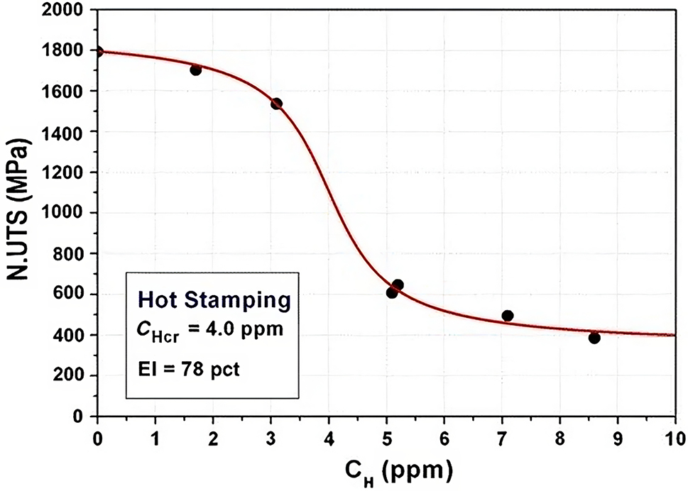
Notched tensile strength for a typical hot stamping steel decreased with increasing hydrogen concentration. Reproduced from Lovicu et al. (2012) with permission.
Even though HE generally increases with increasing hydrogen concentration, at high concentrations there exists a saturation point beyond which the effects of HE are relatively constant (Barthélémy 2006; Lynch 2011a). There also exists a similar minimum HE concentration, below which there are few HE effects (Bhadeshia 2016; Louthan 2008; Venezuela et al. 2016a).
3.3.2 Stress
The effects of HE, such as a brittle transition and subcritical cracking, usually require the steel to be stressed (Lee 2016). Without a sufficient applied or residual stress, the effects of hydrogen may be reversible after the hydrogen has egressed, provided that the hydrogen charging process did not cause damage such as blistering (Oriani 1978). Stress gradients, particularly at a crack tip, are also important because they cause hydrogen to accumulate at regions of high stress triaxiality (Barthélémy 2006; Serebrinsky et al. 2004).
3.3.3 Strain rate
The degree of HE increases with decreasing strain rate, in contrast to steel deformation in the absence of hydrogen, where strain rate usually has a relatively small effect on strength and fracture. The lowest strain rate of zero occurs hydrogen delayed fracture, where a constant applied stress below the yield strength can lead to fracture (Louthan 2008). There may be no observable influence of hydrogen above a critical strain rate, at which point the material fractures as it would in an inert environment (Lee 2016; Louthan 2008; Venezuela et al. 2016a).
An explanation for the greater influence of hydrogen at low strain rates is that hydrogen needs time to diffuse to successive regions of concentrated stress as cracking occurs (Lee 2016; Louthan 2008). In addition, HE may involve hydrogen trapped in dislocations, and at high strain-rates hydrogen cannot move as quickly as the dislocations.
3.3.4 Temperature
The influence of temperature on HE is associated with two important effects. First, hydrogen mobility increases with temperature, so that there is little hydrogen mobility at sufficiently low temperatures. Second, hydrogen is more likely to accumulate in traps at lower temperatures (Louthan 2008). In any case, there exists an intermediate temperature range over which HE may occur, as shown in Figure 6 for tensile tests carried out by Xing et al. (2021). The maximum HE in steels usually occurs near room temperature (Barthélémy 2006; Lee 2016; Louthan 2008). Above 100 °C HE is often negligible (Barthélémy 2006).
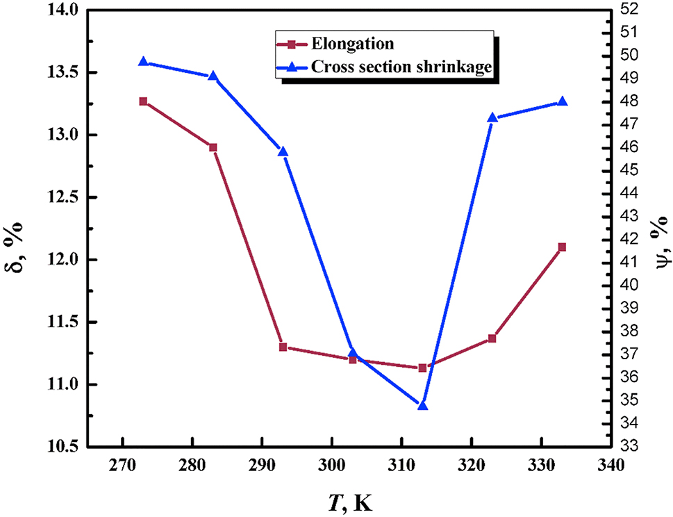
Influence of temperature on HE measured using tensile tests of X90 pipeline steel as measured by reductions in elongation (δ) and RA (Ψ). The hydrogen was charged electrochemically. Reproduced from Xing et al. (2021) with permission.
3.3.5 Surface conditions
A steel surface quickly forms an oxide film when exposed to air. These oxide films can significantly reduce hydrogen adsorption because (Bhadeshia 2016; Louthan 2008) diffusion through these films is greatly reduced. The diffusivities can be twelve orders of magnitude lower than in ferritic steel, so that even thin oxide films can slow hydrogen transport significantly (Bhadeshia 2016). Surface oxides are difficult to use to prevent HE, however, because (i) any scratches or corrosive pits on the surface can provide an entry point for hydrogen, (ii) applied tensile stresses tend to fracture brittle oxides, and (iii) hydrogen tends to reduce surface oxides as the oxides are typically not stable in the presence of hydrogen.
Surface treatments to impede HE can encounter the same issues. HE-reducing surface treatments that have been studied include (i) electroplated cadmium and nickel, which have low hydrogen diffusivities, (ii) black oxides, which reduce diffusion and surface crack nucleation, and (iii) coatings of hard ceramics such as aluminium oxide (Al2O3, aka. alumina), titanium carbide (TiC) and titanium nitride (TiN), which have low diffusivities (Barrera et al. 2018; Bhadeshia 2016).
3.3.6 Hydrogen absorption inhibitors
Certain impurities in hydrogen gas, such as oxygen and water vapour, act as inhibitors to the absorption of hydrogen (Barthélémy 2006; Jewett et al. 1973; Oriani 1978). Oxygen preferentially adsorbs onto the steel surface, decreasing the amount of adsorbed hydrogen. For example, Deimel et al. (1993) found that 19 vol ppm of oxygen was enough to significantly reduce ductility losses due to HE. This indicates that, for vessels with high hydrogen pressures, relatively low oxygen pressures could impede HE.
Other impurities that may also impede HE include carbon monoxide (CO), nitrous oxide (N2O) and sulphur dioxide (SO2) (Barthélémy 2006; Helmi 2016; Lee 2016). In liquid environments where hydrogen evolves electrochemically, other aqueous compounds can inhibit embrittlement, such as nitrites, organic nitrogen compounds, and phosphates (Lee 2016). In contrast, some gaseous impurities have been found to accelerate embrittling effects more than pure hydrogen, including hydrogen sulphide (H2S) and carbon dioxide (CO2) (Lee 2016).
3.4 Mechanisms of HE
Numerous mechanisms have been proposed for the HE of steels. The most popular include hydrogen enhanced local plasticity (HELP), hydrogen enhanced decohesion (HEDE), adsorption-induced dislocation emission (AIDE), hydrogen-enhanced strain-induced vacancy (HESIV), and the defactant concept.
It has also been proposed that in most cases, a combination of mechanisms occurs (Djukic et al. 2019; Lynch 2011a), and that the relative contributions of the various mechanisms vary according to material and environmental factors. HE mechanisms have been the subject of several recent in-depth reviews (Barrera et al. 2018; Birnbaum 2003; Djukic et al. 2019; Lynch 2011a; Robertson et al. 2015).
3.4.1 Hydrogen-enhanced decohesion
Hydrogen-enhanced decohesion (HEDE), also designated hydrogen-induced decohesion (HID) or simply decohesion, proposed that hydrogen lowers the bond strength between metal atoms (Barnoush 2009; Barrera et al. 2018; Lynch 2011a; Oriani 1978; Robertson et al. 2015). Hydrogen accumulated in the stress concentration region at a crack tip lowers the cohesive strength sufficiently to allow localised rupture, and thus crack propagation occurs at a lower stress intensity factor in the presence of hydrogen.
The HEDE theory was developed in 1959 by Troiano (2016) and subsequently by Oriani (1970). Evidence for HEDE has been developed for extremely high-strength steels (Barnoush 2009; Barrera et al. 2018; Birnbaum 2003; Lynch 2011a; Nagumo 2004). Difficulties in finding evidence for HEDE arise because (i) observing at the atomic scale at crack tips within the material is not yet possible and (ii) HEDE cannot be observed macroscopically as it requires high hydrogen concentrations that cannot be reproduced throughout the bulk material due to limited hydrogen solubility (Barrera et al. 2018; Lynch 2011a). Atomic simulations suggest that hydrogen does weaken interatomic bonds (Barrera et al. 2018; Birnbaum 2003; Lynch 2011a), and models based on HEDE have been used to effectively predict some experimental results (Barnoush 2009; Barrera et al. 2018).
Whether the localised stress levels and hydrogen concentrations required for HEDE occur in steels has been a source of controversy (Barnoush 2009; Birnbaum 2003; Lynch 2011a). Smooth intergranular fracture surfaces are sometimes used as evidence for the occurrence of HEDE as other proposed mechanisms should theoretically lead to dimpled fracture surfaces. It is sometimes concluded that HEDE is the dominant mechanism when the hydrogen concentration is high, and that intergranular fractures occur primarily by the HEDE mechanism (Barrera et al. 2018; Birnbaum 2003; Lynch 2011a).
3.4.2 Hydrogen-enhanced local plasticity
Hydrogen-enhanced local plasticity (HELP) proposes that hydrogen facilitates the localised movement of dislocations at a crack tip, causing the crack to propagate. HELP appears to be counterintuitive as increased dislocation motion might be expected to increase ductility. However, the HELP mechanism proposes that the increased plasticity is localised to the crack tip. This leads to crack propagation at stress intensity factors below the fracture toughness, manifesting as reduced macroscopic ductility (Barrera et al. 2018; Birnbaum 2003; Lynch 2011a; Oriani 1978).
Beachem (1972) was the first to suggest that HE occurred because hydrogen facilitated the movement of dislocations, proposing that hydrogen reduced the stress required for the initiation of dislocation movement. The HELP mechanism was based on the observation of ductile features on HE fracture surfaces, such as dimples which are indicative of ductile microvoid-coalescence (Barrera et al. 2018; Lynch 2011a; Robertson et al. 2015). The HELP mechanism was developed further by Birnbaum, Robertson and Sofronis, who provided experimental evidence of increased dislocation motion in the presence of hydrogen in thin iron films (Birnbaum 1989; Birnbaum 2003; Birnbaum et al. 2000). HELP is considered to be caused by trapped hydrogen in a dislocation core (i) reducing the activation stress required for dislocation motion, (ii) reducing resistance to dislocation motion through the lattice, and (iii) reducing interactions between dislocations and barriers to their motion, allowing dislocations to move through obstacles and group closer with other dislocations (Birnbaum 2003; Robertson et al. 2015). These interactions are caused by hydrogen modifying the stress fields of dislocations, reducing the strength of forces between dislocations and obstacles. This theory is known as ‘hydrogen shielding’ (Barrera et al. 2018; Birnbaum 2003; Lynch 2011a; Robertson et al. 2015). The HELP mechanism suggests that the influence of strain rate on HE is caused by the requirement that hydrogen moves along with dislocations, which travel too quickly at high strain rates (Lynch 2011a; Robertson et al. 2015).
Experiments in thin films have found that hydrogen increases the dislocation velocity, the rate of dislocation nucleation, and the density of dislocations when bunching together at an interface. The HELP mechanism is supported by theoretical simulations that show hydrogen lowers the stresses required for initiating dislocation motion (Lynch 2011a). In single crystals of iron tested at low strain rates, hydrogen has also been found to increase ductility, causing softening (Birnbaum 2003; Hirth 1980). Dimples on the fracture surface are often used as evidence for HELP causing microvoid coalescence.
Nonetheless, the HELP mechanism is controversial because hydrogen has elsewhere been found to obstruct the motion of dislocations, leading to strengthening. Proponents claim that these interactions between hydrogen and dislocations occur under different circumstances, and that the HELP mechanism is limited by the temperatures, stresses and strain rates during which hydrogen can follow a moving dislocation (Djukic et al. 2019; Robertson et al. 2015). In addition, much of the supporting evidence for enhanced dislocation motion was found in thin foils, which opponents to HELP claim is not applicable to HE in bulk metals (Barnoush 2009).
3.4.3 Adsorption-induced dislocation emission
Adsorption-induced dislocation emission (AIDE) proposes that HE occurs by the nucleation and propagation of dislocations at a crack tip. AIDE was developed by Lynch (1988, 2011a). AIDE proposes that hydrogen adsorption at the internal surface of a crack tip facilitates the nucleation of a dislocation by weakening interatomic bonds. This causes the crack to extend by an equivalent length. The dislocation motion away from the crack tip leads to the growth of microvoids ahead of the crack, further extending the crack. Lynch suggests that the mechanisms that depend on diffused hydrogen, such as HELP and HEDE, cannot explain the observations of HE at high crack velocities as diffusible hydrogen travels at much slower speeds. AIDE, in contrast, depends on adsorbed hydrogen, which can quickly adsorb from the crack interior onto the crack tip, and AIDE is therefore suggested to allow crack extension at high velocities (Lynch 2011a).
3.4.4 Hydrogen-enhanced strain-induced vacancy
Hydrogen-enhanced strain-induced vacancy (HESIV), sometimes called hydrogen-vacancy interactions, proposes that hydrogen enhances the creation of vacancies, and that the coalescence of these vacancies leads to crack growth. HESIV was proposed by Nagumo (2004) because of experimental observations of increased vacancy density in the presence of hydrogen. The HESIV mechanism suggests that, when strained, these vacancies coalesce into progressively larger voids in the high-strain region ahead of a crack. The phenomenon of delayed failure is then directly caused by the slow agglomeration of vacancies. HESIV is similar to HELP in that it results in ductile crack growth and is expected to produce dimples on the fracture surface (Nagumo 2004).
3.4.5 Defactant concept
The defactant concept proposes that hydrogen atoms lower the energy required to form defects such as vacancies, stacking faults and dislocations. Hydrogen stabilises vacancies, stacking faults and dislocations which is why these defects are hydrogen traps. The defactant concept attempts to provide a general explanation for multiple HE phenomena. This relatively recent proposal was developed by Kirchheim (2010) and Barnoush and Vehoff (2010).
4 Techniques to study HE
4.1 Tensile testing
Tensile testing is used to assess (i) how hydrogen influences strength and ductility and (ii) the HE mechanism from an evaluation of the fractography. Tensile testing to study HE is usually carried out at a slow strain rate because HE is exacerbated at slow strain rates. Tensile testing allows the evaluation of the influence of hydrogen on strength, ductility, and fracture mode. Tensile testing can also be used to detect subcritical crack growth by applying a constant stress below the yield stress for an extended period.
The ductility can be measured using the elongation (
where the subscript indicates tests in air or in the hydrogen environment. I closer to 100% indicates high HE, while I closer to 0% indicates low HE. Other hydrogen susceptibility indices can be calculated for reductions in other mechanical properties such as the ultimate tensile strength (UTS), and fracture toughness (Briottet et al. 2012; Venezuela et al. 2016b, 2020, 2021). The hydrogen susceptibility indices
The influence of strain rate on SCC and HE led to the development of the slow strain rate test (SSRT), standardised in ASTM G129 (ASTM International 2013). The SSRT is also designated the constant extension rate test (CERT). The extension of the specimen is typically increased linearly, so the (engineering) strain rate is kept constant in the initial linearly elastic region of the tensile test. The strain rate is usually between 10−5 s−1 and 10−7 s−1 (Henthorne 2016; Martínez-Pañeda et al. 2020). Throughout the test, the specimen is exposed to the embrittling environment. Various specimen designs have been used: (i) rectangular cross-section specimens; (ii) circular cross-section specimens; (iii) notched specimens to investigate the influence of stress-concentration; and (iv) hollow specimens to maintain a corrosive environment in a small volume inside the specimen.
An alternative to the SSRT is the linearly increasing stress test (LIST) in which the load is increased at a constant rate. The LIST and SSRT produce equivalent results in the initial elastic part of the tensile test up to the threshold stress (Atrens et al. 1993; Liu and Atrens 2013). The LIST has the advantage that it is concluded when the stress reaches the UTS, so it is typically much shorter than the SSRT. Like the SSRT, the LIST is used to expose specimens to a corrosive environment to study HE and SCC. Typically, LISTs are conducted along with the potential drop technique. The potential drop technique allows measurement of the threshold stress for the initiation of subcritical crack growth (or the initiation of stress corrosion cracking), or the yield stress if the HE begins at a stress greater than the yield stress (Ramamurthy and Atrens 1993; 2010; Ramamurthy and Atrens 2013; Ramamurthy et al. 2011).
4.2 Permeation testing
Permeation testing is used to determine the subsurface hydrogen concentration and the hydrogen diffusion coefficient, which determines the speed of hydrogen diffusion within the steel. Hydrogen permeation experiments typically use the Devanathan-Stachurski cell (Devanathan and Stachurski 1962, 1964). A schematic of the Devanathan-Stachurski cell is shown in Figure 7.
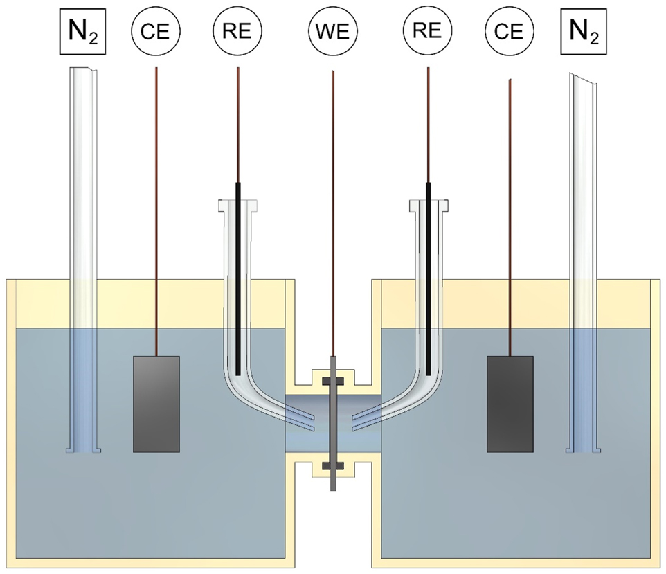
Design for the Devanathan-Stachurski cell used to measure hydrogen permeation electrochemically. The cell contains two three-electrode cells, each connected to a potentiostat. CE is the counter electrode, RE is the reference electrode, and WE is the working electrode. Nitrogen is bubbled through the solution to purge oxygen to low concentrations. Other inert gases can be used for this purpose, such as argon.
The Devanathan-Stachurski cell is made up of two three-electrode electrochemical cells, joined together by the thin steel specimen which is the working electrode for both cells. At the specimen surface in the cathodic cell (typically the left-hand cell), a constant potential is often applied which electrochemically produces a constant hydrogen fugacity so that hydrogen diffuses into the specimen. At the specimen surface in the anodic cell (typically the right-hand cell), a constant potential is applied, which oxidises the hydrogen atoms exiting the specimen. The diffusive hydrogen flux (
where
The analysis assumes that the subsurface concentration at the cathodic (entry) side is a constant (
The advantage of the Devanathan-Stachurski technique over other methods is that the accuracy depends on the accuracy of the measurement of the current, which can be more accurate than other measurement devices such as pressure transducers and mass flow meters used in gaseous permeation (Barrera et al. 2018; Devanathan and Stachurski 1962). This allows the measurement of small amounts of permeating hydrogen. The Devanathan-Stachurski cell can be inaccurate if hydrogen does not immediately exit the exit side of the specimen, causing the exit concentration to be greater than 0. Thus, the exit side is often electrochemically plated with a thin layer of palladium to facilitate hydrogen egress and oxidation (Oriani 1978). Other issues with the method can arise if the specimen surfaces are corroded due to the presence of a corrosive electrolyte.
Multiple methods have been used to evaluate the diffusivity from a permeation test (Haq et al. 2013). The breakthrough time (
The time lag method evaluates the diffusivity from the time (
A better approach is to use the whole permeation transient to evaluate the diffusivity. This method uses the Laplace transformation of Fick’s first law. The method evaluates the diffusivity which gives the best fit of the measured permeation transient to the theoretical permeation transients given by (Fallahmohammadi et al. 2013; Liu et al. 2014; Zakroczymski 2006):
where
Often in permeation experiments the area of the specimen available for hydrogen permeation is limited by the mounting of the specimen in the permeation cell. This permeation area is typically defined by O-rings that provide the seal that contains the electrolyte in each permeation cell. Such an arrangement means that the exposed area of the specimen is smaller than the total area of the specimen. Some hydrogen can diffuse into the outside regions of the specimen, a phenomenon known as an ‘edge effect’. Edge effects introduce some errors into the permeation evaluations. For a circular specimen, a thicker specimen (larger
Permeation experiments can also be conducted using a specimen exposed to gaseous hydrogen. These experiments are less common than electrochemical permeation experiments due to the difficulty in accurately measuring the small amounts of hydrogen exiting the specimen to determine the hydrogen flux. Gaseous hydrogen egress has been measured using a mass flow meter (Pizzi et al. 2008), a mass spectrometer (Frauenfelder 1968), an ion pump (Tsong-Pyng and Altstetter 1986), or a pressure transducer (Robertson and Thompson 1980). An example of a gas phase permeability cell that measures hydrogen flux using a pressure transducer is given in Figure 8.
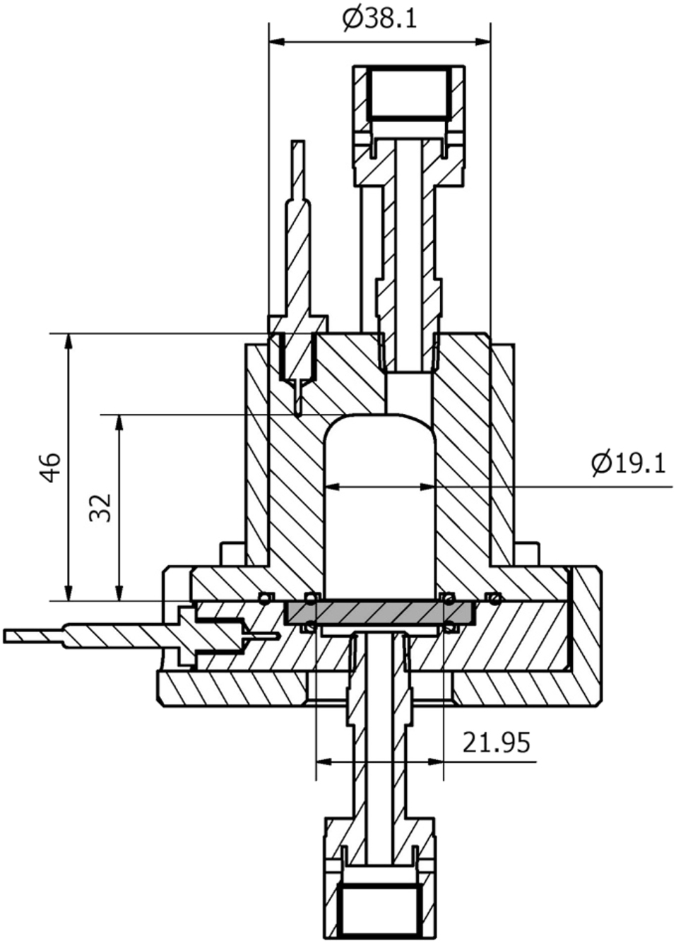
Diagram of a cell for gas phase hydrogen permeation. The steel specimen is identified by the grey colour. Hydrogen gas enters the cell at the top and diffuses to below the specimen. The pressure increase in the volume below the specimen is used to measure the amount of hydrogen diffusing through. Reproduced from Atrens et al. (2022) with permission.
The hydrogen permeation equations derived for electrochemical permeation experiments also apply to gas-phase permeation experiments, with the current densities replaced by fluxes in Equations (17) and (18), as indicated by:
Gas-phase permeation experiments give information that complements that from electrochemical permeation experiments. Gas-phase experiments allow the relationship between hydrogen partial pressure and subsurface hydrogen concentration to be evaluated. This allows the results of other HE studies that use electrochemical charging, such as tensile and fracture toughness studies, to be related to hydrogen pressure. Gas-phase experiments allow testing at elevated temperatures, whereas the temperature range is limited to below 100 °C in electrochemical experiments which use aqueous solutions. Gas-phase experiments also allow experimentation using gas mixtures containing hydrogen, such as mixtures of gases likely to be encountered in service, or the use of adsorption inhibitors such as oxygen.
If the same hydrogen concentration is introduced into a steel by both gas-phase and electrochemical charging, and the temperature is the same in both experiments, then the hydrogen fugacity during electrochemical charging and gas phase charging are the same (Liu et al. 2014; Venezuela et al. 2018). This allows evaluation of the hydrogen fugacity during electrochemical charging as indicated in Figure 9 (Liu et al. 2018; Venezuela et al. 2017).
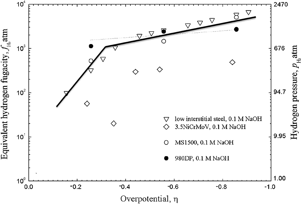
Relationship between hydrogen fugacity and overpotential during electrochemical hydrogen charging. The right-hand scale provides the equivalent hydrogen pressure. The fugacity of a gas corresponds to the pressure that the gas would have if the gas behaved as an ideal gas. Reproduced from Liu et al. (2018) with permission.
4.3 Fracture and fatigue
The impact of hydrogen on fatigue and fracture can be evaluated by comparing the results of experiments in air to those in hydrogen. Fatigue properties include the fatigue limit, the fatigue life, and the fatigue crack growth rate. Fracture mechanics experiments can measure crack velocity and the threshold stress intensity factor (
4.4 Measuring hydrogen content
The hydrogen content can be measured using permeation experiments, hot extraction methods, and using Thermal Desorption Spectroscopy (TDS). Hot extraction methods typically involve measuring the amount of hydrogen released from a specimen as the specimen is heated (sometimes quickly melted) using methods such as thermal conductivity or mass spectrometry. Thermal desorption spectroscopy (TDS) is used to measure the amount of hydrogen in a specimen while recording the temperatures at which hydrogen is released from the specimen, which typically produces a series of peaks at different temperatures. Each peak typically corresponds to a particular hydrogen trap, and TDS therefore allows the characterisation of the trap binding energies (Atrens et al. 2018; Tapia-Bastidas 2016). Other methods used to measure the amount of diffusible hydrogen include measurement of the volume of hydrogen released when the specimen is submerged in a liquid such as glycerol (Wang 2009), liquid paraffin (Dong et al. 2010) or silicone oil (Wang et al. 2015a).
4.5 Microanalysis
The location of hydrogen within steel is of interest in the study of HE. Direct imaging of hydrogen within iron and steel is difficult due to the low solubility of hydrogen and the weak interactions between hydrogen and electrons or X-rays. Imaging using neutron scattering, transmission electron microscopy (TEM), and helium bombardment can identify high concentrations of hydrogen, but not individual hydrogen atoms (Barrera et al. 2018). Individual deuterium atoms and their locations have been imaged using atom probes.
The hydrogen microprinting technique (HMT) is used to indirectly identify the location of hydrogen at a specimen surface. The exit surface of a (permeation) specimen is coated with a salt such as silver bromide (AgBr). Hydrogen exiting the specimen reduces the silver ions to silver crystals. The unreacted salt can then be washed away and the silver crystals can be visualised. HMT provides insight into the distribution of hydrogen and hydrogen trapping, however, it is limited to surface features and cannot be used to image hydrogen within the steel (Barrera et al. 2018; Ovejero-García 1985).
4.6 Stress corrosion cracking
Stress corrosion cracking (SCC) manifests as subcritical cracking under an applied stress in a corrosive solution. Well known SCC conditions include (i) steels in hydroxide solutions (caustic cracking), (ii) brass in ammonium solutions (season cracking), (iii) high pH ground water on the outside of gas-transmission pipelines, and (iv) high-strength steels in water, particularly sea water. SCC likely encompasses many mechanisms including the metal dissolving at the crack tip (frequently called anodic dissolution), or adsorbed ions at the crack tip weakening metallic bonds (Lee 2016; Lynch 2011b; Ramamurthy and Atrens 2013). HE is one of the proposed mechanisms of SCC and is considered the likely SCC mechanism for high-strength steels in water. SCC can be studied using some of the same experimental techniques as HE, such as slow tensile tests.
5 HE in pipeline steels
5.1 Pipeline steel grades
The most common steel grades used in (Australian) natural gas transmission pipelines are those standardised in the American Petroleum Institute (API) 5L standard, ‘Specification for Line Pipe’ (American Petroleum Institute 2018; Ohaeri et al. 2021). These include the low-strength grades A25, A, and B, as well as the X series which ranges from X42 to X120. The numbers in the X series steels designate the minimum yield strength in the non-SI unit of kilo-pounds per square inch (ksi).
API 5L grades are low-carbon steels (in part to ensure good weldability). The maximum carbon content varies across the different grades from 0.21 to 0.28 wt %. The API 5L standard also specifies maximum percentages for alloying elements, as well as a maximum ‘carbon equivalent’ that estimates the contributions of alloying elements to the hardness of the steel and to the weldability of the steel. The heat treatments described in the API 5L standard are tempering, normalising (or annealing), stress relieving, quenching and tempering, and age hardening (American Petroleum Institute 2018). The microstructure of pipeline steels is mostly ferrite and pearlite, with some steels containing bainite and martensite (Ohaeri et al. 2021; Xu 2012). Higher strength pipeline steels (X70 and above) are more recent grades, developed using processing techniques including continuous casting, controlled thermo-mechanical rolling, micro-alloying, and quenching (Ohaeri et al. 2021), although these processes are also used for the production of the lower strength steel grades.
Pipelines may be extruded as pipe or fabricated from rolled metal plate joined longitudinally using a seam weld. Seam welds may be produced with a filler metal, as is the case for submerged-arc welding (SAW) and gas metal-arc welding (GMAW), or without a filler metal, as is the case for continuous welding, electric welding and laser welding. Pipes with seam welds may have one longitudinal weld, two longitudinal welds, or a helical seam weld. Welds which join two pieces of pipe circumferentially are known as girth or jointer welds (American Petroleum Institute 2018).
During welding, the microstructure of the steel on either side of the weld may be altered. This area is known as the heat-affected zone (HAZ). The weld may have higher hardness than the base metal, with hardness through the HAZ decreasing with distance from the weld (Olabi and Hashmi 1996). The weld metal frequently contains bainite and different morphologies of ferrite, including acicular ferrite, which resembles needle-shapes and has high toughness (Boumerzoug et al. 2010; Chaveriat et al. 1987; Olabi and Hashmi 1996). The welding method influences the microstructure of the weld and HAZ.
The longest natural gas pipeline in Australia is the 1539 km Dampier Bunbury Natural Gas Pipeline (DBNGP) in WA. Much of the main pipe length is X65 steel (Dampier Bunbury Pipeline (DBP) 2011). Other major Australian pipelines include (i) the Amadeus Gas Pipeline in NT, constructed mostly from X60 steel (APT Pipelines 2015), (ii) the Goldsfields Gas Pipeline in WA, constructed mostly from X70 steel (Goldfields Gas Transmission Joint Venture 1994), and (iii) the South East Australia Gas (SEAGas) pipeline in SA, constructed mostly from X70 steel (Langley et al. 2010). Over time, the construction of gas pipelines in Australia has tended from lower strength to higher strength pipeline steels (Langley et al. 2010), although this trend may change as hydrogen transmission becomes a consideration.
In order to establish the safe limits of hydrogen blending into existing natural gas pipelines, the resistance of these pipeline steels to HE must be evaluated, including the relationship between susceptibility and steel grade, microstructure, and the susceptibilities of the weld and HAZ.
5.2 Summary of HE research
A literature review using the Web of Science found 256 articles relevant to HE in pipeline steels. The number of articles is shown in Figure 10, with articles grouped by topic. The largest share of research articles has focused on the effects of hydrogen on mechanical properties of the pipeline steels. These mechanical properties included tensile properties, fracture and fatigue. ‘Hydrogen charging’ studies typically involved hydrogen induced cracking (HIC) or permeation experiments. Articles listed as ‘SCC’ focused on stress-corrosion cracking but involved hydrogen charging, typically using simulated soil solutions. Articles listed as ‘Other’ studied topics that were tangential to HE such as sulphate-reducing microorganisms and methods of taking field measurements of hydrogen content in pipeline walls. Table 1 lists the specific types of experiments that have been conducted on pipeline steels charged with hydrogen.
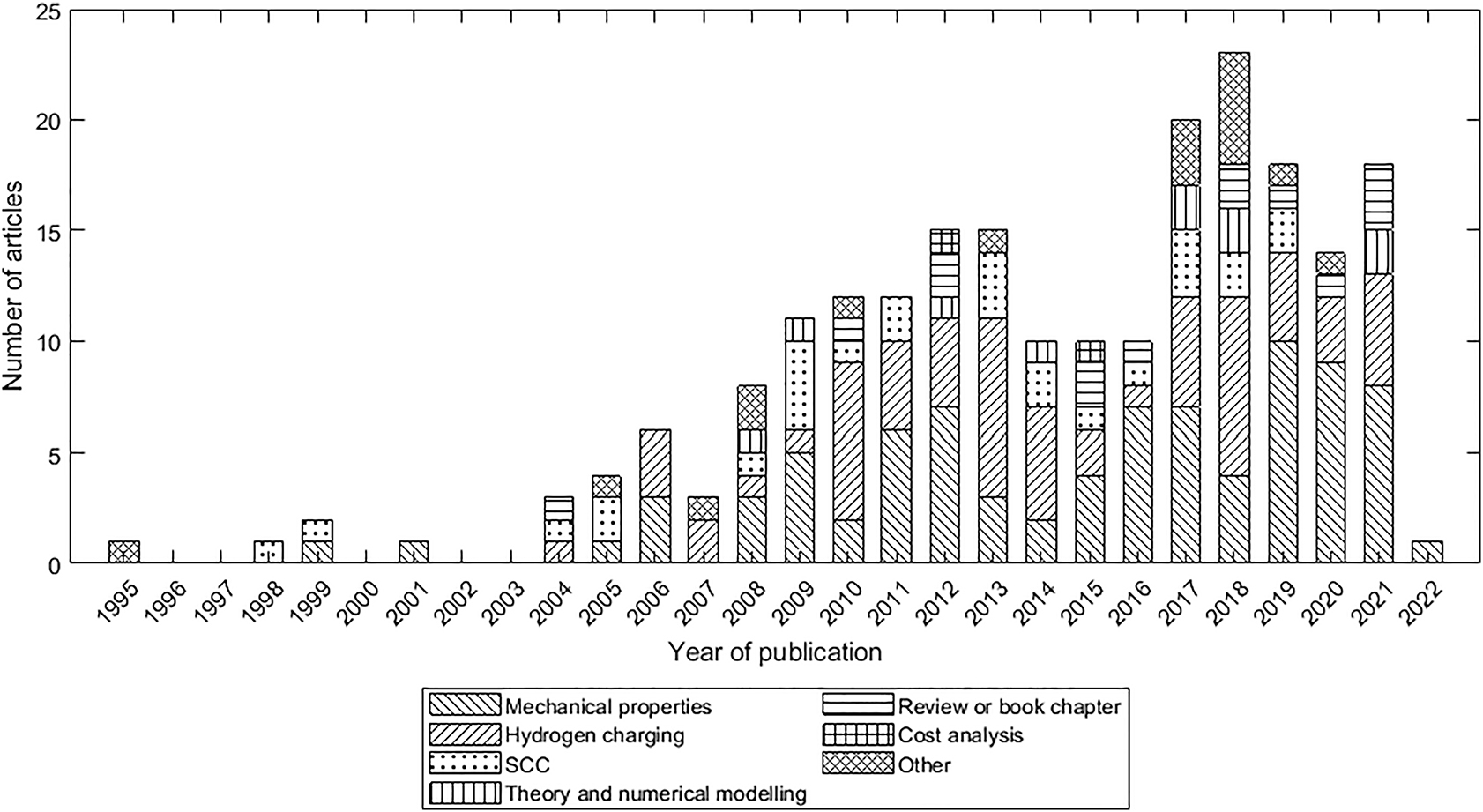
Results of a Web of Science search for hydrogen in pipeline steels, showing the number of journal articles published each year from 1995 to 2022. Articles are group according to their focus. SCC articles expose steel to a corrosive environment where hydrogen is an electrochemical by-product and not the primary focus.
HE-experiment types conducted in studies of pipeline steels.
| Type | Experiment | Standards | Number of studies |
|---|---|---|---|
| Tensile | Slow strain rate tensile (SSRT) | ASTM G142, ASTM G129 | 30 |
| Small punch (SP) | ASTM E3205 | 2 | |
| Tensile test | ASTM G142, ASTM E8 | 28 | |
| Permeation | Devanathan-Stachurski method | ASTM G148 | 34 |
| Fatigue | Beam specimen | 2 | |
| Compact tension (CT) | ASTM E647 | 19 | |
| Edge notched tension | 2 | ||
| Eccentrically loaded single-edge notched tension (ESET) | 3 | ||
| Spiral notch torsion test (SNTT) | 1 | ||
| Wedge open loading (WOL) | ISO 7539 | 1 | |
| Fracture toughness | Modified wedge open loading (MWOL) | 1 | |
| Circumferentially notched tension (CRT) | ASTM G142 | 9 | |
| Compact tension (CT) | ASTM E647 | 2 | |
| Hollow circumferentially notched tension | 1 | ||
| Three point bending (TPB)/Single-edge notched bending (SENB) | ASTM E1820 | 7 | |
| Single-edge notch tension (SENT) | 5 | ||
| Impact | Charpy pendulum impact test | ASTM E23 | 7 |
| Distribution | Hydrogen microprint technique | 2 | |
| SCC | Hydrogen-induced cracking | NACE TM0284 | 24 |
| U-bend test | ASTM G30 | 1 | |
| Electrochemical corrosion | Electrochemical impedance spectroscopy (EIS) | ASTM G106 | 11 |
| Potentiodynamic polarisation | ASTM G61 | 18 | |
| Scanning vibrating electron technique (SVET) | 2 | ||
| Hydrogen content | Thermal desorption spectroscopy (TDS) | 6 | |
| Displacement methods | 10 | ||
| Hydrogen analyser | 2 | ||
| Hot extraction method | 2 | ||
| Potentiometer discharging | 4 | ||
| Other | Disc pressure test | 2 |
-
The standards column gives the designations of testing standards for the experiment. Studies grouped under the generic ‘Tensile test’ had a moderate strain rate and did not qualify as SSRT experiments.
Figure 11 shows the steel grade investigated in journal articles identified in the literature review. The most frequently researched steels were X70 and X80. Both of these steels have been used for natural gas pipelines (Langley et al. 2010), and are more susceptible to HE than lower strength pipeline steels. Fewer articles have been published on lower strength pipeline steels such as X42 and X46. This is presumably because these steels are resistant to HE and therefore research into their hydrogen susceptibility would produce negative results. Some studies investigated steel grades from standards other than API 5L, such as F22 from the ASTM A182 standard (Fassina et al. 2011), A333Gr6 from the ASTM A333 standard (Zheng et al. 2012), and P110 from the API 5CT standard (Majchrowicz et al. 2019). Some researchers investigated steels that did not conform to a standard, listed in Figure 11 under ‘Novel steels’. These included steels with high copper contents (Shi et al. 2016), and steel microalloyed with niobium and titanium (Torres-Islas et al. 2013).
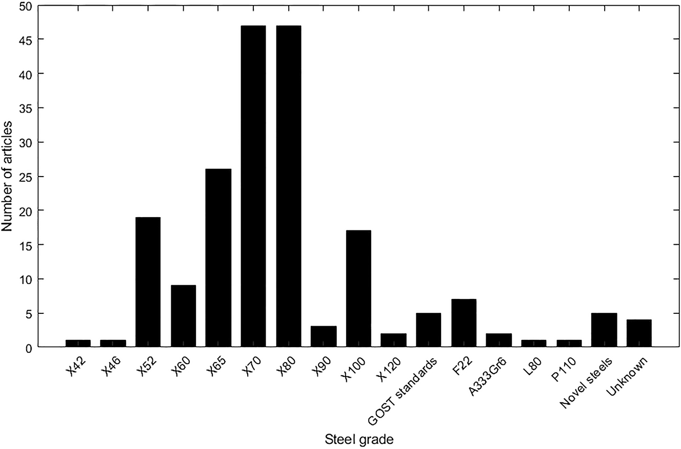
Number of articles relating to different grades of pipeline steel. Novel steels are new steels created for the research that are not graded. Unknown steels were referred to by the authors as pipeline steels but the grade was not defined.
There have been previous reviews of HE in pipeline steels. Eliassen (2004) and Cabrini et al. (2015) focused on hydrogen generated by cathodic protection in submarine pipelines. Findley et al. (2015) reviewed the mechanisms behind the initiation of HIC, concluding that reversibly-trapped hydrogen was chiefly responsible for crack initiation. Ghosh et al. (2018) also reviewed HIC susceptibility and the influence of microstructure and chemical composition on HIC. Ohaeri et al. (2018) covered the many kinds of hydrogen degradation in pipeline steels and their relationships with microstructure. Xu (2012) reviewed the HE susceptibility of low-carbon steels generally, including low-strength pipeline steels. These steels generally had low HE susceptibility, although some mechanical properties were reduced – particularly fracture toughness and elongation to failure. For lower-strength carbon steels, studies reported similar HE susceptibility for the base metal, HAZ and weld. In higher-strength pipeline steels, there was some evidence that the weld and HAZ were most susceptible to HE. No subcritical crack growth was recorded in the base metal of X42 and X70 steels at hydrogen pressures up to 310 bar (Cialone and Holbrook 1985), although there was some evidence of subcritical crack growth in the weld and HAZ. Chemical composition influenced HE: carbon content increased HE susceptibility, as did manganese, chromium, molybdenum and vanadium. There was some evidence that microalloying niobium and titanium decreased HE. In reviewing the HE mechanisms, Xu concluded that HELP was the dominant mechanism in low-carbon steels, due in part to the high diffusivities of these steels which allow hydrogen to follow moving dislocations.
Ohaeri et al. (2021) reviewed hydrogen permeation and the influence of hydrogen on strength and fatigue properties of pipeline steels. Nanninga et al. (2010) reviewed the effect of hydrogen on fatigue crack growth in pipeline steels. They concluded that the crack growth rates in these steels were significantly affected by hydrogen, even in low-strength steels such as X42, and there was no strong relationship between pipeline steel strength and HE fatigue susceptibility. Although fatigue properties are an important consideration in the design of gas transmission pipelines carrying hydrogen, the literature on fatigue has been covered in detail by the previously mentioned reviews. Therefore, fatigue properties are not included in this review. This review will instead give an overview of previous research into tensile properties, hydrogen permeation, and fracture properties.
5.3 Pipeline degradation
A consideration in the repurposing of natural gas pipelines for hydrogen transmission is the possibility of degradation of pipelines during time in service. The mechanical properties of pipeline steels after field operation have been compared to samples of the same steel that have been kept in reserve. This has allowed the effects of service exposure to be isolated. Service exposure has been reported to reduce the impact toughness, fracture toughness, and ductility (Gabetta et al. 2008; Nykyforchyn et al. 2018, 2022b). The results for yield and tensile strength vary, as operation has been found to decrease or increase both yield and tensile strength (Gabetta et al. 2008; Nykyforchyn 2021; Nykyforchyn et al. 2022b; Zvirko et al. 2022). Nykyforchyn et al. (2022b) found service exposure caused the electric potential of the steel fracture surface to become more negative, from which they suggested that electrochemical testing of pipelines in the field could be used to estimate the degree of degradation.
In addition, the HE susceptibility of pipeline steels might increase over the steel lifetime. Figure 12 shows the results of Nykyforchyn et al. (2022a) who found that the effect of hydrogen on strength (YS and UTS) and ductility (elongation and reduction of area) of a VST3ps pipeline steel after 52 years of operation was greater than a reserve sample of the same pipeline steel. Zvirko et al. (2022) conducted tensile tests of 17H1S pipeline steel and found that the steel after 36 years of operation had a hydrogen embrittlement index of 38% compared with 6% for reserve steel.
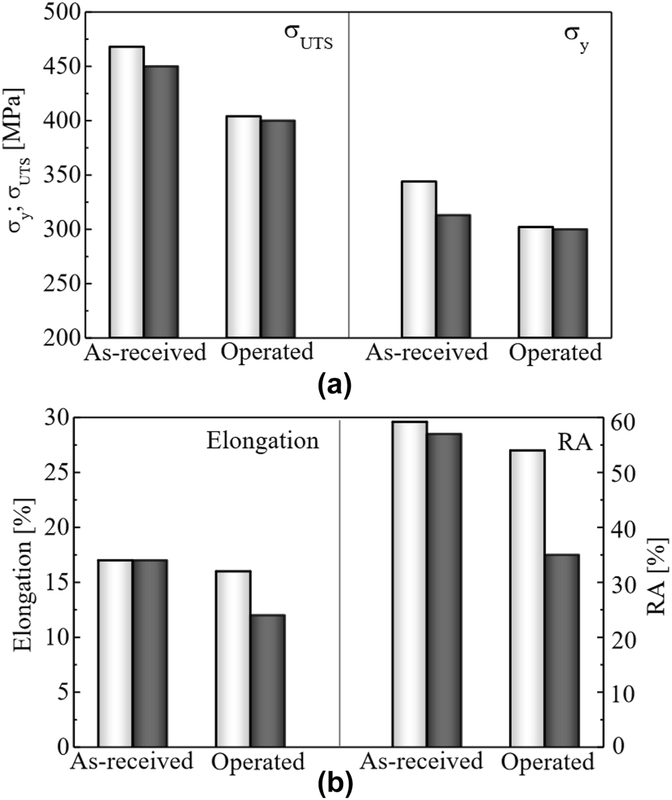
Results for strength (a) and ductility (b) in VST3ps steel as-received and after 52 years of service exposure (designated operated). White bars are without hydrogen, and black bars are after hydrogen charging for 100 h in an aqueous H2SO4 solution (pH 3.5) at a current density of 1 mA/cm2. Reproduced from Nykyforchyn et al. (2022a) with permission.
Multiple mechanisms were proposed for the observed pipeline degradation. These include (i) natural aging, (ii) stress corrosion cracking, (iii) HIC during service in the field, and (iv) the production of internal defects, such as voids, in the steel over time due to stress (Nykyforchyn 2021; Nykyforchyn et al. 2010, 2018). Nykyforchyn et al. proposed the void model due to the observed increase in HE susceptibility, which they suggested was due to the creation of hydrogen traps. Gabetta et al. (2008) found field operation resulted in reduced hydrogen diffusivity, which would support this theory as traps reduce hydrogen diffusion.
5.4 Tensile properties
The previous sections of this review indicated that low-carbon ferritic steels, including low-strength pipeline steels, were resistant to HE. The literature review also indicated that higher-strength steels tend to be more susceptible to HE. It was therefore expected that studies into the tensile properties of pipeline steels in hydrogen would find that pipeline steels have low values of the hydrogen embrittlement index (I), which would increase with increasing pipeline steel strength.
Table 2 summarises the results of studies that conducted tensile tests of pipeline steels in hydrogen, listed in order of publication date. These include studies that used gaseous hydrogen and studies that generated hydrogen electrolytically. The I values (the hydrogen embrittlement index as calculated from either elongation or RA) and changes in strength (YS and UTS) that resulted from the charging conditions are included. In the electrolytic studies, the most frequently used electrolyte was sulfuric acid (H2SO4), used in almost all studies. Most experimenters also used a recombination poison, such as arsenic trioxide (As2O3), potassium arsenate (KH2AsO4), thiourea (SC(NH2)2), and ammonium thiocyanate (NH4SCN). Charging current densities ranged from 0.1 mA/cm2 to 66 mA/cm2. In gaseous hydrogen studies, pressures ranged from 1 to 690 bar. Following Table 2 is an elaboration of these studies, and thereafter there is a synthesis of trends revealed by these studies.
Summary of tensile studies investigating HE in pipeline steels.
| References | Steel grade | Specimen type | Strain rate (s−1) | IHE/HEE | Hydrogen delivery | Charging conditions | Hydrogen embrittlement index (I) | Change in YS/UTS |
|---|---|---|---|---|---|---|---|---|
| Lunarska et al. (1997) | 13CrMo44 | Rectangular, 3 × 2 mm gauge dim. | Not disclosed | IHE | Electrolytic: 0.1 N H2SO4 | Not disclosed | 0.10 ppm: −3% 0.21 ppm: 0% 0.47 ppm: 11% 1.40 ppm: 17% |
Not measured |
| Gu et al. (1999) | X52, X80 | Cylindrical, unspecified dimensions | 2.2 × 10⁻⁶ | IHE | Electrolytic: 1 M H2SO4 and 250 ppm As2O3 | 3 mA/cm2 for 24 h | X52: None X80: 9% |
None |
| Torres-Islas et al. (2005) | X70 | Cylindrical, longitudinal, 2.5 mm gauge diameter | 1.36 × 10⁻⁶ | IHE | Electrolytic: 0.5 M H2SO4 and 100 ppm As2O3 | 0.1 mA/cm2 for 1 h | As received: 10% Quenched: 85–90% |
Not measured |
| Hardie et al. (2006) | X60, X80, X100 | Cylindrical, longitudinal, 3.21 mm gauge dia. | 2.8 × 10⁻⁵ | IHE | Electrolytic: 0.5 M H2SO4 and 5 g/L KH2AsO4 | 3–66 mA/cm2 for 15 min | At 66 mA/cm2, X60: 64% X80: 78% X100: 86% |
No clear change |
| Dong et al. (2009b) | X100 | Rectangular, unspecified orientation, 0.5 mm gauge thickness | 1.25 × 10⁻³ | IHE | Electrolytic: 0.5 M H2SO4 and 0.25 g/L As2O3 | 20 mA/cm2 for 1–8 h | 1 h precharging: 48% 5 h precharging: 61% 8 h precharging: 76% |
Slightly reduced |
| Moro et al. (2010) | X80 | Cylindrical, longitudinal, 6 mm gauge dia. | 5 × 10⁻⁵ | HEE | Gaseous: pure H2 | 1–300 bar | 1 bar: 0% 50 bar: 41% 100 bar: 67% 300 bar: 68% |
Reduced 1–3% |
| Stalheim et al. (2010) | X60, X70, X80 | Cylindrical, not from pipe, unspecified diameter | 10−5 – 10−4 | HEE | Gaseous: pure H2 | 55–207 bar | At 55 bar, X60: 49% X70: 45% X80: 38% |
None |
| Alhussein et al. (2011) | X52 | Rectangular, transverse, 8 × 4 mm gauge dim. | Not disclosed | HEE | Electrolytic: NS4 solution | −1 V (SCE) | 42% | Reduced 7–9% |
| Arafin and Szpunar (2011) | X80, X100 | Cylindrical, transverse, 2.54 mm gauge dia. | 9.3 × 10⁻⁷ | HEE | Electrolytic: 1 N Na2CO3 and 1 N NaHCO3 | Potentials from OCP to −1.2 V (SCE) | X80 at OCP, 45%; at −1.0 V, 51%; at −1.2 V, 61% X100 at OCP, 29%; at −1.0 V, 51%; at −1.2 V, 75% |
Not measured |
| Lee et al. (2011) | X65 | Cylindrical, hollow, 6 mm gauge dia. | 7 × 10⁻⁶ – 7 × 10⁻⁴ | HEE | Gaseous: pure H2 | 200 bar | 20% | Reduced 3–5% |
| Nanninga et al. (2012) | X52, X65, X100 | Unspecified, both longitudinal and transverse | 7 × 10⁻³ | HEE | Gaseous: pure H2 | Between 2 and 690 bar | At 138 bar H2, X52: 22% X65: 28% X100: 50% |
Possibly increased strength in X100 |
| Neeraj et al. (2012) | X65, X80 | Not disclosed | 1 × 10⁻⁵ | IHE | Electrolytic: 0.5 M H2SO4 and 0.005 g/L As2O3 | 5 mA/cm2 for 4 h | X65: 20% X80: 20% |
Not measured |
| Torres-Islas et al. (2013) | Novel steel | Cylindrical, both longitudinal and transverse, 2.5 mm gauge dia. | 1.36 × 10⁻⁶ | IHE | Electrolytic: 0.5 M H2SO4 | 0.1 mA/cm2 for 30 min | Longitudinal: 27% Transverse: −10% (A negative I indicates increased ductility in hydrogen) |
Not measured |
| Xiong et al. (2015) | X80 | Cylindrical, not from pipe, 2.5 mm gauge dia. | 1 × 10⁻⁵ | HEE | Gaseous: H2 and CO2 | H2 1 bar, CO2 2–10 bar | At H2 1 bar, CO2 10 bar: 3% At H2 1 bar, CO2 5 bar: 6% At H2 1 bar, CO2 2 bar: 22% |
Reduced YS and UTS |
| Hejazi et al. (2016) | X70 | Cylindrical, hollow, transverse, 6 mm gauge dia. | 3.75 × 10⁻⁵ | HEE | Gaseous: pure H2 | 100 bar | 22–25% | YS unchanged, UTS reduced by 4% |
| Meng et al. (2017) | X80 | Cylindrical, both smooth and notched, longitudinal, 6 mm gauge dia. | 1.1 × 10⁻⁵ | HEE | Gaseous: H2 and N2 | Total 120 bar: H2 partial pressure 6, 12, 24, 60 bar | At H2 60 bar, From ε: 19% From RA: 17% |
None |
| Zhang et al. (2017b) | X80 | Cylindrical, transverse, 5 mm gauge dia. | 1 × 10⁻⁶ | HEE | Electrolytic: 0.5 M H2SO4 with 0.2 g/L SC(NH2)2 | 1 mA/cm2 (CH ≈ 1 ppm) | 63% | Strength reduced by ∼20% |
| Cabrini et al. (2019) | X70SS, X80, X100 | Cylindrical, unspecified orientation, 3 mm gauge dia. | 1 × 10⁻⁶ | HEE | Electrolytic: 3.5 vol% NaCl | OCP, −1 V, −2 V (SCE) | At −2 V, X70SS: 37% X80: 48% X100: 42% |
Not measured |
| Han et al. (2019) | X100 | Rectangular, transverse, 10 × 2 mm gauge dim. | 2 × 10⁻⁴ | IHE | Electrolytic: 0.5 M H2SO4 with 0.5 g/L SC(NH2)2 | 25 mA/cm2 for 3, 6, and 12 h | 12 h precharging: 46.3% | YS and UTS reduced slightly |
| Rahman et al. (2019a) | X60, X60SS, X70 | Rectangular, transverse, 6–12 mm gauge depth × 12.5 mm width | 4.17 × 10⁻⁵ | IHE | Electrolytic: 0.2 M H2SO4 with 0.5 g/L NH4SCN | 20 mA/cm2 for 1–24 h | Maximum I: X60: 58% X60SS: 72% X70: 42% |
Increased YS and UTS |
| Rahman et al. (2019b) | X70 | Rectangular, both longitudinal and transverse, 12.5 × 12 mm gauge dim. | Not disclosed | IHE | Electrolytic: 0.2 M H2SO4 with 3 g/L NH4SCN | 20 mA/cm2 for 1, 8, 15 h | 1 h: 33% 8 h: 46% 15 h: 50% |
Strengthened after 1 h, no change at longer charging times |
| Singh et al. (2019) | X65 | Rectangular, not from pipe, 5 × 4 mm gauge dim. | 5 × 10⁻⁵ | IHE | Electrolytic: 1 N H2SO4 with 1.4 g/L NH4SCN | 20 mA/cm2 for 4 h (CH ≈ 5.4 ppm) | From ε: 16% From RA: 39% |
Increased YS, unaffected UTS |
| Zhou et al. (2019) | X80 | Rectangular, unspecified orientation, 5 × 2 mm gauge dim. | 2 × 10⁻⁴ – 2 × 10⁻⁵ | HEE & IHE | Electrolytic: 0.5 M H2SO4 with 2 g/L SC(NH2)2 | 2.5–5.0 mA/cm2, IHE was 12 h | 2.5 mA/cm2: 71% 5.0 mA/cm2: 79% Full results in Table 3 |
None |
| Bai et al. (2020a) | X42 | Rectangular, longitudinal, 5 × 3 mm gauge dim. | 5.4 × 10⁻⁵ | HEE | Electrolytic: 0.5 M H2SO4 with 0.5 g/L Na4P2O7 | 0.05–10 mA/cm2 | 0.05 mA/cm2: 34% 1 mA/cm2: 42% 2.5 mA/cm2: 59% |
YS and UTS increased by 1–3% |
| Li et al. (2020a) | X80 | Rectangular, longitudinal, 10 × 1.5 mm gauge dim. | 5.13 × 10⁻⁴ | IHE | Electrolytic: 0.5 M H2SO4 and 0.25 g/L As2O3 | 10 mA/cm2 for 1 h | Average 22% | Slightly strengthened |
| Li et al. (2020b) | X80 | Rectangular, longitudinal, 10 × 1.5 mm gauge dim. | 5.13 × 10⁻⁴ | IHE | Electrolytic: 0.5 M H2SO4 and 0.25 g/L As2O3 | 10 mA/cm2 for 1 h | Average 19% | UTS and YS increased by 5–15% |
| Nguyen et al. (2020a) | X70 | Cylindrical, transverse, 6 mm gauge dia. | 2.62 × 10⁻⁵ | HEE | Gaseous: H2 and CH4 mixture; and pure H2 | 1:99 bar H2/CH4; 100 bar H2 | 1 bar: 3% 100 bar: 33% |
∼1% strength reduction |
| Nguyen et al. (2020c) | X70 weld | Cylindrical, transverse, 6 mm gauge dia. | 2.62 × 10⁻⁵ | HEE | Gaseous: H2 and CH4 | 1 bar H2, 99 bar CH4 | From ε: 18% From RA: 25% |
∼1% strength reduction |
| Ohaeri et al. (2020) | X70 | Rectangular, longitudinal, 4 × 3.125 mm gauge dim. | 1 × 10⁻³ | IHE | Electrolytic: 0.2 M H2SO4 and 3 g/L NH4SCN | 20 mA/cm2 for 12 h | Thermomechanically processed specimen: 50% | UTS increased by 4–8% |
| Boot et al. (2021) | X60 base metal and weld | Cylindrical, hollow, both smooth and notched, longitudinal, 8 mm gauge dia. | 1 × 10⁻⁵ | HEE | Gaseous: pure H2 | 30–100 bar | Base 100 bar: 28% Weld 100 bar: 11% Weld 70 bar: 11% Weld 30 bar: 11% |
None |
| Nguyen et al. (2021) | X70 base metal and weld | Cylindrical, transverse, 6 mm gauge dia. | 2.62 × 10⁻⁵ | HEE | Gaseous: H2 and CH4 mixture; and pure H2 | 1:99 bar H2/CH4; 100 bar H2 | Base 1 bar: 0.9% Base 100 bar: 51% Weld 1 bar: 25% |
∼1% strength reduction |
| Xing et al. (2021) | X90 | Rectangular, transverse, 6 × 2 mm gauge dim. | 1 × 10⁻⁶ | HEE | Electrolytic: NS4 simulated soil | No applied current | 0 °C: 6% 40 °C: 21% 60 °C: 15% |
Possible increased strength |
| Nykyforchyn et al. (2022a) | VST3ps | Rectangular, transverse, 4 × 1.2 mm gauge dim. | 3 × 10⁻⁴ | IHE | Electrolytic: H2SO4, unspecified molarity | 1 mA/cm2 for 100 h | 0–2% | Strength reduced by 4–8% |
-
The specimen type column includes the specimen orientation, designated either longitudinal or transverse. Longitudinal means the specimen axis is aligned with the pipe axis, or the rolling direction of the steel. Transverse means the specimen axis is along the curvature in the pipe wall. Transverse specimens represent the typical axis of pipeline fracture due to hoop stresses in the pipe wall. The hydrogen embrittlement index is calculated based on ductility. IHE designates studies precharged with hydrogen, while HEE designates studies with hydrogen charging during the tensile test. The hydrogen embrittlement index was evaluated from the change in ductility.
Tensile experiments have also been used to investigate SCC of pipeline steels. SCC may involve the electrochemical generation of hydrogen alongside other corrosive processes (Ramamurthy and Atrens 2013). Numerous studies have conducted tensile tests with cathodic hydrogen charging in a corrosive solution (Li et al. 2006; Liang et al. 2009; Liu et al. 2012, 2016; Sant’Anna et al. 2016; Song et al. 2020a, b; Torres-Islas and Gonzalez-Rodriguez 2009; Wan et al. 2017; Zhu et al. 2016). Other studies have investigated the effects of hydrogen sulphide (H2S) gas on pipeline steel tensile properties which also involves simultaneous corrosion and HE (Anijdan et al. 2021; Bai et al. 2020b; Silva et al. 2021; Titov et al. 2019; Wang et al. 2015a, b). Though these findings are important for pipeline safety, they are not pertinent to hydrogen pipelines and hydrogen blending into natural gas pipelines and therefore are not included in Table 2.
Gu et al. (1999) investigated IHE as part of a study of the SCC in X52 and X80 pipeline steels. The IHE study involved conducting SSRTs for specimens in air and precharged with hydrogen. The parameters of this precharging are given in Table 2; the resulting hydrogen concentration was not measured. For X80 steel, the hydrogen precharging did not affect the YS or UTS but reduced the strain at fracture by 9%. Both uncharged and hydrogen precharged specimens had similar fracture surfaces that were indicative of ductile fracture. The results for SSRTs of X52 steel were not given, presumably because there was no evidence of HE in this lower-strength steel.
Torres-Islas et al. (2005) investigated the effect of heat treatments on IHE in X70 using SSRT. The specimens were precharged electrolytically and tested in air. The heat treatments investigated were spray quenching, water quenching, and quench and tempering. The as-received steel had a mostly ferritic microstructure, while the water sprayed steel had a mostly bainitic microstructure with some acicular ferrite section. These specimens underwent ductile fracture and had low susceptibility to HE with I values of 10% and 5%, respectively. The water quenched steel and quench and tempered steel had martensitic microstructures, and underwent brittle fracture after hydrogen charging with respective I values of 85% and 90%. In another study, Torres-Islas et al. (2013) investigated HE in a novel microalloyed steel similar to the API 5L class pipeline steels. This study compared tensile specimens from the longitudinal and transverse directions with respect to the pipe axis. Transverse specimens are likely more representative of real pipeline failure as this relates to the probable orientation of fracture in a pipe wall due to hoop stresses. The transverse specimens were somewhat less susceptible to HE than the longitudinal specimens, although this trend was inconsistent.
Hardie et al. (2006) studied the effect of IHE on X60, X80 and X100 pipeline steel using tensile tests precharged with current densities varying from 11 to 70 mA/cm2, with a charging time of 15 min. The hydrogen concentrations resulting from these current densities were not measured. The results were highly variable, possibly due to the low charging time. The changes in RA after hydrogen charging were similar for the three steel grades, dropping from an average of around 80% in the uncharged specimen to around 30% in the specimen charged at 10 mA/cm2. Reductions in elongation after charging in the X80 and X100 were greater than in X60. As the current density increased further, RA and elongation remained mostly constant – this is likely due to the hydrogen concentration reaching the saturation level (Barthélémy 2006; Lynch 2011a). At high current densities (>60 mA/cm2) ductility may have decreased further in the X80 and X100 steels, although this finding may be unreliable due to the variation in results, and the authors had no explanation for this observation. Their fractographic analysis indicated both intergranular and transgranular cracking in the charged specimens, although the fracture was primarily transgranular. Hydrogen induced cracking had occurred on the specimen surface, and the cracks were oriented in the rolling direction of the pipe.
The authors argued that the absorbed hydrogen inside the specimen was the primary cause for losses in ductility. Their evidence was that a specimen charged at 66 mA/cm2 resulted in severe surface cracking, but after the same specimen was allowed to outgas hydrogen for a week, the RA and elongation were similar to the uncharged specimen.
In the same paper, Hardie et al. (2006) reported no HE for X60 and X80 specimens precharged in gaseous hydrogen at 325 bar, and then tensile tested in gaseous hydrogen at 1.7 bar. Given the severe embrittlement that occurred after electrochemical charging, this suggests that the hydrogen concentrations achieved in the electrochemical charging conditions were much larger than in these gaseous conditions and were not relevant to gas pipeline conditions where the maximum gas pressure is 200 bar.
Several studies have focused on the relationship between electrolytic precharging time and IHE. Dong et al. (2009b) carried out IHE tensile tests of X100 after charging specimens for 1 h–8 h. The reduction in area decreased from approximately 33% in the uncharged specimen to 17%, 13%, and 8% after 1, 5, and 8 h of precharging, respectively. The decrease in ductility is attributed to increasing hydrogen concentrations resulting from increasing charging time. A similar decrease in ductility was reported in a later study by Dong et al. (2010) using X80 steel.
Rahman et al. (2019a) found that electrochemical hydrogen precharging X60, X60 stainless (X60SS), and X70 steels between 1 and 24 h increased both the UTS and YS by approximately 10%. Ductility reduced up to a maximum at 15 h, when the I was 58%, 71%, and 45% in the three steels. HE declined at longer charging times, which was attributed to a lower hydrogen concentration in the specimens due to the particular electrolytic hydrogen charging conditions.
Han et al. (2019) found that electrochemical hydrogen charging X100 pipeline steel reduced both YS and UTS, in contrast to the hydrogen-strengthening results from Rahman et al. (2019a) in which strength was increased by hydrogen in the lower-strength pipeline steels. I increased with charging time, up to 46% at 12 h, the maximum charging time tested. Increasing pre-strain hardened the steels, leading to increased YS and UTS and decreased elongation and RA. Pre-strain also increased the effects of HE, leading to reduced ductility.
Moro et al. (2010) found that the YS and UTS of X80 was unchanged in gaseous hydrogen up to 300 bar, but the ductility was decreased, with I of around 68% between 100 and 300 bar. At 50 bar I was 41%. At 1 bar there was only a minor hydrogen effect on the elongation, and no effect on reduction in area. The fracture surfaces of the embrittled specimens displayed less necking and quasi-cleavage fracture. As in the work of Hardie et al. (2006), the brittle fracture surface contained cracks oriented in the rolling direction. The authors attributed this to separation at the interfaces between pearlite and ferrite in the X80 steel. The specimens also showed external cracks close to the fracture surface running circumferentially around the surface.
Lee et al. (2011) found a negligible effect on the YS and UTS for X65 exposed to 200 bar hydrogen gas inside hollow tensile specimens. Hydrogen reduced the strain to fracture from 12% to 9%. Reducing the strain rate reduced the strain to fracture slightly further. Fractography showed a mixture of quasi-cleavage brittle fracture propagating from the inside of the specimen exposed to hydrogen and transitioning to a ductile fracture near the outer specimen surface. The amount of brittle fracture increased with lower strain rates.
Nanninga et al. (2012) found that X52, X65 and X100 in gaseous hydrogen at pressures ranging from 2 to 690 bar had negligible changes in YS and UTS. HE ductility losses increased with increasing steel strength. For X52, X65, and X100 at 138 bar hydrogen, I (as calculated from elongation) was 22%, 28%, and 50%, respectively. These results showed that even low-strength pipeline steels such as X52 can undergo HE at a hydrogen partial pressure of 138 bar. Transverse specimens were only slightly more susceptible to HE, even though they were generally stronger and more brittle than longitudinal specimens. X100 in hydrogen possibly underwent a small increase in YS and UTS, although the increases were within experimental error. 2 bar hydrogen reduced the reduction in area of X100 from 76% to 68% but had no effect on the elongation. Higher hydrogen pressures reduced reduction in area further: 55 bar hydrogen reduced RA to 30%; 276 bar hydrogen reduced RA to 23%. At 690 bar hydrogen saturation likely occurred. The authors found that there was no strong relationship between decreasing strain rates and HEE.
During fracture beyond the UTS, there was surface cracking in the necking region of the longitudinal specimens, extending in rings perpendicular to the strain direction. In the transverse specimens, the surface cracks were instead at an angle to the specimen axis, such that the cracks travelled in a helix along the specimen surface. This anisotropic surface cracking indicates that cracking occurred along interfaces in the steel microstructure that depended on the rolling direction – possibly (as noted by the authors) ferrite-pearlite interfaces. SEM imaging of the embrittled fracture surfaces showed a central ductile fracture region and a brittle region around the edges of the cylindrical specimen (the region expected to have the highest hydrogen concentration). The authors reported that the hydrogen fracture mode was quasi-cleavage (Nanninga et al. 2012).
Xiong et al. (2015) investigated X80 steel in a gaseous mixture of H2 maintained at 1 bar and CO2 from 2 bar to 10 bar. At 10 bar CO2 there was no HE. At 5 bar CO2 there was reduced YS (from approximately 660 MPa–600 MPa), UTS (approximately 710 MPa–650 MPa), and strain to fracture (11%–10%). At 2 bar CO2 partial pressure, strain to fracture decreased further (9%), although the effect on the strength was negligible. These results indicate that HE can be significantly reduced by limiting the access of hydrogen to the steel surface by mixing with another gas with a higher partial pressure. Microanalysis of the fracture surface of the baseline nitrogen specimen showed necking and some deep MVC dimples characteristic of ductile pipeline steels. The embrittled specimens had less necking and a ductile central region and a brittle outer region. The central ductile region also had shallower dimples than those in nitrogen and some quasi-cleavage surfaces.
Hejazi et al. (2016) found for hollow X70 tensile specimens charged with 100 bar gaseous hydrogen at room temperature that I (calculated from elongation) was 25%. YS was unaffected and the UTS was reduced by ∼4%. Increasing the temperature to 50 °C reduced I to 18%, and at 100 °C I was 14%, which was attributed to steel softening at the increased temperatures.
Meng et al. (2017) found for X80 in gas mixtures of nitrogen and hydrogen, with the total pressure maintained at 120 bar and hydrogen partial pressures of 6, 12, 24 and 60 bar, that (i) YS and UTS were unaffected by hydrogen, (ii) I increased with increasing hydrogen partial pressure, up to 16% at 24 bar hydrogen, and (iii) beyond 24 bar, the degree of HE remained essentially constant, with an I value of 17% at 60 bar hydrogen. This indicates that saturation of HE occurred at around 24 bar hydrogen. Furthermore, this X80 steel had some resistance to HE because the losses of ductility were small even when saturated with hydrogen.
The results of Zhou et al. (2019) are shown in Table 3. They found that X80 precharged at 5 mA/cm2 (Test 2) resulted in a 35% I, while hydrogen charging during the test using the same conditions (Test 3) resulted in a 79% I, and hydrogen precharging plus charging during the test (Test 4) increased I further to 88%. Increasing the strain rate from 2 × 10⁻⁵/s to 2 × 10⁻⁴/s reduced I (i) from 35% (Test 2) to 10% (Test 5), and (ii) from 99% (Test 4) to 80% (Test 6). Hydrogen had almost no effect on the YS across all tests. Annealing the X80 increased the YS and reduced the susceptibility to HE (Tests 7–9). Microanalysis of the fracture surfaces showed a reduced MVC dimple size in the IHE specimen (Test 2). The HEE (Test 4) fracture surface had few dimples and was quasi-cleavage fracture, and the fracture crack had extended inwards from the specimen surface.
Yield strength and hydrogen embrittlement index (I) measured using SSRTs of an X80 steel under various charging conditions.
| Test no. | Heat treat condition | Precharge time | Tensile environment | Current density (mA/cm2) | Strain rate (s−1) | Yield strength (MPa) | I (%) |
|---|---|---|---|---|---|---|---|
| 1 | As received | None | Air | No | 2 × 10⁻⁵ | 560 | – |
| 2 | As received | 12 h | Air | 5 | 2 × 10⁻⁵ | 560 | 35 |
| 3 | As received | None | Hydrogen | 5 | 2 × 10⁻⁵ | 560 | 79 |
| 4 | As received | 12 h | Hydrogen | 5 | 2 × 10⁻⁵ | 560 | 88 |
| 5 | As received | 12 h | Air | 5 | 2 × 10⁻⁴ | 560 | 10 |
| 6 | As received | 12 h | Hydrogen | 5 | 2 × 10⁻⁴ | 560 | 80 |
| 7 | Annealed | None | Air | No | 2 × 10⁻⁴ | 602 | – |
| 8 | Annealed | 12 h | Air | 5 | 2 × 10⁻⁴ | 598 | 1 |
| 9 | Annealed | 12 h | Hydrogen | 5 | 2 × 10⁻⁵ | 601 | 86 |
| 10 | As received | None | Hydrogen | 2.5 | 2 × 10⁻⁵ | 560 | 71 |
-
I was calculated relative to elongation in air (Tests 1 and 7). Reproduced from Zhou et al. (2019) with permission.
Xing et al. (2021) found reduced ductility for X90 charged with hydrogen in NS4, a solution used to simulate hydrogen charging due to corrosion in soil, at temperatures from 0–60 °C. The degree of HE was a maximum at 40 °C, in agreement with the common observation of a maximum HE at around room temperature in steels (Lee 2016; Louthan 2008). The maximum decrease in elongation was small, from around 14% in air to 11% under HE. YS slightly increased, although there was no relationship between temperature and YS. At 30 °C, the fracture surface contained quasi-cleavage features. At 40 °C, the temperature with the greatest embrittlement, the fracture surface was evenly brittle with no dimples. From 50 °C onwards, dimples reappeared and necking resumed (Xing et al. 2021).
Figure 13 presents the dependence on hydrogen content of the hydrogen embrittlement index (I), evaluated from the reduction in elongation at failure from studies where this data is available. The higher-strength X80 (Zhang et al. 2017b; Zhou et al. 2019) had higher I values than the lower-strength steels such as X42 and X65 (Bai et al. 2020a; Neeraj et al. 2012; Singh et al. 2019), despite the X65 having higher hydrogen concentrations. This indicates that X65 is significantly less susceptible to HE than X80 for hydrogen concentrations up to 5.5 wt ppm. Lunarska et al. (1997) found that 13CrMo44 pipeline steel had no decrease in ductility with up to 0.2 wt ppm hydrogen, and I was 11% at 0.5 wt ppm, and 17% at 1.5 wt ppm. These results support the existence of a minimum hydrogen concentration below which HE does not occur. Zhang et al. (2017b) found an internal hydrogen concentration of 1 ppm was enough to cause significant embrittlement in X80 steel. Increasing the current density beyond that which produced 1 wt ppm resulted in significant damage to the specimen, including blistering even with no applied stress.
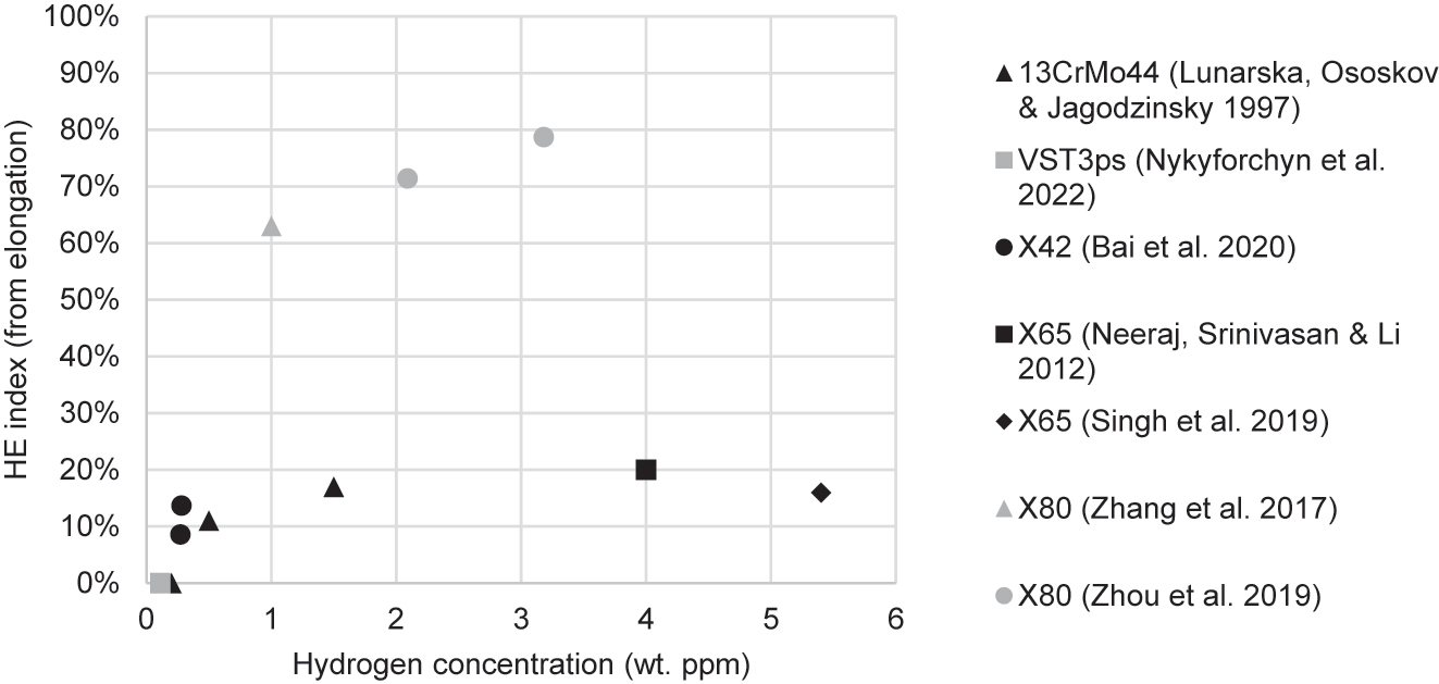
Hydrogen embrittlement index (I) against subsurface hydrogen concentration.
The lower strength steels (13CrMo44, X42, and X65) had similar I values across a wide range of hydrogen concentrations (from 0.27 to 5.4 wt ppm). This suggests that hydrogen saturation occurred under increasing internal hydrogen concentration.
Figure 14 shows that the pipeline steels (X70, X80, X100) exposed to 1–2 bar hydrogen typically indicated a small degree of HE (Moro et al. 2010; Nanninga et al. 2012; Nguyen et al. 2020a). Not included in Figure 14 is the data of Xiong et al. (2015) who found that X80 charged at 1 bar hydrogen had an I value of 22%, but this was in the presence of 2 bar CO2 which may have had a confounding effect. At 100 bar hydrogen and above, there was significant embrittlement (I> 50%) in X70 (Nguyen et al. 2020a), X80 (Moro et al. 2010), and X100 (Nanninga et al. 2012), but less embrittlement for X52, X60 and X65 exposed to 100–150 bar hydrogen which had lower I values between 20 and 30% (Boot et al. 2021; Lee et al. 2011; Nanninga et al. 2012). This indicated a general relationship between increasing steel strength and increasing HE susceptibility. However, an exception to this trend was the I of 25% for X70 in 100 bar hydrogen (Hejazi et al. 2016). This variation indicates that HE resistance can vary significantly among steels of the same grade with similar strengths and chemical compositions.
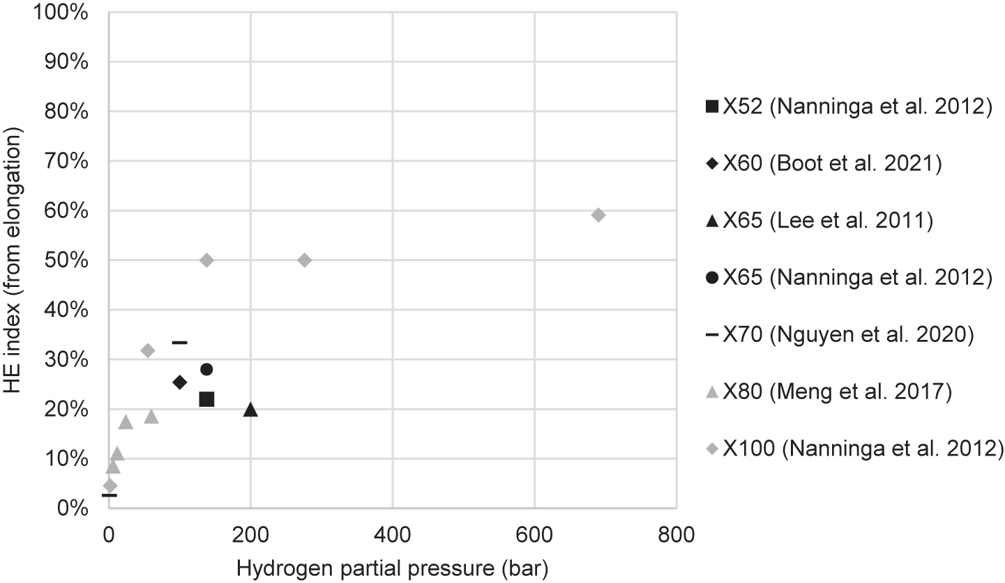
HE index (I) against hydrogen partial pressure in tensile studies that used gaseous hydrogen.
Hydrogen saturation is indicated by the hydrogen pressures beyond which HE did not continue to increase (or continued to increase slowly). Figure 15 shows estimates of hydrogen saturation conditions. The maximum pressure shown was the pressure which exhibited the largest embrittling effect. Greater pressures caused a similar degree of embrittlement. The minimum pressure shown is the next lowest pressure tested below the saturation pressure. This gives a range over which hydrogen saturation may have occurred. All gaseous tensile studies that tested multiple pressures of pure hydrogen found evidence of hydrogen saturation, indicating that this is a general phenomenon. Included in Figure 15 is the work of Xu and Rana (2008), who conducted tensile tests in low-carbon steels similar to pipeline steels, ASME SA-106 and ASME SA-372, and found that saturation was reached at or below 69 bar.
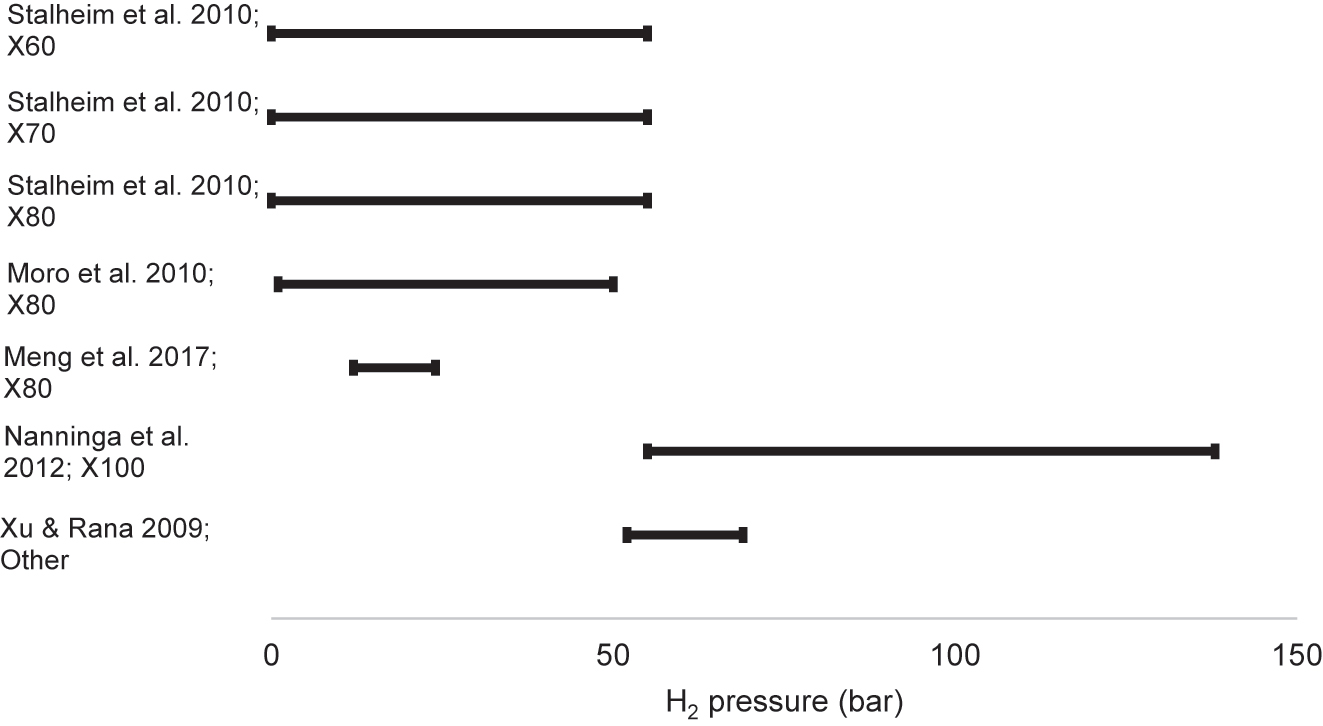
Hydrogen pressure ranges at which hydrogen saturation may have occurred in tensile studies. Higher hydrogen pressures tested beyond the maximum pressures shown caused no additional embrittling effect.
Most of the studies indicated that hydrogen saturation occurred at below 55 bar. The results of Nanninga et al. (2012), however, indicated that saturation occurred at a pressure between 55 bar and 138 bar. These results may indicate that X100 was sufficiently different from lower-strength pipeline steels to cause a noticeable difference in its HE susceptibility.
Not shown in Figure 15 are the results of electrochemical tensile studies. Bai et al. (2020a) found saturation occurred at 2.5 mA/cm2 for an X42 steel. Hardie et al. (2006) found HE reached a maximum at a current density of 10 mA/cm2 for X60, X80 and X100 steels, although ductility may have decreased further at much higher current densities (>60 mA/cm2). Stalheim et al. (2010) found similar results for X60, X70 and X80. These results indicate that hydrogen saturation may be largely independent of strength and microstructure, and the variation in results across different studies may be due to differences in charging or testing conditions. Similarly to Hardie et al. (2006), Nanninga et al. (2012) found evidence of further embrittlement occurring at very high concentrations beyond saturation, in their case at high pressures above 500 bar.
Figure 16 shows the HE index calculated from the UTS, charted against hydrogen partial pressure. The percentage changes were small across all pressures and steel grades. Some studies found hydrogen increased strength slightly, and some found hydrogen reduced strength slightly, but there was no relationship between increased or reduced strength and other variables such as steel strength or hydrogen partial pressure. Previous reviews of HE have noted that hydrogen generally does not affect the strength of high-strength martensitic steels but can reduce the strength of low-strength ferritic steels (Atrens et al. 2020; Hirth 1980), but there was no clear relationship between steel strength and strength change in hydrogen in the literature reviewed.
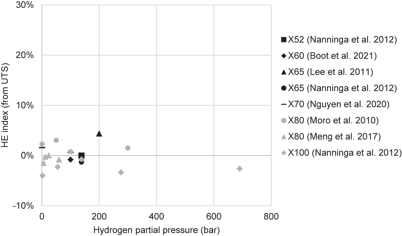
Percentage reduction of the UTS after charging in hydrogen compared to the UTS in air, charted against hydrogen partial pressure. A negative HE index value indicates that UTS was increased after hydrogen charging.
Figure 17 shows that UTS was generally reduced by a larger amount in the electrochemical studies than in the gaseous studies shown in Figure 16. Unlike the gaseous charging studies, there is evidence that hydrogen affects the UTS in the electrochemical charging studies for substantial hydrogen concentrations above ∼0.5 wt ppm. However, there is no clear relationship between increasing internal hydrogen concentration and UTS.
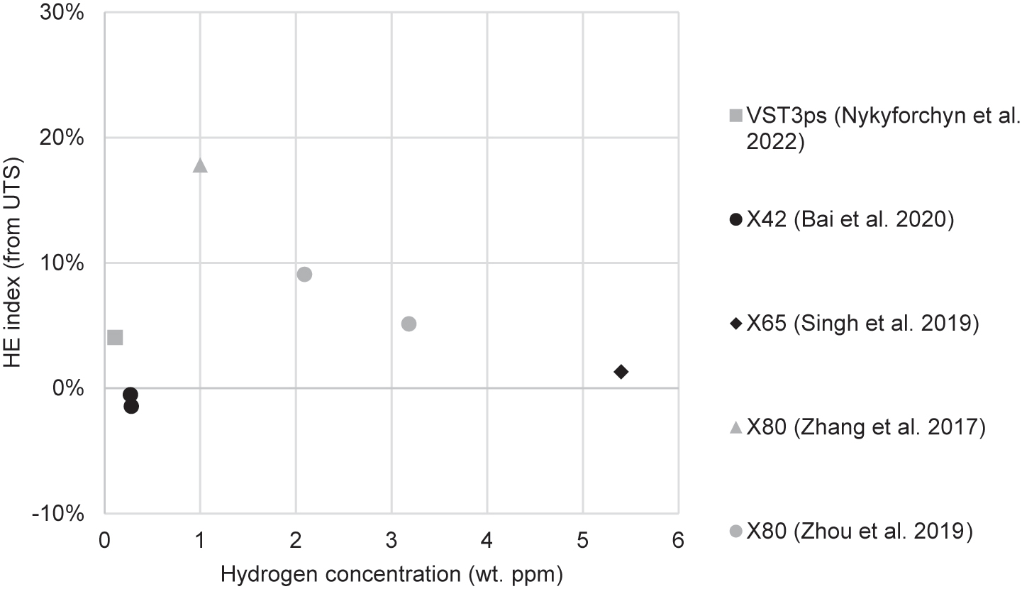
Percentage reduction in UTS in electrochemical studies that evaluated the internal hydrogen concentration. A negative HE index value indicates that UTS was increased after hydrogen charging.
It has been proposed that relatively low hydrogen concentrations generated by gaseous charging reduce steel strength, while the higher concentrations typically generated by electrochemical charging increase strength (Zhao et al. 2015). The data shown in Figures 16 and 17 instead support the opposite, that low hydrogen concentrations can increase strength while high hydrogen concentrations reduce strength, as a greater number of studies of gaseous hydrogen charging found hydrogen strengthened the steel (as evidenced by a negative HE index). Meng et al. (2017), studying X80, and Nanninga et al. (2012), studying X100, both found that UTS was increased by exposure to low hydrogen partial pressures below 10 bar. Zhang et al. (2017b) found that X80 electrochemically charged with 1 wt ppm hydrogen had UTS reduced by 18%.
Xu (2012) concluded from a literature review that HELP was the dominant HE mechanism in low-carbon steels. Moro et al. (2010) instead considered HEDE the primary mechanism of embrittlement for X80. They observed interfaces between layers of ferrite and pearlite in the fracture surface of the rolled steel, and proposed that hydrogen transported by dislocations had accumulated at these interfaces and caused HE by decohesion. Han et al. (2019) indicated that HE was caused by HELP at low hydrogen concentrations in X100, which was evidenced by a reduction in the YS of the steel, while they proposed a mixture of HELP and HEDE caused HE at higher concentrations, where HEDE was evidenced by secondary cracks on the fracture surfaces.
5.4.1 Tensile properties of welds
There has been limited research into the tensile properties of pipeline welds in hydrogen gas. Nguyen et al. (2020c) found that the strength of X70 weld metal was unaffected by hydrogen, but ductility was reduced, with elongation decreasing from approximately 26% in air to 21%, and reduction in area decreasing from approximately 70% in air to 50%. The specimens were exposed to a gas mixture of 1 bar hydrogen and 99 bar methane. The ductility of the base metal was unaffected by hydrogen. These results indicated that these pipeline welds were more susceptible to HE than the base metal. The authors used SEM to analyse the fracture surfaces. The weld specimen fractured in air underwent ductile failure and the surface contained MVC dimples. After hydrogen charging, there was less necking. The fracture surface was split between a brittle region at the surface (the region expected to have higher hydrogen content) showing evidence of quasi-cleavage fracture and a central ductile region. There were surface cracks in the necking region, which in some specimens were parallel to the fracture surface, while in others were at a 45° angle to the fracture surface. The possible causes for the different crack orientations were not fully explored.
The welds were girth pipe welds created by orbital welding. The microstructures of the base and weld metal are shown in Figure 18. The X70 base metal microstructure was ferritic, consisting mostly of acicular and polygonal ferrite. The weld metal had a less uniform microstructure, with interspersed sections of dendritic ferrite and bainite as well as various inclusions (Nguyen et al. 2020c).
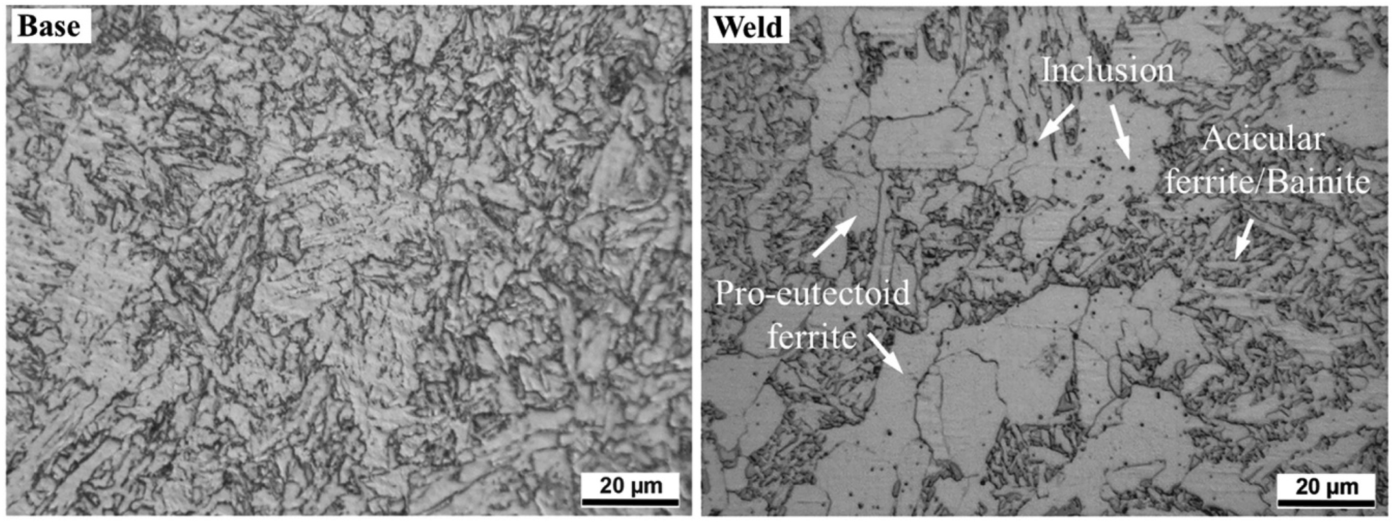
Microstructures of X70 steel base metal and weld metal. Reproduced from Nguyen et al. (2020c) with permission.
To explain the reduced hydrogen tolerance in the weld, Nguyen et al. (2020c) proposed several contributing microstructural differences: (i) the more homogeneous microstructure of the base metal allowed hydrogen to uniformly diffuse and not become concentrated at crack initiation sites; (ii) acicular ferrite (in the base metal) contains more hydrogen traps than bainite, as reported by Park et al. (2008), and these traps reduced the amount of diffusible hydrogen which was responsible for HE; (iii) the alternating dendritic ferrite and bainite in the weld metal led to differences in hardness which can localise strain, leading to hydrogen concentration and crack initiation; and (iv) inclusions in the weld metal served as hydrogen concentration sites and therefore crack initiation sites.
Nguyen et al. (2021) produced similar results in a subsequent study of notched tensile specimens: the X70 base metal was unaffected by hydrogen but the weld was embrittled. The stress concentration in the notched tensile specimens correlated with increased HE, and base metal and weld metal were similarly affected by the stress concentration.
Boot et al. (2021) found that notched, hollow X60 base metal specimens in 100 bar hydrogen had an I value (as measured from reduction in area) of 28%, while the weld specimens had an I of 11%. These results show that, despite the weld being stronger and more brittle, the base metal was more susceptible to hydrogen than the weld. The YS and UTS of the base metal or weld were unaffected by hydrogen. Reducing the tested hydrogen pressure from 100 bar to 30 bar produced no change in the ductility, suggesting saturation occurred at a hydrogen pressure below 30 bar.
Figure 19 summarises the reduction in ductility in the pipeline weld tensile studies. Nguyen et al. (2020c) found that the weld material was more susceptible to HE than the base metal, while Boot et al. (2021) found the base metal was more susceptible to HE than the weld. More studies are required to reconcile this inconsistency. Figure 20 shows that hydrogen had a negligible effect on UTS in both the weld metal and the base metal.
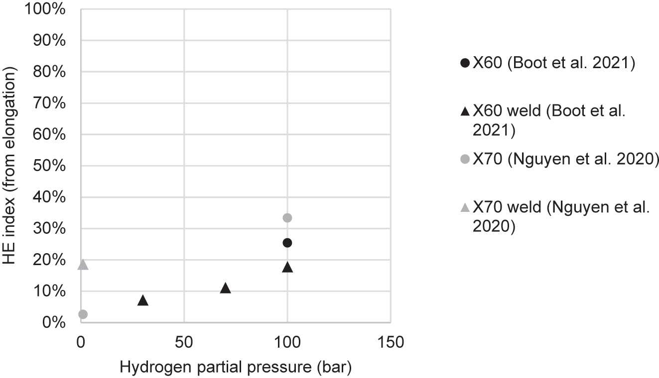
HE index resulting from hydrogen partial pressure in tensile studies of pipeline steel welds. HE index is calculated from elongation at fracture.
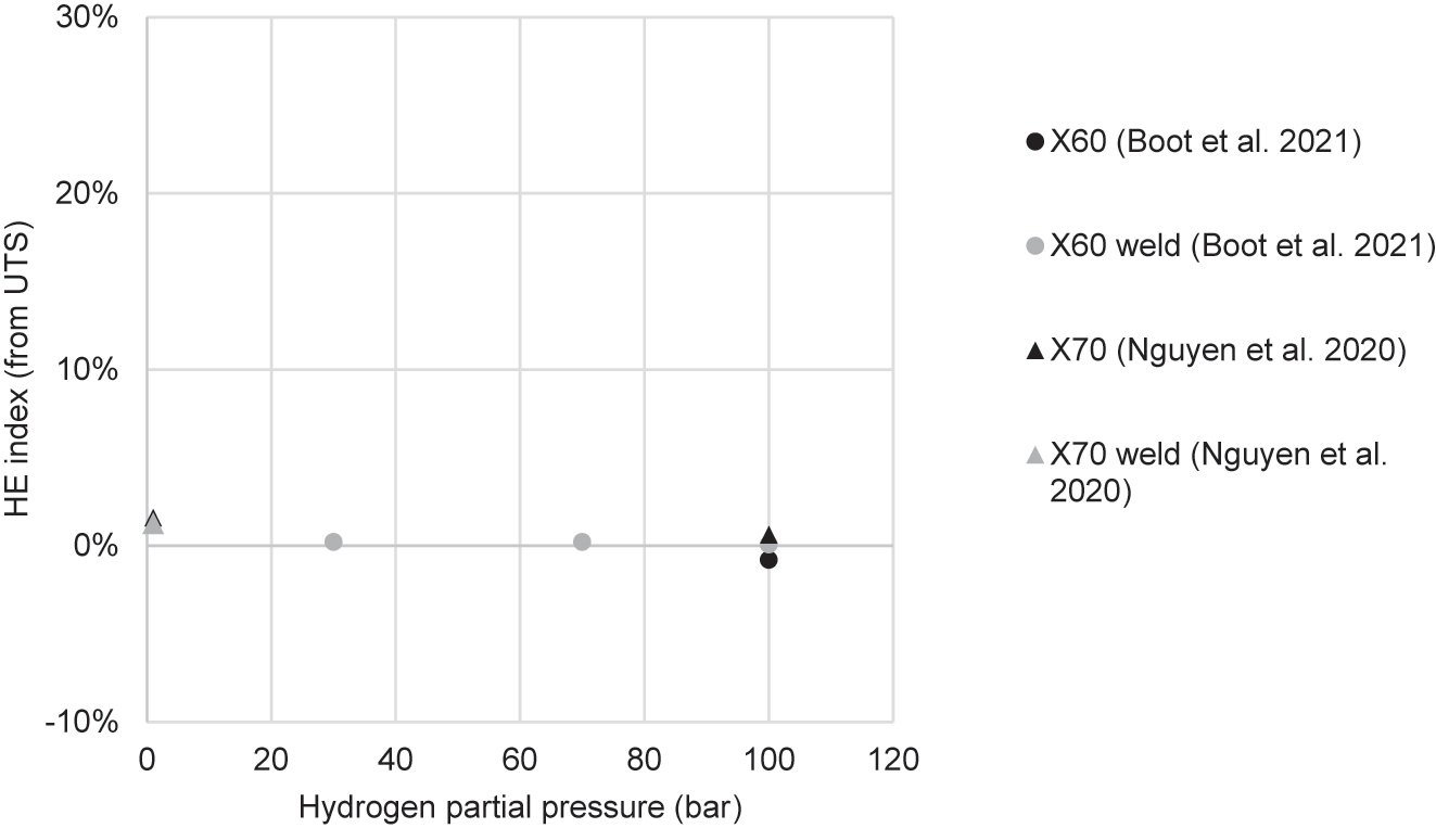
Percentage reduction of the UTS in base metal and weld metal. A negative HE index value indicates that UTS was increased by hydrogen charging.
5.5 Permeation experiments
Table 4 summarises the experimental conditions used in electrochemical permeation experiments in pipeline steels. All studies used the Devanathan-Stachurski cell design discussed in Section 4.2. The most frequently researched pipeline steels were X70 and X80, with some studies on X65, X100 and F22 steels. As with the tensile experiments discussed in Section 5.4, the most frequently used electrolyte for hydrogen generation was sulfuric acid (H2SO4). Recombination poisons were used frequently; commonly used poisons included arsenic trioxide (As2O3), thiourea (SC(NH2)2), and sodium sulphide (Na2S·9H2O).
Summary of experimental conditions used in permeation experiments of pipeline steels.
| References | Steel grade | Temperature (°C) | Specimen thickness (mm) | Variables | Cathodic compartment | Anodic compartment | ||
|---|---|---|---|---|---|---|---|---|
| Electrolyte | Current/Potential | Electrolyte | Potential | |||||
| Torres-Islas et al. (2005) | X70 | 50 | 0.7 | Heat treatment | 0.1, 0.05, 0.01 and 0.005 M NaHCO3 | Not disclosed | 0.1 M NaOH | +250 mV (SCE) |
| Dey et al. (2006) | X65 | 25 | 0.42, 0.66, 0.88 | Thickness | 1 N H2SO4 + 10 mg/L NaAsO2 | OCP | 1 N NaOH | −100 mV (SCE) |
| Dong et al. (2009a) | X70 | 25 | 0.77 | – | 0.5 M H2SO4 + 250 mg/L As2O3 | 0.5 mA/cm2 | 0.1 M NaOH | +300 mV (SCE) |
| Dong et al. (2009b) | X100 | 25 | 0.542 | – | 0.5 M H2SO4 + 250 mg/L As2O3 | 10 mA/cm2 | 0.1 M NaOH | +300 mV (SCE) |
| Torres-Islas and Gonzalez-Rodriguez (2009) | X70 | 50 | 0.5 | Electrolyte concentration, heat treatment (quenching) | 0.1, 0.05, 0.01 and 0.005 M NaHCO3 | Not disclosed | 0.5 M NaOH | +300 mV (SCE) |
| Dong et al. (2010) | X80 | 25 | 0.56 | – | 0.5 M H2SO4 + 250 mg/L As2O3 | 10 mA/cm2 | 0.1 M NaOH | +300 mV (SCE) |
| Skjellerudsveen et al. (2010) | X70 (weld and HAZ) | 25, 50, 70 | 1.04, 1.97, 2.06 | Temperature, location (BM, weld & HAZ) | 0.1 M NaOH | −1050 mV (Ag/AgCl) | 0.1 M NaOH | +350 mV (Ag/AgCl) |
| Xue and Cheng (2011) | X80 | 25 | 0.5 | – | 0.5 M H2SO4 | 10 mA/cm2 | 0.1 M NaOH | +200 mV (SCE) |
| Fallahmohammadi et al. (2012) | X65, F22 | 20 | 1, 2 | Apparent and lattice diffusivities | 0.4 M CH3COOH + 0.2 M CH3COONa | 0.5–1 mA/cm2 | 0.2 M NaOH | +100 mV (Ag/AgCl) |
| Zhang et al. (2012) | X70 | 8, 20 | 0.5 | Temperature, applied potential | Seawater | −850 to −1050 mV (Hg/HgO?) | 0.2 M NaOH | +150 mV (Hg/HgO) |
| Fallahmohammadi et al. (2013) | X65, F22 | 20 | Not disclosed | Apparent and lattice diffusivities | 0.2 M CH3COOH + 0.4 M CH3COONa | 0.5–1 mA/cm2 | 0.2 M NaOH | +100 mV (Ag/AgCl) |
| Haq et al. (2013) | X70 | 22 | 1 | Region of pipe | 0.1 N NaOH + 10 g/L Na2S·9H2O | 3.52 mA/cm2 | 0.1 N NaOH | Not disclosed |
| Liu et al. (2013) | X80 | 4 | 0.2 | Applied potential | Seawater | −850 to −1200 mV (Hg/HgO?) | 0.2 M NaOH | +150 mV (Hg/HgO) |
| Xue and Cheng (2013) | X80 (weld and HAZ) | 25 | 0.5 | Location (BM, weld & HAZ) | 0.5 M H2SO4 | 10 mA/cm2 | 0.1 M NaOH | +200 mV (SCE) |
| Fallahmohammadi et al. (2014) | X65, F22 | 20 | 1.3 | Heat treatment (annealing, quenching, quenching and tempering) | 0.4 M CH3COOH + 0.2 M CH3COONa | 0.5–1 mA/cm2 | 0.2 M NaOH | +100 mV (Ag/AgCl) |
| Ha et al. (2014) | X70 | 25 | Not disclosed | Prior cold work | Not disclosed | Not disclosed | Not disclosed | Not disclosed |
| Huang et al. (2014) | X80 | 25–60 | 1.2 | Temperature | Not disclosed | Not disclosed | Not disclosed | Not disclosed |
| Mohtadi-Bonab et al. (2014) | X70 | 25 | 1 | Heat treatment (quenching, water-spraying, quenching and tempering) | 0.1 M H2SO4 + 3 g/l NH4SCN | 5 mA (Unspecified area) | 0.1 M NaOH | Not disclosed |
| Zhang et al. (2017a) | X80 | 20–30 | 0.7 | Temperature, applied current | 0.5 M H2SO4 + 0.2 g/L SC(NH2)2 | 0.1–40 mA/cm2 | 0.1 M NaOH | +300 mV (SCE) |
| Han et al. (2019) | X100 | 25 | 0.6 | Pre-strain | 0.5 M H2SO4 + 0.5 g/L SC(NH2)2 | 5 mA/cm2 | 0.1 M NaOH | +300 mV (SCE) |
| Liu et al. (2019) | X65 | 25–60 | 1 | Temperature, applied potential | 3.5 vol% NaCl | −800 to −1200 mV (SCE) | 0.2 M NaOH | +200 mV (SCE) |
| Zhang et al. (2019) | X80 | 25 | 1 | Niobium contents | 0.5 M H2SO4 + 3 g/L SC(NH2)2 | 2 mA/cm2 | 0.2 M NaOH | +300 mV (SCE) |
| Zhou et al. (2019) | X80 | 25–45 | 1 | Temperature, heat treatment (annealing) | 0.5 M H2SO4 + 2 g/L SC(NH2)2 | 5 mA/cm2 | 0.1 M NaOH | +100 mV (SCE) |
| Li et al. (2020a) | X80 | 25 | 1 | Finish rolling deformation | 0.5 vol% CH3COOH + 3.5 wt% NaCl + 1 g/L Na2S·9H2O | 0.05 mA/cm2 | 0.1 M NaOH | +160 mV (SCE) |
| Li et al. (2020b) | X80 | 25 | 1 | Heat treatment (tempering) | 0.5 vol% CH3COOH + 3.5 wt% NaCl + 1 g/L Na2S·9H2O | 0.05 mA/cm2 | 0.1 M NaOH | +160 mV (SCE) |
| Thomas and Szpunar (2021) | X70 | 25 | 1 | Cold rolling | 0.1 M H2SO4 + 3 g/L NH4SCN | 5 mA (Unspecified area) | 0.1 M NaOH | +250 mV (SCE) |
-
The variables column shows what parameters were varied across the studies. No entry in the variables column means the experimental conditions were the same throughout the study. The cathodic and anodic compartments are the entry and exit compartments in the Devanathan-Stachurski cell. The brackets after potentials show the reference electrode.
Table 5 summarises the effective diffusivities from the permeation studies. Diffusivities were most frequently calculated from the time lag method. Table 5 indicates that there may be a general relationship between decreasing diffusivity and increasing strength. This trend is highlighted by Figure 21. Figure 21 shows that the hydrogen diffusivities varied greatly within steel grades. For example, the hydrogen diffusivities found by studies of X80 varied from 5.3 × 10⁻⁹ to 9.8 × 10⁻⁵ cm2/s.
Summary of hydrogen diffusivities from permeation studies of pipeline steels.
| Steel grade | Number of included results | Geometric mean diffusivity (cm2/s) | Geometric standard deviation (cm2/s) |
|---|---|---|---|
| F22 | 2 | 3.74 × 10⁻⁶ | 1.10 |
| X65 | 3 | 1.47 × 10⁻⁶ | 1.52 |
| X70 | 20 | 8.08 × 10⁻⁷ | 3.25 |
| X80 | 19 | 2.94 × 10⁻⁶ | 9.87 |
| X100 | 2 | 7.53 × 10⁻⁸ | 16.44 |
-
Geometric mean and geometric standard deviation were used because the data span multiple orders of magnitude. The included data were limited to studies conducted at approximately room temperature (between 20 and 25 °C).
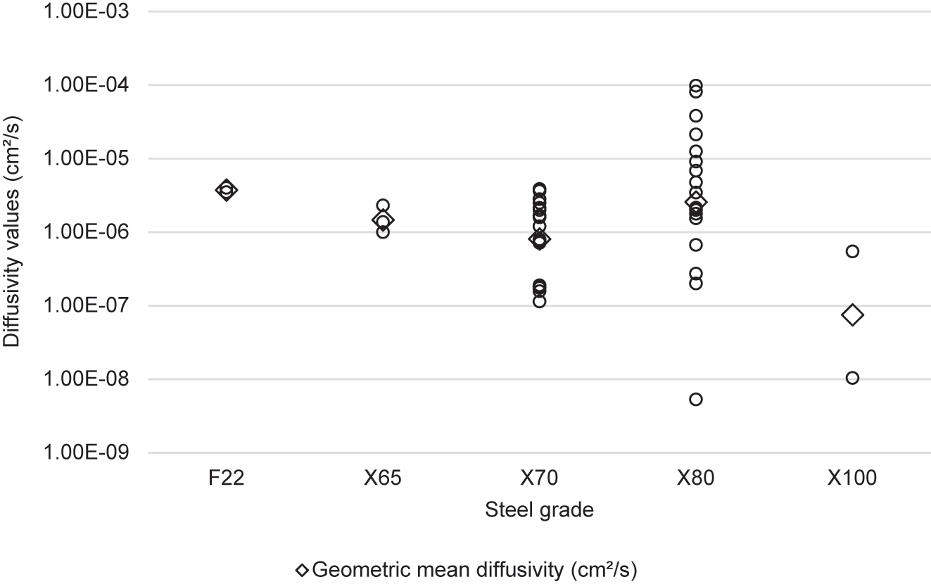
Values of hydrogen diffusivity in permeation studies grouped by steel grade. The geometric mean diffusivity for each steel grade is shown by a diamond.
Numerous researchers investigated the influence of heat treatment on hydrogen permeation. Torres-Islas et al. (2005) found that three heat treatments of X70 all increased the hydrogen permeation flux significantly, with the largest permeation flux after quenching, then quenching and tempering, then water-spraying. The researchers did not calculate the hydrogen diffusivities or hydrogen concentrations. Fallahmohammadi et al. (2014) found that the hydrogen diffusivities of X65 were highest when annealed at 930 °C (2.0 × 10⁻⁵ cm2/s), followed by quenched and tempered (4.7 × 10⁻⁶ cm2/s), and quenched from 930 °C (1.4 × 10⁻⁶ cm2/s). They found that the hydrogen concentration increased as the diffusivity decreased (attributed to increased trapping). Mohtadi-Bonab et al. (2014) evaluated the effective diffusivities (which includes the effect of trapping), with the highest diffusion coefficient in the as-received steel (3.9 × 10⁻⁶ cm2/s), followed by water-sprayed from 850 °C (2.9 × 10⁻⁶ cm2/s), tempered at 350 °C (2.6 × 10⁻⁶ cm2/s), and quenched from 850 °C (2.2 × 10⁻⁶ cm2/s). They also found that the hydrogen concentration had an inverse relationship with diffusivity. Zhou et al. (2019) found that heat treating X80 at 200 °C increased diffusivity by ∼65%. Li et al. (2020b) varied the tempering temperature of an X80 steel from 450 °C to 700 °C, finding that increasing tempering temperature reduced the diffusivity and increased the hydrogen concentration. The available heat treatment research indicated that annealed pipeline steels had significantly higher diffusivities, and quenched steels had the lowest diffusivities.
Other researchers have investigated the influence of deformation on hydrogen permeation. Li et al. (2020a) found that the diffusivity increased slightly with increased compression ratio of finish rolling from 20% to 50% of X80, but there was little influence on hydrogen solubility. Thomas and Szpunar (2021) found for X70 increasing the degree of cold rolling from 0 to 80% lowered the effective diffusivity from 2.5 × 10⁻⁶ to 1.1 × 10⁻⁷ cm2/s, and the lattice diffusivity from 3.3 × 10⁻⁶ to 4.2 × 10⁻⁷ cm2/s, attributed to the significantly increased number of traps.
Figure 22 shows that most studies have found that hydrogen diffusivity increased with increasing temperature. The one exception was Liu et al. (2019) who found a decrease of diffusivity with increasing temperature for an X65 steel, ascribed by the authors to a high hydrogen concentration producing voids, which impeded hydrogen diffusion. However, most studies (as indicated in Figure 22) have found increasing diffusivity with increasing temperature attributed to the increased temperature providing more energy for the elemental jumps of the hydrogen atom which is the basis of hydrogen diffusion.
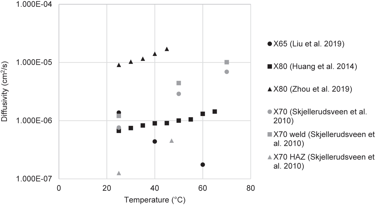
Hydrogen diffusivity typically increases with increasing temperature in permeation studies of pipeline steels. The data indicate no general tendency with steel strength.
Two papers have investigated hydrogen permeation in the weld and HAZ of pipeline steels. Skjellerudsveen et al. (2010) found the diffusivity in the weld averaged ∼150% of the X70 base metal. The HAZ had the smallest diffusivity, averaging ∼16% of the base metal. The hydrogen concentrations in the base metal, weld and HAZ averaged 0.27, 0.08 and 1.05 ppm, respectively. In contrast, Xue and Cheng (2013) found in X80 that the base metal had the highest diffusivity, followed by the weld metal, then the HAZ. The weld had a similar hydrogen concentration as the HAZ. The authors also evaluated the number of traps, finding that the HAZ had the highest number of traps, followed by the weld, then the base metal.
Table 6 gives results for subsurface hydrogen concentrations in studies that gave details on the applied current or potential. Figure 23 shows that there was no clear relationship between current density and concentration across the permeation studies. This variation may be attributed to differences in charging conditions and differences in steel processing greatly influencing the number of traps. There was a significant degree of variation in the hydrogen concentrations, with the majority ranging from 0.029 to 197 wt ppm. Li et al. (2020a, 2020b) found that the hydrogen concentration varied from 0.62 to 6.3 wt ppm in X80 depending on heat treatment and amount of rolling reduction. Dong et al. found a hydrogen concentration of 197 wt ppm in X70 Dong et al. (2010) and 34.3 wt ppm in X100 (Dong et al. 2009b) steels using the same electrolyte and current density as in Li et al. (2020a). This may suggest that more hydrogen is generated at the surface of X70 steels than X100 steels, or it may be due to variations in the processing of these steels. An anomalously low concentration of 1.06 × 10⁻⁷ wt ppm was reported by Liu et al. (2019), which is assumed to be an error, which is supported by the reported anomalous diffusivities in this paper.
Subsurface hydrogen concentrations resulting from permeation experiments.
| References | Steel grade | Temperature (°C) | Electrolyte | Current density/Potential | Geometric mean hydrogen concentration (wt ppm) |
|---|---|---|---|---|---|
| Liu et al. (2019) | X65 | 25 | 3.5 vol% NaCl | −990 mV (SCE) | 1.06 × 10⁻⁷ |
| Dong et al. (2010) | X70 | 25 | 0.5 M H2SO4 + 0.25 g/L As2O3 | 10 mA/cm2 | 197 |
| Skjellerudsveen et al. (2010) | X70 | 25 | 0.1 M NaOH | −1050 mV (Ag/AgCl) | 0.56 |
| X70 weld | 0.22 | ||||
| X70 HAZ | 1.91 | ||||
| Haq et al. (2013) | X70 | 22 | 0.1 N NaOH + 10 g/L Na2S·9H2O | 3.52 mA/cm2 | 0.17 |
| Mohtadi-Bonab et al. (2014) | X70 | 25 | 0.1 M H2SO4 + 3 g/L NH4SCN | 5 mA (unspecified area) | 2.5 |
| Xue and Cheng (2011) | X80 | 25 | 0.5 M H2SO4 | 10 mA/cm2 | 6.7 |
| Xue and Cheng (2013) | X80 | 25 | 0.5 M H2SO4 | 10 mA/cm2 | 4.46 |
| X80 weld | 4.28 | ||||
| X80 HAZ | 3.10 | ||||
| Zhang et al. (2017a) | X80 | 20 | 0.5 M H2SO4 + 0.2 g/L CS(NH2)2 | 0.1 mA/cm2 | 0.09 |
| 0.2 mA/cm2 | 0.13 | ||||
| 1 mA/cm2 | 0.30 | ||||
| 5 mA/cm2 | 0.60 | ||||
| 10 mA/cm2 | 0.64 | ||||
| 20 mA/cm2 | 0.65 | ||||
| 30 mA/cm2 | 0.63 | ||||
| 40 mA/cm2 | 0.63 | ||||
| Zhang et al. (2019) | X80 | 25 | 0.5 M H2SO4 + 3 g/L CS(NH2)2 | 2 mA/cm2 | 0.12 |
| Li et al. (2020a) | X80 | 25 | 0.5 vol% CH3COOH + 3.5 wt% NaCl + 1 g/L Na2S·9H2O | 0.05 mA/cm2 | 5.89 |
| Li et al. (2020b) | X80 | 25 | 0.5 vol% CH3COOH + 3.5 wt% NaCl + 1 g/L Na2S·9H2O | 0.05 mA/cm2 | 1.48 |
| Dong et al. (2009b) | X100 | 25 | 0.5 M H2SO4 + 0.25 g/L As2O3 | 10 mA/cm2 | 34.3 |
| Han et al. (2019) | X100 | 25 | 0.5 M H2SO4 + 0.5 g/L CS(NH2)2 | 5 mA/cm2 | 20.2 |
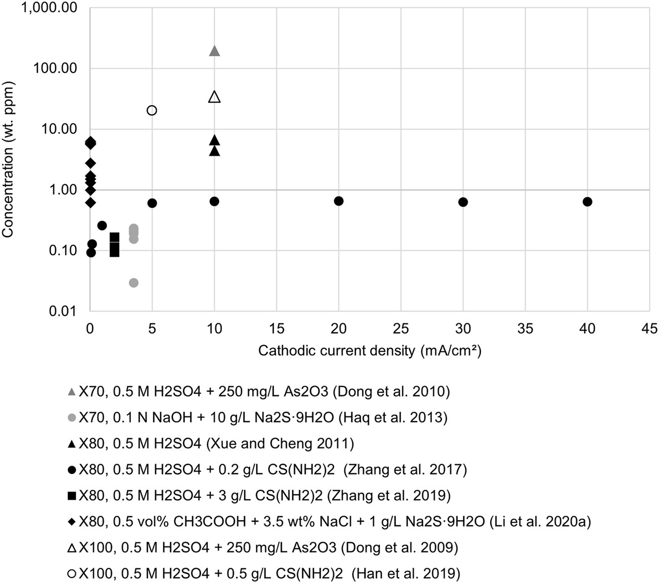
Subsurface hydrogen concentration resulting from applied current density in permeation studies of pipeline steels. The legend denotes the steel grade, electrolyte used, and reference number. Details on the concentrations are given in Table 6.
Studies of gaseous hydrogen permeation are rare, and no studies of gaseous permeation in pipeline steels were found in this literature review. For this reason, the relationship between hydrogen gas pressure and subsurface concentration for pipeline steels could not be evaluated. The equivalent fugacity resulting from cathodic overpotential (discussed in Section 4.2) for pipeline steels has also not been evaluated.
5.6 Fracture toughness
Table 7 tabulates the effect of hydrogen on the fracture toughness of pipeline steels. Only studies that included results for fracture toughness in air are included so that results can be compared by the hydrogen embrittlement index, IFM. IFM can be calculated from numerous fracture parameters including the stress intensity factor (K), the J-integral, and the crack-tip opening displacement (CTOD) at fracture. The IFM values listed in Table 7 are based on the reported fracture parameters. The specimen orientation uses the two-letter codes defined in ASTM E399 (ASTM International 2020). The first letter defines the direction perpendicular to the crack plane (which is also typically the longest dimension of the specimen). The second letter defines the direction of crack propagation. The directions are L for longitudinal, T for transverse, and S for short transverse (pointing into the pipe wall). For example, LS designates a specimen cut from the longitudinal plane with the notch directed into the pipe wall.
Summary of fracture toughness studies of HE in pipeline steels.
| References | Steel grade | Specimen type | Orientation | IHE/HEE | Hydrogen delivery | Charging conditions | Fracture toughness (K) (MPa |
Hydrogen embrittlement index (IFM) | |
|---|---|---|---|---|---|---|---|---|---|
| In air | In H2 | ||||||||
| Andrews et al. (2001) | X80 | Three-point bending (TPB) | LT | HEE | Electrolytic: NS4 simulated soil | −1.5 V (CSE) | Not disclosed | Not disclosed | (From CTOD) 76% |
| Wang (2009) | X70 | Single edge notch tension (SENT) | N/A – cut from sheet | HEE | Electrolytic: 0.5 M H2SO4 | 1–100 mA/cm2 | (KIQ) 91 |
At 1 mA/cm2: 71 10 mA/cm2: 63 100 mA/cm2: 51 |
(From KIQ) 10 mA/cm2: 30% 100 mA/cm2: 42% |
| Chatzidouros et al. (2011) | X52, X70, base metal and HAZ | TPB | TS | HEE | Electrolytic: NS4 simulated soil | 1, 5, 10 mA/cm2 | (KQ) X52 BM: 45 X52 HAZ: 46 X70 BM: 64 X70 HAZ: 70 |
At 10 mA/cm2: X52 BM: 44 X52 HAZ: 49 X70 BM: 66 X70 HAZ: 65 |
(From J-integral) at 10 mA/cm2, X52 BM: 51% X52 HAZ: 33% X70 BM: 63% X70 HAZ: 34% |
| Hejazi et al. (2012) | X70, base metal and HAZ | TPB | N/A – Cut from sheet | IHE | Electrolytic: 0.5 N H2SO4 + 0.25 g/L NaAsO2 | 50 mA/cm2 for 20, 90 min | Not disclosed | Not disclosed | (From J-integral) Base metal 2 ppm: 15% Base metal 4 ppm: 36% HAZ 2 ppm: 29% HAZ 4 ppm: 69% |
| Chatzidouros et al. (2014) | X65 | TPB | TS | HEE | Electrolytic: NS4 simulated soil | 1, 5, 10 mA/cm2 | (KQ) 47 |
At 1 mA/cm2: 49 5 mA/cm2: 52 10 mA/cm2: 51 |
(From J-integral) 1 mA/cm2: 78% 5 mA/cm2: 83% 10 mA/cm2: 85% |
| Chatzidouros et al. (2018) | X65 | TPB | TL & SL | IHE | Electrolytic: 30 g/L NaCl + 3 g/L NH4SCN | 0.5–2 mA/cm2 for 48 h | (KQ) 51 |
At 0.5 ppm: 51 1 ppm: 51 2 ppm: 50 |
(From KQ) 0.5 mA/cm2: −0.8% 1 mA/cm2: −1.2% 2 mA/cm2: 0.0% |
| Li et al. (2018) | X90 | SENT | LT | IHE | Electrolytic: 0.5 N H2SO4 + 3 g/L NH4SCN | 10 mA/cm2 for 4 h | Not disclosed | Not disclosed | (From CTOD) 0.5 B/W: 66% 1 B/W: 81% 2 B/W: 91% |
| Cabrini et al. (2019) | X70SS, X80, X100 | TPB | Not disclosed | HEE | Electrolytic: 3.5 vol% NaCl | OCP, −1 V, −2 V (SCE) | Not disclosed | Not disclosed | (From J-integral) at −2 V X70SS: 89% X80: 68% X100: 82% |
| Kyriakopoulou et al. (2020a) | X65, base metal and weld | TPB | Not disclosed | IHE | Electrolytic: 30 g/L NaCl + 3 g/L NH4SCN | 10, 20, 30 mA/cm2 for 48 h | (KQ) BM: 34 Weld: 31 |
At 10 mA/cm2: BM: 31 Weld: 26 |
(From KQ) at 30 mA/cm2 Base metal: 34% Weld: 41% |
| Kyriakopoulou et al. (2020b) | X65 | TPB | Not disclosed | HEE | Electrolytic: 0.2 M NaCl + 3 g/L NH4SCN | 10, 20 mA/cm2 | (KQ) 42 |
10 mA/cm2: 35 20 mA/cm2: 30 |
(From KQ) 10 mA/cm2: 17% 20 mA/cm2: 29% |
| Nguyen et al. (2020a) | X70 | CT | TL | HEE | Gaseous: H2 and CH4; and pure H2 | 1 bar H2, 99 bar CH4; 100 bar H2 | Not disclosed | Not disclosed | (From CTOD) H2 and CH4: 49% Pure H2: 70% |
-
Studies that did not conduct a test in air were not included. Orientation uses two letter codes defined in ASTM E399 (ASTM International 2020). The type of fracture toughness calculated (for example, KIC, or KQ) is given in the fracture toughness in air column.
Li et al. (2018) found that hydrogen significantly reduced the crack tip opening displacement (CTOD) for all specimens tested, which were single edge notch tensile (SENT) specimens. IFM increased significantly as the thickness-to-width ratio was increased, from 66% at a thickness-to-width ratio of 0.5 to 91% at a ratio of 2. This indicates that the influence of hydrogen on fracture toughness in this case depends upon the specimen dimensions.
Hardie et al. (2006), using tensile specimens, found that hydrogen embrittlement saturation appeared at 10 mA/cm2 as HE did not increase beyond this point. In contrast, Wang (2009) and Kyriakopoulou et al. (2020a) found that fracture toughness was further reduced at higher currents up to 100 mA/cm2, which was the maximum current tested (Wang 2009). Kyriakopoulou et al. (2020a) found fracture toughness was reduced up to the maximum current tested, 30 mA/cm2, and the number of blisters increased with current density above 10 mA/cm2, indicating that these applied current densities were producing hydrogen fugacities greater than the strength of the steel and were directly damaging the steel.
Nguyen et al. (2020a) found that the fracture toughness measured with compact tension (CT) specimens was reduced by 30% in a gaseous environment of 1 bar hydrogen and 99 bar methane. This indicates that small amounts of hydrogen in natural gas pipelines (whether sourced from methane enrichment or electrochemical processes such as cathodic protection) can significantly reduce fracture toughness. This contrasts with the tensile results in the same environment given in the same article, where this hydrogen partial pressure only negligibly reduced the ductility.
Generally, the hydrogen embrittlement index (I) values evaluation using the fracture toughness studies were greater than those evaluated using ductility from the tensile studies in Table 2, indicating that hydrogen affects fracture properties more than ductility in pipeline steels. For example, Cabrini et al. (2019) using the same electrolytic hydrogen charging solution found that (i) at the open circuit potential the fracture toughness of X70, X80, and X100 was reduced by 13–42%, whereas there was no reduction in ductility in the tensile tests, and (ii) at an applied potential of −2 V the fracture toughness was reduced significantly (68–89%) compared with a lower reduction in the reduction in area (37–48%) in the tensile tests. Nguyen et al. (2020a) found for X70 in gaseous hydrogen that (i) at 1 bar hydrogen, the RA in the tensile tests was reduced by 3% while the fracture toughness was reduced by 30%, and (ii) at 100 bar hydrogen, RA was reduced by 33% and fracture toughness was reduced by 49%.
Table 7 indicates that most studies found hydrogen reduced fracture toughness significantly, indicating that pipeline steels are susceptible to hydrogen induced fracture. The single anomalous article was that by Chatzidouros et al. (2018) which found that (i) the stress intensity factor (KQ) was unaffected by the hydrogen concentration for pre-charged specimens, but (ii) the CTOD was significantly reduced by 33% for 0.5 ppm hydrogen, 78% ppm for 1 ppm hydrogen, and 82% for 2 ppm hydrogen. The inconsistencies in these results could be because the specimens were pre-charged as it was found by Wang (2009) that pre-charging could produce inconsistent results. However, similar results were found in the other fracture toughness studies by Chatzidouros et al. (2011), (2014) which featured in-situ charging: the fracture parameter KQ was also unaffected by hydrogen, while other fracture toughness parameters, such as the J-integral, were reduced by hydrogen.
This may indicate that KQ is not affected by hydrogen in three-point bending (TPB) tests. In contrast, Kyriakopoulou et al. (2020a), (2020b) found that KQ was significantly reduced by hydrogen in similar TPB tests on X65 charged in-situ at 10 mA/cm2. Kyriakopoulou et al. (2020b) found the J-integral was reduced by 28%, and KQ was reduced by 17%. Chatzidouros et al. (2014) found the J-integral was reduced by 85% in the hydrogen charged-specimens, whereas KQ actually increased by 9%. In two of their studies, Chatzidouros et al. (2018) and Kyriakopoulou et al. (2020a) used identical electrolytes yet still found conflicting results for the effect of hydrogen on KQ. This discrepancy may indicate that the two groups used different methods for calculating KQ.
Figure 24 shows the influence of the hydrogen concentrations on the hydrogen embrittlement index based on the fracture toughness. The irregular results from Chatzidouros et al. (2018) are included. The results for X70 from Wang (2009) and Hejazi et al. (2012) indicate that IFM varies from 15% to 42% at ∼2 wt ppm. This shows the variability of the measured effect of hydrogen on fracture toughness for similar pipeline steels. The results of Wang (full circles) indicate the hydrogen embrittlement index increases rapidly for small amounts of hydrogen, and thereafter increases more slowly. The results of Wang (2009) and Li et al. (2018) indicate high values of the hydrogen embrittlement index for high hydrogen concentrations of 2–2.5 wt ppm.
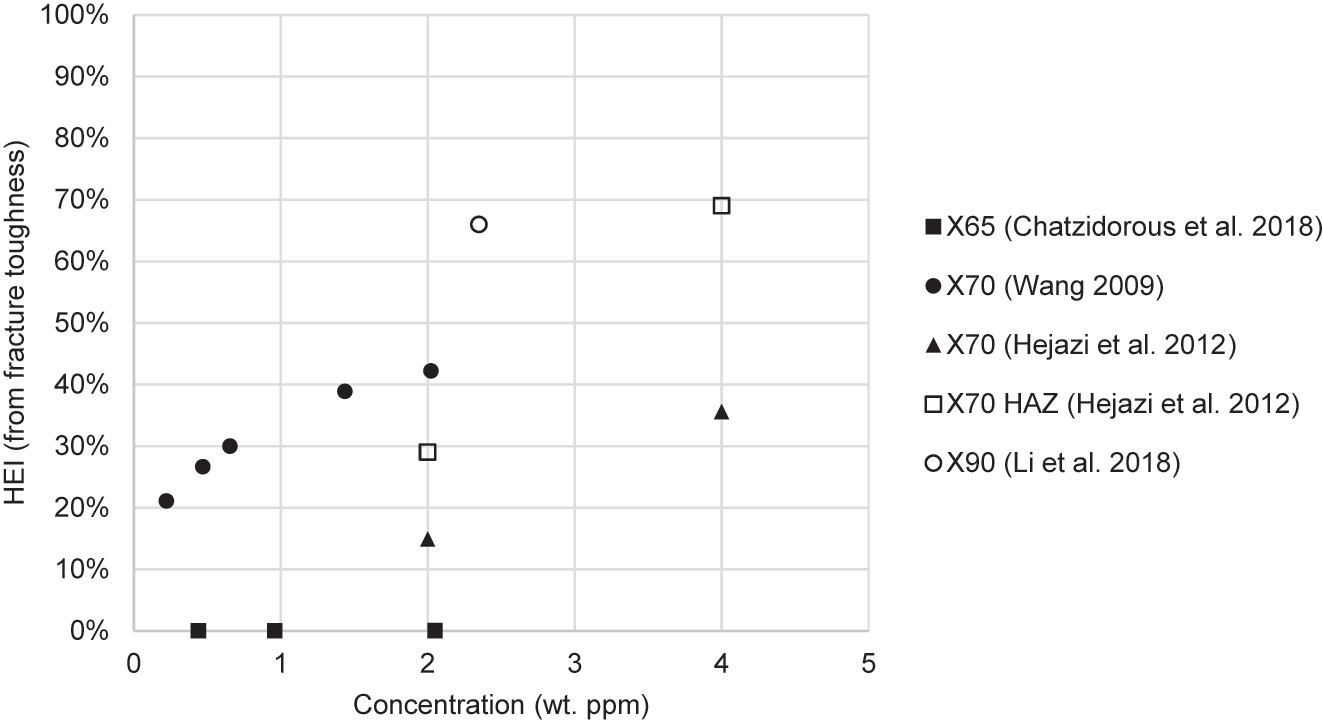
Influence of hydrogen concentration on the hydrogen embrittlement index evaluated from the fracture toughness for pipeline steels.
Hejazi et al. (2012) found that the simulated HAZ of X70 had a substantially higher hydrogen embrittlement index based on the fracture toughness than the base metal. In contrast, Chatzidouros et al. (2011) found that the hydrogen embrittlement index based on fracture toughness of the HAZ was less than that of the base metal. Kyriakopoulou et al. (2020a) found that for X65, hydrogen had a similar influence on the fracture toughness of the weld and base metal.
Chatzidouros et al. (2011) found that (i) the base of metal of X52 consisted of bands of alternating ferrite and pearlite, and (ii) the HAZ also consisted of alternating ferrite and pearlite but in a non-banded structure with varying grain sizes. Numerous authors have found that the microstructure of X65 steel typically consists of ferrite and bainite phases, with some islands of degenerated pearlite (Chatzidouros et al. 2014, 2018, Kyriakopoulou et al. 2020a, b). Hejazi et al. (2012) reported that an X70 consisted of ferrite and pearlite, while Nguyen et al. (2020a) (2020b), found an X70 consisted of bands of ferrite and bainite. Chatzidouros et al. (2011) found the HAZ of X70 had transformed some of the pearlite in the base metal into ferrite. Cabrini et al. (2019) found X80 was mostly bainite with some islands of ferrite, and X100 consisted of martensite and bainite.
Comparison of the IFM values of different steel grades or microstructures is made possible by studies that conducted experiments on multiple steel grades and used consistent testing procedures and fracture parameters. Chatzidouros et al. (2011) found that the X70 base metal (banded ferrite and bainite/pearlite) was slightly more susceptible to HE than the X52 base metal (banded ferrite and pearlite), whereas the IFM values of the two HAZs were similar. Cabrini et al. (2019) found no correlation between steel strength and IFM for X70, X80, and X100, with the X80 steel having the lowest IFM and the X70SS steel having the highest IFM. These two studies found no strong relationship between steel strength and IFM, suggesting that the influence of hydrogen on fracture toughness is not strongly related to pipeline steel grade (or microstructure).
Numerous studies found that fracture toughness specimens fractured in air showed ductile features such as dimples and microvoids. After hydrogen charging, specimens showed features indicative of quasi-cleavage, with a mixture of dimpled and cleavage regions (Hejazi et al. 2012; Kyriakopoulou et al. 2020a, b; Li et al. 2018; Nguyen et al. 2020a; Wang 2009). Dimples in hydrogen-charged specimens were smaller, shallower, and elongated (Hejazi et al. 2012; Kyriakopoulou et al. 2020a). At higher hydrogen concentrations, more of the fracture surface showed cleavage facets, with larger steps between facets (Hejazi et al. 2012; Wang 2009).
Wang (2009) reasoned that the HELP mechanism was responsible for HE in specimens with reduced dimple size, as HELP reduces the stress required for ductile fracture at the crack tip, leading to smaller dimples. Wang proposed that the HEDE mechanism was responsible for HE in specimens with brittle cleavage facets. Hejazi et al. (2012) investigated X70 with varying manganese content and came to the same conclusion. They stated that manganese content in steels impedes dislocation motion, restricting the HELP mechanism, and these steels, therefore, predominantly undergo HEDE and show cleavage surfaces.
6 Conclusions
There are numerous research articles on hydrogen embrittlement (HE) in pipeline steels. Common areas of research include hydrogen permeation, tensile properties, and fracture toughness. However, this review has found that there are still several unexplored questions in this field of research.
The relationship between hydrogen partial pressure and internal hydrogen concentration in pipeline steels has not been quantified. For this reason, the results of electrochemical hydrogen charging experiments cannot be equated to hydrogen partial pressures. This relationship could be researched by conducting gas-phase permeation experiments.
There have been few studies on HE in pipeline welds. Nguyen et al. (2020c), (2021) found that X70 weld metal was more susceptible to HE than the base metal, and that the weld underwent significant HE at 1 bar hydrogen partial pressure. In contrast, Boot et al. (2021) found that X60 weld metal was more resistant to HE than the base metal. More results are required to assess the HE susceptibility of the weld and HAZ, and whether these or the base metal are expected to be the points of failure in an embrittled pipeline. The influence of welding method and weld composition on HE is also unknown.
Heat treatment of pipeline steels has been found to affect hydrogen diffusivity, with annealing increasing diffusivity and quenching decreasing diffusivity. There is less research on the influence of heat treatment on HE resistance. Torres-Islas et al. (2005) found quenched X70 was significantly more susceptible to HE. Higher strength pipeline steels undergo quenching and controlled cooling during production, and these steels are generally more susceptible to HE. Heat treatment could be a method of controlling HE susceptibility in pipeline steels, but currently the relationship between heat treatment and HE is unknown.
HE has been found to occur in methane-hydrogen mixtures. Whether methane influences HE in pipeline steels has not been thoroughly investigated. In carbon dioxide-hydrogen mixtures, HE was reduced by increasing the partial pressure of carbon dioxide while the hydrogen partial pressure was kept constant (Xiong et al. 2015). Whether this is the case for methane-hydrogen mixtures has not been researched.
The existence of delayed failure in pipeline steels has not been evaluated. Delayed failure can be assessed by conducting a tensile experiment in a hydrogen environment and maintaining a load for a period of time. As delayed failure has been typically only found in higher-strength steels, it is hypothesised that delayed failure may not occur in pipeline steels, but this has not been verified in the literature.
Funding source: Future Fuels CRC
Award Identifier / Grant number: RP 3.1-10
-
Author contributions: All the authors have accepted responsibility for the entire content of this submitted manuscript and approved submission.
-
Research funding: This research has been supported by the Future Fuels Cooperative Research Centre research projects RP3.1-10 “Hydrogen embrittlement of pipeline steels, subcritical crack growth(formation) and critical crack growth (initiation)” and RP3.1-13 “Feasibility of the use of gas phase inhibition of hydrogen embrittlement in gas transmission pipelines carrying hydrogen”.
-
Conflicts of interest: The authors declare no conflicts of interest regarding this article.
References
Alhussein, A., Capelle, J., Gilgert, J., Dominiak, S., and Azari, Z. (2011). Influence of sandblasting and hydrogen on tensile and fatigue properties of pipeline API 5L X52 steel. Int. J. Hydrogen Energy 36: 2291–2301, https://doi.org/10.1016/j.ijhydene.2010.11.081.Suche in Google Scholar
Alraeesi, A. and Gardner, T. (2021). Assessment of Sieverts law assumptions and ‘n’ values in palladium membranes: experimental and theoretical analyses. Membranes 11: 778, https://doi.org/10.3390/membranes11100778.Suche in Google Scholar PubMed PubMed Central
American Petroleum Institute (2018). Specification for line pipe (API 5L).Suche in Google Scholar
Andrews, P., McQueen, M., and Millwood, N. (2001). Variation of the fracture toughness of a high-strength pipeline steel under cathodic protection. Corrosion 57: 721–729, https://doi.org/10.5006/1.3290400.Suche in Google Scholar
Anijdan, S.H.M., Arab, G., Sabzi, M., Sadeghi, M., Eivani, A.R., and Jafarian, H.R. (2021). Sensitivity to hydrogen induced cracking, and corrosion performance of an API X65 pipeline steel in H2S containing environment: influence of heat treatment and its subsequent microstructural changes. J. Mater. Res. Technol. 15: 1–16, https://doi.org/10.1016/j.jmrt.2021.07.118.Suche in Google Scholar
APT Pipelines (2015). Amadeus gas pipeline asset management plan FY 2016–2020. APA Group, Yarrawonga, Australia.Suche in Google Scholar
Arafin, M.A. and Szpunar, J.A. (2011). Effect of bainitic microstructure on the susceptibility of pipeline steels to hydrogen induced cracking. Mater. Sci. Eng., A 528: 4927–4940, https://doi.org/10.1016/j.msea.2011.03.036.Suche in Google Scholar
ASTM International (2013). Standard practice for slow strain rate testing to evaluate the susceptibility of metallic materials to environmentally assisted cracking (ASTM International West Conshohocken, PA ASTM G129-00).Suche in Google Scholar
ASTM International (2020). Standard test method for linear-elastic plane-strain fracture toughness of metallic materials (ASTM E399-20a).Suche in Google Scholar
Atkins, P.W., De Paula, J., and Keeler, J. (2018). Atkins’ physical chemistry. Oxford University Press, Oxford, UK.Suche in Google Scholar
Atrens, A., Brosnan, C.C., Ramamurthy, S., Oehlert, A., and Smith, I.O. (1993). Linearly increasing stress test (LIST) for SCC research. Meas. Sci. Technol. 4: 1281–1292, https://doi.org/10.1088/0957-0233/4/11/017.Suche in Google Scholar
Atrens, A., Gray, E., Venezuela, J., Hoschke, J., and Roethig, M. (2022). Feasibility of the use of gas phase inhibition of hydrogen embrittlement in gas transmission pipelines carrying hydrogen: a review. JOM (J. Min. Met. Mat. Soc.) 75: 232–238, https://doi.org/10.1007/s11837-022-05559-8.Suche in Google Scholar
Atrens, A., Liu, Q., Tapia-Bastidas, C., Gray, E., Irwanto, B., Venezuela, J., and Liu, Q. (2020). Influence of hydrogen on steel components for clean energy. Corros. Mater. Degrad. 1: 3–26, https://doi.org/10.3390/cmd1010002.Suche in Google Scholar
Atrens, A., Liu, Q., Zhou, Q., Venezuela, J., and Zhang, M. (2018). Evaluation of automobile service performance using laboratory testing. Mater. Sci. Technol. 34: 1893–1909, https://doi.org/10.1080/02670836.2018.1495903.Suche in Google Scholar
Atrens, A., Mezzanotte, D., Fiore, N.F., and Genshaw, M.A. (1980). Electrochemical studies of hydrogen diffusion and permeability in Ni. Corrosion Sci. 20: 673–684, https://doi.org/10.1016/0010-938x(80)90102-x.Suche in Google Scholar
Bai, G., Wang, Q., Song, Y., Deng, H., Li, D., and Li, Y. (2020a). Study on hydrogen resistance of X42 pipeline steel under electrochemical hydrogen charging condition. In: ASME, Online, ISBN: 978-0-7918-8386-0.10.1115/PVP2020-21229Suche in Google Scholar
Bai, P.P., Zhou, J., Luo, B.W., Zheng, S.Q., Wang, P.Y., and Tian, Y. (2020b). Hydrogen embrittlement of X80 pipeline steel in H2S environment: effect of hydrogen charging time, hydrogen-trapped state and hydrogen charging-releasing-recharging cycles. Int. J. Miner. Metall. Mater. 27: 63–73, https://doi.org/10.1007/s12613-019-1870-1.Suche in Google Scholar
Barnoush, A. (2009). Hydrogen embrittlement, revisited by in situ electrochemical nanoindentation, Ph.D. thesis. Universität des Saarlandes, Saarbrücken.Suche in Google Scholar
Barnoush, A. and Vehoff, H. (2010). Recent developments in the study of hydrogen embrittlement: hydrogen effect on dislocation nucleation. Acta Mater. 58: 5274–5285, https://doi.org/10.1016/j.actamat.2010.05.057.Suche in Google Scholar
Barrera, O., Bombac, D., Chen, Y., Daff, T.D., Galindo-Nava, E., Gong, P., Haley, D., Horton, R., Katzarov, I., Kermode, J.R., et al.. (2018). Understanding and mitigating hydrogen embrittlement of steels: a review of experimental, modelling and design progress from atomistic to continuum. J. Mater. Sci. 53: 6251–6290, https://doi.org/10.1007/s10853-017-1978-5.Suche in Google Scholar PubMed PubMed Central
Barthélémy, H. (2006). Compatibility of metallic materials with hydrogen – review of the present knowledge. In: World hydrogen energy conference 16. Sevanova, Lyon, France.Suche in Google Scholar
Beachem, C.D. (1972). A new model for hydrogen-assisted cracking (hydrogen “embrittlement”). Metall. Mater. Trans. B 3: 441–455, https://doi.org/10.1007/bf02642048.Suche in Google Scholar
Berkowitz, B.J., Burton, J.J., Helms, C.R., and Polizzotti, R.S. (1976). Hydrogen dissociation poisons and hydrogen embrittlement. Scripta Metall. 10: 871–873, https://doi.org/10.1016/0036-9748(76)90203-9.Suche in Google Scholar
Bhadeshia, H.K.D.H. (2016). Prevention of hydrogen embrittlement in steels. ISIJ Int. 56: 24–36, https://doi.org/10.2355/isijinternational.isijint-2015-430.Suche in Google Scholar
Birnbaum, H.K. (1989). Mechanisms of hydrogen related fracture of metals, ADA208210. Office of Naval Research.10.21236/ADA208210Suche in Google Scholar
Birnbaum, H.K. (2003). Hydrogen effects on deformation and fracture: Science and sociology. MRS Bull. 28: 479–485, https://doi.org/10.1557/mrs2003.143.Suche in Google Scholar
Birnbaum, H.K., Robertson, I.M., and Sofronis, P. (2000). Hydrogen effects on plasticity. In: Lépinoux, J., Mazière, D., Pontikis, V., and Saada, G. (Eds.), Multiscale phenomena in plasticity: From experiments to phenomenology, modelling and materials engineering. Springer Netherlands, Dordrecht, pp. 367–381.10.1007/978-94-011-4048-5_29Suche in Google Scholar
Bockris, J.O.M., Reddy, A.K.N., and Gamboa-Aldeco, M.E. (2001). Modern electrochemistry 2A: fundamentals of electrodics. Springer US, New York, NY, USA.Suche in Google Scholar
Boot, T., Riemslag, T., Reinton, E., Liu, P., Walters, C.L., and Popovich, V. (2021). In-situ hollow sample setup design for mechanical characterisation of gaseous hydrogen embrittlement of pipeline steels and welds. Metals 11: 1242, https://doi.org/10.3390/met11081242.Suche in Google Scholar
Briottet, L., Moro, I., and Lemoine, P. (2012). Quantifying the hydrogen embrittlement of pipeline steels for safety considerations. Int. J. Hydrogen Energy 37: 17616–17623, https://doi.org/10.1016/j.ijhydene.2012.05.143.Suche in Google Scholar
Boumerzoug, Z., Derfouf, C., and Baudin, T. (2010). Effect of welding on microstructure and mechanical properties of an industrial low carbon steel. Engineering 2: 502–506, https://doi.org/10.4236/eng.2010.27066.Suche in Google Scholar
Cabrini, M., Lorenzi, S., Pellegrini, S., and Pastore, T. (2015). Environmentally assisted cracking and hydrogen diffusion in traditional and high-strength pipeline steels. Corrosion Rev. 33: 529–545, https://doi.org/10.1515/corrrev-2015-0051.Suche in Google Scholar
Cabrini, M., Sinigaglia, E., Spinelli, C., Tarenzi, M., Testa, C., and Bolzoni, F.M. (2019). Hydrogen embrittlement evaluation of micro alloyed steels by means of J-integral curve. Materials 12: 1843, https://doi.org/10.3390/ma12111843.Suche in Google Scholar PubMed PubMed Central
Carter, T.J. and Cornish, L.A. (2001). Hydrogen in metals. Eng. Fail. Anal. 8: 113–121, https://doi.org/10.1016/s1350-6307(99)00040-0.Suche in Google Scholar
Chatzidouros, E.V., Papazoglou, V.J., and Pantelis, D.I. (2014). Hydrogen effect on a low carbon ferritic-bainitic pipeline steel. Int. J. Hydrogen Energy 39: 18498–18505, https://doi.org/10.1016/j.ijhydene.2014.09.029.Suche in Google Scholar
Chatzidouros, E.V., Papazoglou, V.J., Tsiourua, T.E., and Pantelis, D.I. (2011). Hydrogen effect on fracture toughness of pipeline steel welds, with in situ hydrogen charging. Int. J. Hydrogen Energy 36: 12626–12643, https://doi.org/10.1016/j.ijhydene.2011.06.140.Suche in Google Scholar
Chatzidouros, E.V., Traidia, A., Devarapalli, R.S., Pantelis, D.I., Steriotis, T.A., and Jouiad, M. (2018). Effect of hydrogen on fracture toughness properties of a pipeline steel under simulated sour service conditions. Int. J. Hydrogen Energy 43: 5747–5759, https://doi.org/10.1016/j.ijhydene.2018.01.186.Suche in Google Scholar
Chaveriat, P.F., Kim, G.S., Shah, S., and Indacochea, J.E. (1987). Low carbon steel weld metal microstructures: the role of oxygen and manganese. J. Mater. Eng. 9: 253–267, https://doi.org/10.1007/bf02834145.Suche in Google Scholar
Christmann, K. (1981). Hydrogen adsorption on metal surfaces. NATO conference series. VI, Materials science; v. 5: Atomistics of fracture. NATO, Calcatoggio, France.Suche in Google Scholar
Cialone, H.J. and Holbrook, J.H. (1985). Sensitivity of steels to degradation in gaseous hydrogen. In: Hydrogen embrittlement: prevention and control. ASTM STP 962, Los Angeles.Suche in Google Scholar
COAG Energy Council (2019). Australia’s national hydrogen strategy. Commonwealth of Australia, Canberra, Australia.Suche in Google Scholar
Crank, J. (1967). The mathematics of diffusion. Clarendon Press, Oxford.Suche in Google Scholar
Dampier Bunbury Pipeline (DBP) (2011). Dampier to Bunbury natural gas pipeline system: description of the gas transmission system. APGA, Perth, Australia.Suche in Google Scholar
Deimel, P., Leonhard, H., and Sattler, E. (1993). Characterization of the influence of high-pressure hydrogen gas on the ductility of the steel 15 MnNi 6 3. Int. J. Hydrogen Energy 18: 313–318, https://doi.org/10.1016/0360-3199(93)90045-c.Suche in Google Scholar
Devanathan, M.A.V. and Stachurski, Z. (1962). The adsorption and diffusion of electrolytic hydrogen in palladium. Proc. Roy. Soc. Lond. Math. Phys. Sci. 270: 90–102.10.1098/rspa.1962.0205Suche in Google Scholar
Devanathan, M.A.V. and Stachurski, Z. (1964). The mechanism of hydrogen evolution on iron in acid solutions by determination of permeation rates. J. Electrochem. Soc. 111: 619, https://doi.org/10.1149/1.2426195.Suche in Google Scholar
Dey, S., Mandhyan, A.K., Sondhi, S.K., and Chattoraj, I. (2006). Hydrogen entry into pipeline steel under freely corroding conditions in two corroding media. Corrosion Sci. 48: 2676–2688, https://doi.org/10.1016/j.corsci.2005.10.003.Suche in Google Scholar
Dincer, I. and Acar, C. (2015). Review and evaluation of hydrogen production methods for better sustainability. Int. J. Hydrogen Energy 40: 11094–11111, https://doi.org/10.1016/j.ijhydene.2014.12.035.Suche in Google Scholar
Djukic, M.B., Bakic, G.M., Sijacki Zeravcic, V., Sedmak, A., and Rajicic, B. (2019). The synergistic action and interplay of hydrogen embrittlement mechanisms in steels and iron: localized plasticity and decohesion. Eng. Fract. Mech. 216: 106528, https://doi.org/10.1016/j.engfracmech.2019.106528.Suche in Google Scholar
Dong, C.F., Li, X.G., Liu, Z.Y., and Zhang, Y.R. (2009a). Hydrogen-induced cracking and healing behaviour of X70 steel. J. Alloys Compd. 484: 966–972, https://doi.org/10.1016/j.jallcom.2009.05.085.Suche in Google Scholar
Dong, C.F., Liu, Z.Y., Li, X.G., and Cheng, Y.F. (2009b). Effects of hydrogen-charging on the susceptibility of X100 pipeline steel to hydrogen-induced cracking. Int. J. Hydrogen Energy 34: 9879–9884, https://doi.org/10.1016/j.ijhydene.2009.09.090.Suche in Google Scholar
Dong, C.F., Xiao, K., Liu, Z.Y., Yang, W.J., and Li, X.G. (2010). Hydrogen induced cracking of X80 pipeline steel. Int. J. Miner. Metall. Mater. 17: 579–586, https://doi.org/10.1007/s12613-010-0360-2.Suche in Google Scholar
Edwards, P.P., Kuznetsov, V.L., and David, W.I.F. (2007). Hydrogen energy. Phil. Trans. Math. Phys. Eng. Sci. 365: 1043–1056, https://doi.org/10.1098/rsta.2006.1965.Suche in Google Scholar PubMed
Eliassen, S. (2004). New concept for cathodic protection of offshore pipelines to reduce hydrogen induced stress cracking (HISC) in high strength 13%Cr stainless steels. Corrosion Eng. Sci. Technol. 39: 31–37, https://doi.org/10.1179/147842204225016868.Suche in Google Scholar
Fallahmohammadi, E., Bolzoni, F., Diamanti, M.V., and Lazzari, L. (2012). Hydrogen permeation in pipeline steels. In: NSTI nanotechnology conference and expo (Nanotech 2012). CRC Press, Santa Clara, CA.Suche in Google Scholar
Fallahmohammadi, E., Bolzoni, F., Fumagalli, G., Re, G., Benassi, G., and Lazzari, L. (2014). Hydrogen diffusion into three metallurgical microstructures of a C-Mn X65 and low alloy F22 sour service steel pipelines. Int. J. Hydrogen Energy 39: 13300–13313, https://doi.org/10.1016/j.ijhydene.2014.06.122.Suche in Google Scholar
Fallahmohammadi, E., Bolzoni, F., and Lazzari, L. (2013). Measurement of lattice and apparent diffusion coefficient of hydrogen in X65 and F22 pipeline steels. Int. J. Hydrogen Energy 38: 2531–2543, https://doi.org/10.1016/j.ijhydene.2012.11.059.Suche in Google Scholar
Fassina, P., Bolzoni, F., Fumagalli, G., Lazzari, L., Vergani, L., and Sciuccati, A. (2011). Influence of hydrogen and low temperature on pipeline steels mechanical behaviour. In: 11th international conference on the mechanical behavior of materials (ICM). Procedia Engineering, Como, Italy.10.1016/j.proeng.2011.04.533Suche in Google Scholar
Findley, K.O., O’Brien, M.K., and Nako, H. (2015). Critical assessment 17: mechanisms of hydrogen induced cracking in pipeline steels. Mater. Sci. Technol. 31: 1673–1680, https://doi.org/10.1080/02670836.2015.1121017.Suche in Google Scholar
Frauenfelder, R. (1968). Permeation of hydrogen through tungsten and molybdenum. J. Chem. Phys. 48: 3955–3965, https://doi.org/10.1063/1.1669720.Suche in Google Scholar
Gabetta, G., Nykyforchyn, H.M., Lunarska, E., Zonta, P.P., Tsyrulnyk, O.T., Nikiforov, K., Hredil, M.I., Petryna, D.Y., and Vuherer, T. (2008). In-service degradation of gas trunk pipeline X52 steel. Mater. Sci. 44: 104–119, https://doi.org/10.1007/s11003-008-9049-3.Suche in Google Scholar
Ghosh, G., Rostron, P., Garg, R., and Panday, A. (2018). Hydrogen induced cracking of pipeline and pressure vessel steels: a review. Eng. Fract. Mech. 199: 609–618, https://doi.org/10.1016/j.engfracmech.2018.06.018.Suche in Google Scholar
Goldfields Gas Transmission Joint Venture (1994). Goldfields gas pipeline: public environmental review 28038-002-363. Dames & Moore, Perth, Australia.Suche in Google Scholar
Gu, B., Luo, J., and Mao, X. (1999). Hydrogen-facilitated anodic dissolution-type stress corrosion cracking of pipeline steels in near-neutral pH solution. Corrosion 55: 96–106, https://doi.org/10.5006/1.3283971.Suche in Google Scholar
Ha, H.M., Ai, J.H., and Scully, J.R. (2014). Effects of prior cold work on hydrogen trapping and diffusion in API X-70 line pipe steel during electrochemical charging. Corrosion 70: 166–184, https://doi.org/10.5006/0990.Suche in Google Scholar
Han, Y.D., Wang, R.Z., Wang, H., and Xu, L.Y. (2019). Hydrogen embrittlement sensitivity of X100 pipeline steel under different pre-strain. Int. J. Hydrogen Energy 44: 22380–22393, https://doi.org/10.1016/j.ijhydene.2019.06.054.Suche in Google Scholar
Haq, A.J., Muzaka, K., Dunne, D.P., Calka, A., and Pereloma, E.V. (2013). Effect of microstructure and composition on hydrogen permeation in X70 pipeline steels. Int. J. Hydrogen Energy 38: 2544–2556, https://doi.org/10.1016/j.ijhydene.2012.11.127.Suche in Google Scholar
Hardie, D., Charles, E.A., and Lopez, A.H. (2006). Hydrogen embrittlement of high strength pipeline steels. Corrosion Sci. 48: 4378–4385, https://doi.org/10.1016/j.corsci.2006.02.011.Suche in Google Scholar
Hejazi, D., Calka, A., Dunne, D., and Pereloma, E. (2016). Effect of gaseous hydrogen charging on the tensile properties of standard and medium MnX70 pipeline steels. Mater. Sci. Technol. 32: 675–683, https://doi.org/10.1080/02670836.2015.1130331.Suche in Google Scholar
Hejazi, D., Haq, A.J., Yazdipour, N., Dunne, D.P., Calka, A., Barbaro, F., and Pereloma, E.V. (2012). Effect of manganese content and microstructure on the susceptibility of X70 pipeline steel to hydrogen cracking. Mater. Sci. Eng., A 551: 40–49, https://doi.org/10.1016/j.msea.2012.04.076.Suche in Google Scholar
Helmi, A. (2016). Sieverts’ law. In: Drioli, E. and Giorno, L. (Eds.), Encyclopedia of membranes. Springer-Verlag Berlin Heidelberg, Berlin, pp. 1770–1771.10.1007/978-3-662-44324-8_2192Suche in Google Scholar
Henthorne, M. (2016). The slow strain rate stress corrosion cracking test—a 50 year retrospective. Corrosion 72: 1488–1518, https://doi.org/10.5006/2137.Suche in Google Scholar
Hirth, J.P. (1980). Effects of hydrogen on the properties of iron and steel. Metall. Trans. A 11: 861–890, https://doi.org/10.1007/bf02654700.Suche in Google Scholar
Holley, C.E., Worlton, W.J., and Zeigler, R.K. (1958). Compressibility factors and fugacity coefficients calculated from the Beattie-Bridgeman equation of state for hydrogen, nitrogen, oxygen, carbon dioxide, ammonia, methane, and helium. LA-2271, Los Alamos Scientific Laboratory.10.2172/4289497Suche in Google Scholar
Huang, Z.Y., Shi, Q., Chen, F.Q., and Shi, Y.F. (2014). FEM simulation of the hydrogen diffusion in X80 pipeline steel during stacking for slow cooling. Acta Metall. Sin. 27: 416–421, https://doi.org/10.1007/s40195-014-0073-z.Suche in Google Scholar
Jewett, R.P., Walter, R.J., Chandler, W.T., and Frohmberg, R.P. (1973). Hydrogen environment embrittlement of metals. N-73-21444; NASA-CR-2163, National Aeronautics and Space Administration.Suche in Google Scholar
Johnson, W.H. (1875). On some remarkable changes produced in iron and steel by the action of hydrogen and acids. Nature 11: 393, https://doi.org/10.1038/011393a0.Suche in Google Scholar
Kirchheim, R. (2010). Revisiting hydrogen embrittlement models and hydrogen-induced homogeneous nucleation of dislocations. Scripta Mater. 62: 67–70, https://doi.org/10.1016/j.scriptamat.2009.09.037.Suche in Google Scholar
Kiuchi, K. and McLellan, R.B. (1983). The solubility and diffusivity of hydrogen in well-annealed and deformed iron. Acta Metall. 31: 961–984, https://doi.org/10.1016/0001-6160(83)90192-x.Suche in Google Scholar
Kyriakopoulou, H.P., Belntekos, I.D., Tazedakis, A.S., Daniolos, N.M., Karmiris-Obratanski, P., and Pantelis, D.I. (2020a). Investigation of the correlation between hydrogen cathodic charging conditions and toughness properties of longitudinal submerged arc welded X65 pipeline steels. J. Mater. Eng. Perform. 29: 3205–3219, https://doi.org/10.1007/s11665-020-04864-0.Suche in Google Scholar
Kyriakopoulou, H.P., Karmiris-Obratanski, P., Tazedakis, A.S., Daniolos, N.M., Dourdounis, E.C., Manolakos, D.E., and Pantelis, D. (2020b). Investigation of hydrogen embrittlement susceptibility and fracture toughness drop after in situ hydrogen cathodic charging for an X65 pipeline steel. Micromachines 11: 20, https://doi.org/10.3390/mi11040430.Suche in Google Scholar PubMed PubMed Central
Langley, D., Killmore, C., Barbaro, F., and Williams, J. (2010). Steel—meeting the needs of an evolving line-pipe industry. Steel Pipelines 10: 1–9.Suche in Google Scholar
Lee, J.A. (2016). Hydrogen embrittlement. NASA/TM-2016–218602, National Aeronautics and Space Administration.Suche in Google Scholar
Lee, Y.H., Lee, H.M., Kim, Y.I., and Nahm, S.H. (2011). Mechanical degradation of API X65 pipeline steel by exposure to hydrogen gas. Met. Mater. Int. 17: 389–395, https://doi.org/10.1007/s12540-011-0614-1.Suche in Google Scholar
Li, G.F., Huang, C.B., Guo, H., and Yang, W. (2006). Stress corrosion cracking of pipeline steel in soil environments of eastern China. In: Asian Pacific conference for fracture and strength (APCFS’06). Trans-Tech Publications, Sanya, China.10.4028/0-87849-456-1.223Suche in Google Scholar
Li, L.F., Song, B., Cui, X.K., Liu, Z., Wang, L., and Cheng, W.S. (2020a). Effects of finish rolling deformation on hydrogen-induced cracking and hydrogen-induced ductility loss of high-vanadium TMCP X80 pipeline steel. Int. J. Hydrogen Energy 45: 30828–30844, https://doi.org/10.1016/j.ijhydene.2020.08.065.Suche in Google Scholar
Li, L.F., Song, B., Yang, B.W., Wang, L., and Cheng, W.S. (2020b). Effect of tempering temperature after thermo-mechanical control process on microstructure characteristics and hydrogen-induced ductility loss in high-vanadium X80 pipeline steel. Materials 13: 20, https://doi.org/10.3390/ma13122839.Suche in Google Scholar PubMed PubMed Central
Li, Y.Z., Gong, B.M., Li, X.G., Deng, C.Y., and Wang, D.P. (2018). Specimen thickness effect on the property of hydrogen embrittlement in single edge notch tension testing of high strength pipeline steel. Int. J. Hydrogen Energy 43: 15575–15585, https://doi.org/10.1016/j.ijhydene.2018.06.118.Suche in Google Scholar
Liang, P., Li, X.G., Du, C.W., and Chen, X. (2009). Stress corrosion cracking of X80 pipeline steel in simulated alkaline soil solution. Mater. Des. 30: 1712–1717, https://doi.org/10.1016/j.matdes.2008.07.012.Suche in Google Scholar
Liu, J., Cheng, J.H., Hu, Q., Huang, F., Xu, J.Q., and Guo, B. (2012). The stress corrosion cracking behavior of X120 pipeline steel in a simulated acidic soil solution. Anti-corrosion Methods & Mater. 59: 311–316, https://doi.org/10.1108/00035591211274497.Suche in Google Scholar
Liu, Q. and Atrens, A. (2013). A critical review of the influence of hydrogen on the mechanical properties of medium-strength steels. Corrosion Rev. 31: 85–103, https://doi.org/10.1515/corrrev-2013-0023.Suche in Google Scholar
Liu, Q., Atrens, A.D., Shi, Z., Verbeken, K., and Atrens, A. (2014). Determination of the hydrogen fugacity during electrolytic charging of steel. Corrosion Sci. 87: 239–258, https://doi.org/10.1016/j.corsci.2014.06.033.Suche in Google Scholar
Liu, Q., Gray, E., Venezuela, J., Zhou, Q., Tapia-Bastidas, C., Zhang, M., and Atrens, A. (2018). Equivalent hydrogen fugacity during electrochemical charging of 980DP steel determined by thermal desorption spectroscopy. Adv. Eng. Mater. 20: 1700469, https://doi.org/10.1002/adem.201700469.Suche in Google Scholar
Liu, Y., Li, Y., and Li, Q. (2013). Effect of cathodic polarization on hydrogen embrittlement susceptibility of X80 pipeline steel in simulated deep sea environment. Acta Metall. Sin. 49: 1089–1097, https://doi.org/10.3724/sp.j.1037.2013.00271.Suche in Google Scholar
Liu, Y.J., Gao, Z.M., Lu, X.B., and Wang, L.Q. (2019). Effect of temperature on corrosion and cathodic protection of X65 pipeline steel in 3.5% NaCl solution. Int. J. Electrochem. Sci. 14: 150–160, https://doi.org/10.20964/2019.01.54.Suche in Google Scholar
Liu, Z.Y., Wang, X.Z., Du, C.W., Li, J.K., and Li, X.G. (2016). Effect of hydrogen-induced plasticity on the stress corrosion cracking of X70 pipeline steel in simulated soil environments. Mater. Sci. Eng., A 658: 348–354, https://doi.org/10.1016/j.msea.2016.02.019.Suche in Google Scholar
Louthan, M.R. (2008). Hydrogen embrittlement of metals: a primer for the failure analyst. J. Fail. Anal. Prev. 8: 289–307, https://doi.org/10.1007/s11668-008-9133-x.Suche in Google Scholar
Lovicu, G., Bottazzi, M., D’Aiuto, F., De Sanctis, M., Dimatteo, A., Santus, C., and Valentini, R. (2012). Hydrogen embrittlement of automotive advanced high-strength steels. Metall. Mater. Trans. A 43: 4075–4087, https://doi.org/10.1007/s11661-012-1280-8.Suche in Google Scholar
Lunarska, E., Ososkov, Y., and Jagodzinsky, Y. (1997). Correlation between critical hydrogen concentration and hydrogen damage of pipeline steel. Int. J. Hydrogen Energy 22: 279–284, https://doi.org/10.1016/s0360-3199(96)00178-4.Suche in Google Scholar
Lynch, S.P. (1988). Environmentally assisted cracking: overview of evidence for an adsorption-induced localised-slip process. Acta Metall. 36: 2639–2661, https://doi.org/10.1016/0001-6160(88)90113-7.Suche in Google Scholar
Lynch, S.P. (2011a). Hydrogen embrittlement (HE) phenomena and mechanisms. In: Raja, V.S. and Shoji, T. (Eds.), Stress corrosion cracking. Woodhead Publishing, Oxford, pp. 90–130.10.1533/9780857093769.1.90Suche in Google Scholar
Lynch, S.P. (2011b). Mechanistic and fractographic aspects of stress-corrosion cracking (SCC). In: Raja, V.S. and Shoji, T. (Eds.), Stress corrosion cracking. Woodhead Publishing, Oxford, pp. 3–89.10.1533/9780857093769.1.3Suche in Google Scholar
Majchrowicz, K., Brynk, T., Wieczorek, M., Miedzinska, D., and Pakiela, Z. (2019). Exploring the susceptibility of P110 pipeline steel to stress corrosion cracking in CO2-rich environments. Eng. Fail. Anal. 104: 471–479, https://doi.org/10.1016/j.engfailanal.2019.06.016.Suche in Google Scholar
Marchi, C.S. and Somerday, B. (2008). Technical reference on hydrogen compatibility of materials. SAND2008-1163, Sandia National Laboratories.Suche in Google Scholar
Martínez-Pañeda, E., Harris, Z.D., Fuentes-Alonso, S., Scully, J.R., and Burns, J.T. (2020). On the suitability of slow strain rate tensile testing for assessing hydrogen embrittlement susceptibility. Corrosion Sci. 163: 108291, https://doi.org/10.1016/j.corsci.2019.108291.Suche in Google Scholar
McBreen, J., Nonis, L., and Beck, W. (1966). A method for determination of the permeation rate of hydrogen through metal membranes. J. Electrochem. Soc. 113: 1218, https://doi.org/10.1149/1.3087209.Suche in Google Scholar
Melaina, M.W., Antonia, O., and Penev, M. (2013). Blending hydrogen into natural gas pipeline networks: a review of key issues. NREL/TP-5600-51995, National Renewable Energy Laboratory.10.2172/1068610Suche in Google Scholar
Meng, B., Gu, C.H., Zhang, L., Zhou, C.S., Li, X.Y., Zhao, Y.Z., Zheng, J.Y., Chen, X.Y., and Han, Y. (2017). Hydrogen effects on X80 pipeline steel in high-pressure natural gas/hydrogen mixtures. Int. J. Hydrogen Energy 42: 7404–7412, https://doi.org/10.1016/j.ijhydene.2016.05.145.Suche in Google Scholar
Michler, T., San Marchi, C., Naumann, J., Weber, S., and Martin, M. (2012). Hydrogen environment embrittlement of stable austenitic steels. Int. J. Hydrogen Energy 37: 16231–16246, https://doi.org/10.1016/j.ijhydene.2012.08.071.Suche in Google Scholar
Mohtadi-Bonab, M.A., Szpunar, J.A., Collins, L., and Stankievech, R. (2014). Evaluation of hydrogen induced cracking behavior of API X70 pipeline steel at different heat treatments. Int. J. Hydrogen Energy 39: 6076–6088, https://doi.org/10.1016/j.ijhydene.2014.01.138.Suche in Google Scholar
Moro, I., Briottet, L., Lemoine, P., Andrieu, E., Blanc, C., and Odemer, G. (2010). Hydrogen embrittlement susceptibility of a high strength steel X80. Mater. Sci. Eng., A 527: 7252–7260, https://doi.org/10.1016/j.msea.2010.07.027.Suche in Google Scholar
Nagumo, M. (2004). Hydrogen related failure of steels – a new aspect. Mater. Sci. Technol. 20: 940–950, https://doi.org/10.1179/026708304225019687.Suche in Google Scholar
Nagumo, M. (2016). Fundamentals of hydrogen embrittlement. Springer, Singapore.10.1007/978-981-10-0161-1Suche in Google Scholar
Nanninga, N., Slifka, A., Levy, Y., and White, C. (2010). A review of fatigue crack growth for pipeline steels exposed to hydrogen. J. Res. Natl. Inst. Stand. Technol. 115: 437–452, https://doi.org/10.6028/jres.115.030.Suche in Google Scholar PubMed PubMed Central
Nanninga, N.E., Levy, Y.S., Drexler, E.S., Condon, R.T., Stevenson, A.E., and Slifka, A.J. (2012). Comparison of hydrogen embrittlement in three pipeline steels in high pressure gaseous hydrogen environments. Corrosion Sci. 59: 1–9, https://doi.org/10.1016/j.corsci.2012.01.028.Suche in Google Scholar
Neeraj, T., Srinivasan, R., and Li, J. (2012). Hydrogen embrittlement of ferritic steels: observations on deformation microstructure, nanoscale dimples and failure by nanovoiding. Acta Mater. 60: 5160–5171, https://doi.org/10.1016/j.actamat.2012.06.014.Suche in Google Scholar
Nguyen, T.T., Heo, H.M., Park, J., Nahm, S.H., and Beak, U.B. (2021). Stress concentration affecting hydrogen-assisted crack in API X70 pipeline base and weld steel under hydrogen/natural gas mixture. Eng. Fail. Anal. 122: 14, https://doi.org/10.1016/j.engfailanal.2021.105242.Suche in Google Scholar
Nguyen, T.T., Park, J., Kim, W.S., Nahm, S.H., and Beak, U.B. (2020a). Effect of low partial hydrogen in a mixture with methane on the mechanical properties of X70 pipeline steel. Int. J. Hydrogen Energy 45: 2368–2381, https://doi.org/10.1016/j.ijhydene.2019.11.013.Suche in Google Scholar
Nguyen, T.T., Park, J.S., Kim, W.S., Nahm, S.H., and Beak, U.B. (2020b). Environment hydrogen embrittlement of pipeline steel X70 under various gas mixture conditions with in situ small punch tests. Mater. Sci. Eng., A 781: 139114, https://doi.org/10.1016/j.msea.2020.139114.Suche in Google Scholar
Nguyen, T.T., Tak, N., Park, J., Nahm, S.H., and Beak, U.B. (2020c). Hydrogen embrittlement susceptibility of X70 pipeline steel weld under a low partial hydrogen environment. Int. J. Hydrogen Energy 45: 23739–23753, https://doi.org/10.1016/j.ijhydene.2020.06.199.Suche in Google Scholar
Nykyforchyn, H. (2021). In-service degradation of pipeline steels. In: Bolzon, G., Gabetta, G., and Nykyforchyn, H. (Eds.), Degradation assessment and failure prevention of pipeline systems. Springer International Publishing, Cham, Switzerland, pp. 15–29.10.1007/978-3-030-58073-5_2Suche in Google Scholar
Nykyforchyn, H., Lunarska, E., Tsyrulnyk, O.T., Nikiforov, K., Genarro, M.E., and Gabetta, G. (2010). Environmentally assisted “in-bulk” steel degradation of long term service gas trunkline. Eng. Fail. Anal. 17: 624–632, https://doi.org/10.1016/j.engfailanal.2009.04.007.Suche in Google Scholar
Nykyforchyn, H., Tsyrulnyk, O., and Zvirko, O. (2018). Electrochemical fracture analysis of in-service natural gas pipeline steels. Procedia Struct. Integr. 13: 1215–1220, https://doi.org/10.1016/j.prostr.2018.12.250.Suche in Google Scholar
Nykyforchyn, H., Unigovskyi, L., Zvirko, O., Hredil, M., Krechkovska, H., Student, O., and Tsyrulnyk, O. (2022a). Susceptibility of carbon pipeline steels operated in natural gas distribution network to hydrogen-induced cracking. Procedia Struct. Integr. 36: 306–312, https://doi.org/10.1016/j.prostr.2022.01.039.Suche in Google Scholar
Nykyforchyn, H., Zvirko, O., Hredil, M., Krechkovska, H., Tsyrulnyk, O., Student, O., and Unigovskyi, L. (2022b). Methodology of hydrogen embrittlement study of long-term operated natural gas distribution pipeline steels caused by hydrogen transport. Frat. Ed. Integrità Strutt. 59: 396–404, https://doi.org/10.3221/igf-esis.59.26.Suche in Google Scholar
Ohaeri, E., Eduok, U., and Szpunar, J. (2018). Hydrogen related degradation in pipeline steel: a review. Int. J. Hydrogen Energy 43: 14584–14617, https://doi.org/10.1016/j.ijhydene.2018.06.064.Suche in Google Scholar
Ohaeri, E., Omale, J., Rahman, K.M.M., and Szpunar, J. (2020). Effect of post-processing annealing treatments on microstructure development and hydrogen embrittlement in API 5L X70 pipeline steel. Mater. Char. 161: 110124, https://doi.org/10.1016/j.matchar.2020.110124.Suche in Google Scholar
Ohaeri, E.G., Qin, W., and Szpunar, J. (2021). A critical perspective on pipeline processing and failure risks in hydrogen service conditions. J. Alloys Compd. 857: 158240, https://doi.org/10.1016/j.jallcom.2020.158240.Suche in Google Scholar
Olabi, A.G. and Hashmi, M.S.J. (1996). The microstructure and mechanical properties of low carbon steel welded components after the application of PWHTs. J. Mater. Process. Technol. 56: 88–97, https://doi.org/10.1016/0924-0136(95)01824-7.Suche in Google Scholar
Ordin, P.M. (1997). Safety standard for hydrogen and hydrogen systems. NSS 1740.16, National Aeronautics and Space Administration.Suche in Google Scholar
Oriani, R.A. (1970). The diffusion and trapping of hydrogen in steel. Acta Metall. 18: 147–157, https://doi.org/10.1016/0001-6160(70)90078-7.Suche in Google Scholar
Oriani, R.A. (1978). Hydrogen embrittlement of steels. Annu. Rev. Mater. Sci. 8: 327–357, https://doi.org/10.1146/annurev.ms.08.080178.001551.Suche in Google Scholar
Ovejero-García, J. (1985). Hydrogen microprint technique in the study of hydrogen in steels. J. Mater. Sci. 20: 2623–2629, https://doi.org/10.1007/bf00556094.Suche in Google Scholar
Park, G.T., Koh, S.U., Jung, H.G., and Kim, K.Y. (2008). Effect of microstructure on the hydrogen trapping efficiency and hydrogen induced cracking of linepipe steel. Corrosion Sci. 50: 1865–1871, https://doi.org/10.1016/j.corsci.2008.03.007.Suche in Google Scholar
Pizzi, D., Worth, R., Giacinti Baschetti, M., Sarti, G.C., and Noda, K.-i. (2008). Hydrogen permeability of 2.5μm palladium–silver membranes deposited on ceramic supports. J. Membr. Sci. 325: 446–453, https://doi.org/10.1016/j.memsci.2008.08.020.Suche in Google Scholar
Rahman, K.M.M., Mohtadi-Bonab, M.A., Ouellet, R., and Szpunar, J. (2019a). A comparative study of the role of hydrogen on degradation of the mechanical properties of API X60, X60SS, and X70 pipeline steels. Steel Res. Int. 90: 1900078, https://doi.org/10.1002/srin.201900078.Suche in Google Scholar
Rahman, K.M.M., Mohtadi-Bonab, M.A., Ouellet, R., Szpunar, J., and Zhu, N. (2019b). Effect of electrochemical hydrogen charging on an API X70 pipeline steel with focus on characterization of inclusions. Int. J. Pres. Ves. Pip. 173: 147–155, https://doi.org/10.1016/j.ijpvp.2019.05.006.Suche in Google Scholar
Ramamurthy, S. and Atrens, A. (1993). The stress corrosion cracking of as-quenched 4340 and 3.5NiCrMoV steels under stress rate control in distilled water at 90°C. Corrosion Sci. 34: 1385–1402, https://doi.org/10.1016/0010-938x(93)90235-9.Suche in Google Scholar
Ramamurthy, S. and Atrens, A. (2010). The influence of applied stress rate on the stress corrosion cracking of 4340 and 3.5NiCrMoV steels in distilled water at 30°C. Corrosion Sci. 52: 1042–1051, https://doi.org/10.1016/j.corsci.2009.11.033.Suche in Google Scholar
Ramamurthy, S. and Atrens, A. (2013). Stress corrosion cracking of high-strength steels. Corrosion Rev. 31: 1–31, https://doi.org/10.1515/corrrev-2012-0018.Suche in Google Scholar
Ramamurthy, S., Lau, W.M.L., and Atrens, A. (2011). Influence of the applied stress rate on the stress corrosion cracking of 4340 and 3.5NiCrMoV steels under conditions of cathodic hydrogen charging. Corrosion Sci. 53: 2419–2429, https://doi.org/10.1016/j.corsci.2011.03.028.Suche in Google Scholar
Robertson, I.M., Sofronis, P., Nagao, A., Martin, M.L., Wang, S., Gross, D.W., and Nygren, K.E. (2015). Hydrogen embrittlement understood. Metall. Mater. Trans. B 46: 1085–1103, https://doi.org/10.1007/s11663-015-0325-y.Suche in Google Scholar
Robertson, W.M. and Thompson, A.W. (1980). Permeation measurements of hydrogen trapping in 1045 steel. Metall. Trans. A 11: 553–557, https://doi.org/10.1007/bf02670691.Suche in Google Scholar
Sant’Anna, A.M.D., Bastos, I.N., Rebello, J.M.A., and Fonseca, M.P.C. (2016). Influence of hydrogenation on residual stresses of pipeline steel welded joints. Mater. Res. 19: 1088–1097, https://doi.org/10.1590/1980-5373-mr-2016-0039.Suche in Google Scholar
Serebrinsky, S., Carter, E.A., and Ortiz, M. (2004). A quantum-mechanically informed continuum model of hydrogen embrittlement. J. Mech. Phys. Solid. 52: 2403–2430, https://doi.org/10.1016/j.jmps.2004.02.010.Suche in Google Scholar
Sezgin, J.-G., Bosch, C., Montouchet, A., Perrin, G., Atrens, A., and Wolski, K. (2019). Coupled hydrogen and phosphorous induced initiation of internal cracks in a large 18MnNiMo5 component. Eng. Fail. Anal. 104: 422–438, https://doi.org/10.1016/j.engfailanal.2019.06.014.Suche in Google Scholar
Shadravan, A. and Amani, M. (2019). Impacts of hydrogen embrittlement on oil and gas wells: theories behind premature failures. In: SPE gas & oil technology showcase and conference. UAE, Dubai.10.2118/198588-MSSuche in Google Scholar
Shi, X.B., Yan, W., Wang, W., Shan, Y.Y., and Yang, K. (2016). Novel Cu-bearing high-strength pipeline steels with excellent resistance to hydrogen-induced cracking. Mater. Des. 92: 300–305, https://doi.org/10.1016/j.matdes.2015.12.029.Suche in Google Scholar
Silva, S.C., Silva, A.B., and Gomes, J. (2021). Hydrogen embrittlement of API 5L X65 pipeline steel in CO2 containing low H2S concentration environment. Eng. Fail. Anal. 120: 105081, https://doi.org/10.1016/j.engfailanal.2020.105081.Suche in Google Scholar
Singh, V., Singh, R., Arora, K.S., and Mahajan, D.K. (2019). Hydrogen induced blister cracking and mechanical failure in X65 pipeline steels. Int. J. Hydrogen Energy 44: 22039–22049, https://doi.org/10.1016/j.ijhydene.2019.06.098.Suche in Google Scholar
Skjellerudsveen, M., Akselsen, O.M., Olden, V., Johnsen, R., and Smirnova, A. (2010). Effect of microstructure and temperature on hydrogen diffusion and trapping in X70 grade pipeline steel and its weldments. In: 2010 EuroCorr. Gubkin Russian State University of Oil and Gas, Moscow, Russia.Suche in Google Scholar
Song, L.F., Liu, Z.Y., Li, X.G., and Du, C.W. (2020a). Characteristics of hydrogen embrittlement in high-pH stress corrosion cracking of X100 pipeline steel in carbonate/bicarbonate solution. Construct. Build. Mater. 263: 120124, https://doi.org/10.1016/j.conbuildmat.2020.120124.Suche in Google Scholar
Song, L.F., Liu, Z.Y., Li, X.G., and Du, C.W. (2020b). Stress corrosion cracking of simulated weld heat-affected zone on X100 pipeline steel in carbonate/bicarbonate solution. J. Mater. Eng. Perform. 29: 2574–2585, https://doi.org/10.1007/s11665-020-04750-9.Suche in Google Scholar
Stalheim, D., Boggess, T., San Marchi, C., Jansto, S., Somerday, B., Muralidharan, G., and Sofronis, P. (2010). Microstructure and mechanical property performance of commercial grade API pipeline steels in high pressure gaseous hydrogen. In: 8th international pipeline conference. ASME International, Calgary, AB.10.1115/IPC2010-31301Suche in Google Scholar
Szost, B.A., Vegter, R.H., and Rivera-Díaz-del-Castillo, P.E.J. (2013). Hydrogen-trapping mechanisms in nanostructured steels. Metall. Mater. Trans. A 44: 4542–4550, https://doi.org/10.1007/s11661-013-1795-7.Suche in Google Scholar
Tapia-Bastidas, C. (2016). The design, construction and implementation of a novel state-of-the-art thermal desorption spectrometer for the study of hydrogen embrittlement of medium strength steels, Ph.D. thesis. Griffith University, Brisbane.Suche in Google Scholar
Thomas, A. and Szpunar, J.A. (2021). Effect of cold-rolling on hydrogen diffusion and trapping in X70 pipeline steel. J. Eng. Mater. Technol. 143: 031002, https://doi.org/10.1115/1.4049320.Suche in Google Scholar
Titov, A.I., Lun-Fu, A.V., Gayvaronskiy, A.V., Bubenchikov, M.A., Bubenchikov, A.M., Lider, A.M., Syrtanov, M.S., and Kudiiarov, V.N. (2019). Hydrogen accumulation and distribution in pipeline steel in intensified corrosion conditions. Materials 12: 1409, https://doi.org/10.3390/ma12091409.Suche in Google Scholar PubMed PubMed Central
Torres-Islas, A. and Gonzalez-Rodriguez, J.G. (2009). Effect of electrochemical potential and solution concentration on the SCC behaviour of X-70 pipeline steel in NaHCO3. Int. J. Electrochem. Sci. 4: 640–653.10.1016/S1452-3981(23)15170-4Suche in Google Scholar
Torres-Islas, A., Salinas-Bravo, V.M., Albarran, J.L., and Gonzalez-Rodriguez, J.G. (2005). Effect of hydrogen on the mechanical properties of X-70 pipeline steel in diluted NaHCO3 solutions at different heat treatments. Int. J. Hydrogen Energy 30: 1317–1322, https://doi.org/10.1016/j.ijhydene.2005.04.007.Suche in Google Scholar
Torres-Islas, A., Serna, S., Campillo, B., Colin, J., and Molina, A. (2013). Hydrogen embrittlement behavior on microalloyed pipeline steel in NS-4 solution. Int. J. Electrochem. Sci. 8: 7608–7624.10.1016/S1452-3981(23)12830-6Suche in Google Scholar
Troiano, A.R. (2016). The role of hydrogen and other interstitials in the mechanical behavior of metals. Metallogr. Microstruct. Anal. 5: 557–569, https://doi.org/10.1007/s13632-016-0319-4.Suche in Google Scholar
Tsong-Pyng, P. and Altstetter, C.J. (1986). Effects of deformation on hydrogen permeation in austenitic stainless steels. Acta Metall. 34: 1771–1781, https://doi.org/10.1016/0001-6160(86)90123-9.Suche in Google Scholar
Venezuela, J., Gray, E., Liu, Q., Zhou, Q., Tapia-Bastidas, C., Zhang, M., and Atrens, A. (2017). Equivalent hydrogen fugacity during electrochemical charging of some martensitic advanced high-strength steels. Corrosion Sci. 127: 45–58, https://doi.org/10.1016/j.corsci.2017.08.011.Suche in Google Scholar
Venezuela, J., Hill, T., Zhou, Q., Li, H., Shi, Z., Dong, F., Knibbe, R., Zhang, M., Dargusch, M.S., and Atrens, A. (2021). Hydrogen-induced fast fracture in notched 1500 and 1700 MPa class automotive martensitic advanced high-strength steel. Corrosion Sci. 188: 109550, https://doi.org/10.1016/j.corsci.2021.109550.Suche in Google Scholar
Venezuela, J., Lim, F.Y., Liu, L., James, S., Zhou, Q., Knibbe, R., Zhang, M., Li, H., Dong, F., Dargusch, M.S., et al.. (2020). Hydrogen embrittlement of an automotive 1700 MPa martensitic advanced high-strength steel. Corrosion Sci. 171: 108726, https://doi.org/10.1016/j.corsci.2020.108726.Suche in Google Scholar
Venezuela, J., Liu, Q., Zhang, M., Zhou, Q., and Atrens, A. (2016a). A review of hydrogen embrittlement of martensitic advanced high-strength steels. Corrosion Rev. 34: 153–186, https://doi.org/10.1515/corrrev-2016-0006.Suche in Google Scholar
Venezuela, J., Tapia-Bastidas, C., Zhou, Q., Depover, T., Verbeken, K., Gray, E., Liu, Q., Liu, Q., Zhang, M., and Atrens, A. (2018). Determination of the equivalent hydrogen fugacity during electrochemical charging of 3.5NiCrMoV steel. Corrosion Sci. 132: 90–106, https://doi.org/10.1016/j.corsci.2017.12.018.Suche in Google Scholar
Venezuela, J., Zhou, Q., Liu, Q., Zhang, M., and Atrens, A. (2016b). Influence of hydrogen on the mechanical and fracture properties of some martensitic advanced high strength steels in simulated service conditions. Corrosion Sci. 111: 602–624, https://doi.org/10.1016/j.corsci.2016.05.040.Suche in Google Scholar
Wan, H.X., Song, D.D., Liu, Z.Y., Du, C.W., Zeng, Z.P., Yang, X.J., and Li, X.G. (2017). Effect of alternating current on stress corrosion cracking behavior and mechanism of X80 pipeline steel in near-neutral solution. J. Nat. Gas Sci. Eng. 38: 458–465, https://doi.org/10.1016/j.jngse.2017.01.008.Suche in Google Scholar
Wang, P.Y., Lv, Z.G., Zheng, S.Q., Qi, Y.M., Wang, J., and Zheng, Y.J. (2015a). Tensile and impact properties of X70 pipeline steel exposed to wet H2S environments. Int. J. Hydrogen Energy 40: 11514–11521, https://doi.org/10.1016/j.ijhydene.2015.02.051.Suche in Google Scholar
Wang, P.Y., Wang, J., Zheng, S.Q., Qi, Y.M., Xiong, M.X., and Zheng, Y.J. (2015b). Effect of H2S/CO2 partial pressure ratio on the tensile properties of X80 pipeline steel. Int. J. Hydrogen Energy 40: 11925–11930, https://doi.org/10.1016/j.ijhydene.2015.04.114.Suche in Google Scholar
Wang, R. (2009). Effects of hydrogen on the fracture toughness of a X70 pipeline steel. Corrosion Sci. 51: 2803–2810, https://doi.org/10.1016/j.corsci.2009.07.013.Suche in Google Scholar
Xing, X., Cheng, R., Cui, G., Liu, J.G., Gou, J.X., Yang, C., Li, Z.L., and Yang, F. (2021). Quantification of the temperature threshold of hydrogen embrittlement in X90 pipeline steel. Mater. Sci. Eng., A 800: 140118, https://doi.org/10.1016/j.msea.2020.140118.Suche in Google Scholar
Xiong, M.X., Zheng, S.Q., Qi, Y.M., Lv, Z.G., and Chen, Y.X. (2015). Effect of H-2/CO2 partial pressure ratio on the tensile properties of X80 pipeline steel in the absence and presence of water. Int. J. Hydrogen Energy 40: 11917–11924, https://doi.org/10.1016/j.ijhydene.2015.05.045.Suche in Google Scholar
Xu, K. (2012). Hydrogen embrittlement of carbon steels and their welds. In: Gangloff, R.P. and Somerday, B.P. (Eds.), Gaseous hydrogen embrittlement of materials in energy technologies. Woodhead Publishing, pp. 526–561.10.1533/9780857093899.3.526Suche in Google Scholar
Xu, K. and Rana, M. (2008). Tensile and fracture properties of carbon and low alloy steels in high pressure hydrogen. In: 2008 international hydrogen conference. ASM, Jackson Lake, WY.Suche in Google Scholar
Xue, H.B. and Cheng, Y.F. (2011). Characterization of inclusions of X80 pipeline steel and its correlation with hydrogen-induced cracking. Corrosion Sci. 53: 1201–1208, https://doi.org/10.1016/j.corsci.2010.12.011.Suche in Google Scholar
Xue, H.B. and Cheng, Y.F. (2013). Hydrogen permeation and electrochemical corrosion behavior of the X80 pipeline steel weld. J. Mater. Eng. Perform. 22: 170–175, https://doi.org/10.1007/s11665-012-0216-1.Suche in Google Scholar
Zakroczymski, T. (2006). Adaptation of the electrochemical permeation technique for studying entry, transport and trapping of hydrogen in metals. Electrochim. Acta 51: 2261–2266, https://doi.org/10.1016/j.electacta.2005.02.151.Suche in Google Scholar
Zhang, L., Cao, W.H., Lu, K.D., Wang, Z., Xing, Y.Y., Du, Y.X., and Lu, M.X. (2017a). Effect of the cathodic current density on the sub-surface concentration of hydrogen in X80 pipeline steels under cathodic protection. Int. J. Hydrogen Energy 42: 3389–3398, https://doi.org/10.1016/j.ijhydene.2016.09.214.Suche in Google Scholar
Zhang, L., Du, M., and Li, Y. (2012). Effects of applied potentials on the hydrogen-induced cracking of pipeline steel in low-temperature and low-dissolved-oxygen seawater. Corrosion 68: 713–719, https://doi.org/10.5006/0521.Suche in Google Scholar
Zhang, L., Shen, H.J., Lu, K.D., Cao, W.H., Sun, Y.N., Fang, Y.C., Xing, Y.Y., Du, Y.X., and Lu, M.X. (2017b). Investigation of hydrogen concentration and hydrogen damage on API X80 steel surface under cathodic overprotection. Int. J. Hydrogen Energy 42: 29888–29896, https://doi.org/10.1016/j.ijhydene.2017.10.116.Suche in Google Scholar
Zhang, S.Q., Zhao, Q.Y., Liu, J., Huang, F., Huang, Y.H., and Li, X.G. (2019). Understanding the effect of niobium on hydrogen-induced blistering in pipeline steel: a combined experimental and theoretical study. Corrosion Sci. 159: 108142, https://doi.org/10.1016/j.corsci.2019.108142.Suche in Google Scholar
Zhao, Y., Seok, M.-Y., Choi, I.-C., Lee, Y.-H., Park, S.-J., Ramamurty, U., Suh, J.-Y., and Jang, J.-I. (2015). The role of hydrogen in hardening/softening steel: influence of the charging process. Scripta Mater. 107: 46–49, https://doi.org/10.1016/j.scriptamat.2015.05.017.Suche in Google Scholar
Zheng, S.Q., Zhou, C.S., Chen, L.Q., and Chen, C.F. (2012). The hydrogen blistering formed on the surface of A333Gr6 pipeline steel exposed to wet H2S solution. In: 2nd international conference on chemical engineering and advanced materials (CEAM 2012). Advanced Materials Research, Guangzhou, China.10.4028/www.scientific.net/AMR.557-559.87Suche in Google Scholar
Zhou, C.S., Ye, B.G., Song, Y.Y., Cui, T.C., Xu, P., and Zhang, L. (2019). Effects of internal hydrogen and surface-absorbed hydrogen on the hydrogen embrittlement of X80 pipeline steel. Int. J. Hydrogen Energy 44: 22547–22558, https://doi.org/10.1016/j.ijhydene.2019.04.239.Suche in Google Scholar
Zhu, M., Ou, G., Jin, H., Du, C., Li, X., and Liu, Z. (2016). Influence of AC waveforms on stress corrosion cracking behaviour of pipeline steel in high pH solution. Corrosion Eng. Sci. Technol. 51: 18–24, https://doi.org/10.1179/1743278215y.0000000028.Suche in Google Scholar
Zvirko, O., Mytsyk, B., Nykyforchyn, H., Tsyrulnyk, O., and Kost’, Y. (2022). Application of the various methods for assessment of in-service degradation of pipeline steel. Mech. Adv. Mater. Struct., https://doi.org/10.1080/15376494.2022.2111732 (Epub ahead of print).Suche in Google Scholar
© 2023 Walter de Gruyter GmbH, Berlin/Boston
Artikel in diesem Heft
- Frontmatter
- Reviews
- Corrosion inhibition by imidazoline and imidazoline derivatives: a review
- A review of research methods for corrosion under insulation
- A review of hydrogen embrittlement in gas transmission pipeline steels
- Hydrogen blending in existing natural gas transmission pipelines: a review of hydrogen embrittlement, governing codes, and life prediction methods
- Green nanomaterials and nanocomposites for corrosion inhibition applications
- Original Articles
- Statistical analysis of the repeatability of the crevice corrosion repassivation potential
- Effect of zinc injection on mitigating stress corrosion cracking initiation of structural materials in light water reactor primary water