Corrosive-wear behavior of LSP/MAO treated magnesium alloys in physiological environment with three pH values
-
Yongshui Shen


Abstract
A laser shock peening (LSP) layer, a micro-arc oxidation (MAO) coating, and an LSP/MAO composite coating were fabricated on the surface of AZ80 magnesium alloy by laser shock and micro-arc oxidation process. The ball-disc grinding method was used to perform wear test on the three treated specimens in simulated body fluids (SBF) with pH values of 4, 7.4 and 9. The morphology and element content of worn surface were investigated by scanning electron microscope (SEM) and energy dispersive spectrometer (EDS). The results indicated that the wear rates of the three treated specimens in three pH environment in numerical order were pH 4 > pH 7.4 > pH 9, respectively. The wear rates of the three treated specimens in the same pH environment were arranged in the order of MAO > LSP > LSP/MAO, respectively. The main wear mechanisms of the LSP specimen in pH 4 environment were fatigue wear and corrosion wear, while it were corrosion wear and adhesive wear in pH 7.4 and pH 9 environments. Abrasive wear, fatigue wear and corrosion wear were the main wear mechanisms of the MAO specimen in pH 4 environment, while abrasive wear, adhesive wear and corrosion wear were the main wear mechanisms of that in pH 7.4 and pH 9 environments. The corrosion wear resistance of the LSP/MAO specimen in SBF solution with three pH values was improved due to the synergism of LSP fine crystal layer and MAO coating.
1 Introduction
In recent years, more and more shortcomings of traditional metal implants (stainless steel, Ti alloy, etc.) have been exposed in clinical applications, such as toxic ions (Ni2+, Mn2+), stress shielding effect and secondary surgical removal, etc. It is particularly important to find a good medical metal material (Yun et al. 2009). Magnesium and its alloys have attracted extensive attention in the field of medical metal implantation owning to their good biocompatibility, degradability and excellent mechanical properties (Froes et al. 1998; Staiger et al. 2006; Witte al. 2010). And magnesium alloy as a bone implant can avoid the stress shielding effect caused by traditional metal implants, which is attributed to its similar elastic modulus to human bone (Bakhsheshi-Rad et al. 2016; L.H. Liu et al. 2015; Staiger et al. 2006). In addition, magnesium (Mg) is an essential human element that is involved in human metabolism, and Mg has no cytotoxicity. Therefore, the implant can be spontaneously degraded in vivo without secondary surgical removal, which greatly alleviates the pain of patients (Hornberger et al. 2012; Lopez et al. 2010; Xu et al. 2010; Yun et al. 2009). However, the mechanical integrity of the magnesium alloy implants can be lost due to its poor corrosion resistance before the bone tissue is healed. Due to the micro-motion between implant and implant and between implant and bone tissue, magnesium alloy implants are easy to produce wear during the human service. The synergistic effect of wear and corrosion will cause the magnesium alloy implants to fail more quickly (C. Liu et al. 2015). Therefore, the application of magnesium alloys is greatly limited due to the poor corrosion and wear resistance (Chen and Alpas 2000; L.H. Liu et al. 2015).
The corrosion behavior of magnesium alloys in SBF was investigated in detail by a large number of researchers, but the public reports on wear behavior of magnesium alloys in SBF were limited in the past decades. D.B. Liu et al. (2015) studied the wear behavior of Mg-2Zn-0.2Mn alloy in deionized water and SBF, and the results showed that the wear rate of the alloy in SBF was higher than that in deionized water. Zhang et al. (2018) quantitatively evaluated the wear and corrosion rate of Mg-3Gd-1Zn alloy in SBF, and found that the mass loss of alloy induced by the corrosion is higher than that induced by the wear in SBF solution. Dai et al. (2017) found that the wear of the Mg-6Gd-0.5Zn-0.4Zr alloy is restricted by the SBF, but the corrosion of the alloy is aggravated by the wear. Liu et al. (2017) studied the friction and wear properties of as-cast Mg-6Gd-2Zn-0.4Zr alloy in dry and SBF, and found that the friction coefficient of the alloy in SBF solution was significantly lower than that in dry sliding. It is also found that magnesium alloy implanted devices are more prone to failure due to the synergistic effects of corrosion and wear in physiological body fluids, so it is particularly important to improve the corrosion resistance of magnesium alloy surface (Li et al. 2016; D.B. Liu et al. 2015). Surface treatment is considered to be one of the most effective ways to improve the corrosive-wear resistance of magnesium alloy (Nouri and Li 2017). Among them, coating technology is considered to be a relatively simple and efficient method to improve the corrosion and wear resistance of magnesium alloys (Gnedenkov et al. 2016; Saffarzade et al. 2020; Wang et al. 2006; Wood 2010). Gu et al. (2018) prepared the MAO coating and the hydroxyapatite composite coating using micro-arc oxidation and sol-gel technology, and studied the corrosion and wear resistance of the coating in SBF. The result showed that the corrosion and wear resistance of magnesium alloy were significantly improved by sol-gel/MAO composite coating. Li et al. (2018) prepared the nano-crystalline zinc coatings on AZ31 magnesium alloy using electro-deposition technology, and the electrochemical and friction properties of the alloy in SBF was studied. The results showed that the corrosion resistance of magnesium alloy was not only increased by more than four times, but also the wear resistance of magnesium alloy was significantly improved by electrodepositing nano-crystalline zinc. The above studies on the corrosion and wear of medical magnesium alloys or modified magnesium alloys are based on neutral simulated solutions. The normal pH value of human body fluid was 7.4, while the pH value of body fluids would be reduced due to the inflammatory response at the implantation site after the alloy implant was implanted into the human body (Meng et al. 2019). In addition, Kaunitz and Yamaguchi (2008) point out that the higher pH might exist in the micro-environment for bone formation because the activity of human phosphatase in an alkaline environment was better than that in a neutral environment. However, the corrosion and wear behavior of modified magnesium alloys in SBF with three pH values has not been reported.
The author previously prepared LSP, MAO, and LSP/MAO treatment layers on the surface of AZ80 magnesium alloy using micro-arc oxidation and laser shock technology, and investigated the corrosion degradation and SCC behavior of the substrate and the three surface treatment materials in SBF with pH 7.4 (Shen et al. 2020; Xiong et al. 2017, 2019, 2020). The results showed that the corrosion resistance and SCC resistance of magnesium alloy could be improved significantly by the three surface treatments. In this study, the corrosion wear behavior of the three surface treated magnesium alloys in SBF with three pH values (4, 7.4 and 9) was studied, and the mechanisms of increasing corrosion-wear by different surface treatments were discussed.
2 Materials and methods
2.1 Material and specimen
A rolled AZ80 magnesium alloy plate with a size of 60 mm × 20 mm × 2 mm was prepared as the initial specimen for surface treatment. Prior to the surface treatment tests, all the specimens were subjected to stepwise mechanical grinding with 280#, 800#, 1200# SiC paper. Subsequently, the specimens were ultrasonically cleaned three times with distilled water and anhydrous ethanol successively, and then dried in the air. The Nd: YAG laser was used to prepare LSP layer, and its process parameters were: wavelength 1064 nm, pulse width 20 ns, pulse energy 2 J, spot diameter 3 mm and overlap rate 50%. The basic silicate solution composed of 12 g/L Na2SiO3·9H2O, 5 g/L NaF, 10 g/L K2TiF6, 3 g/L HA nanoparticles (20 nm) and 10 mL/L ethylene glycol was used as electrolyte to prepare MAO coating, and the process parameters were: constant voltage 400 V, operating frequency 400 Hz, duty cycle 5%, and oxidation time 15 min. The preparation of LSP/MAO coating was carried out in two steps. The specimen were first treated with LSP and then subjected to micro-arc oxidation. The specimen of 60 mm × 20 mm × 2 mm after surface treatment were cut into 10 mm × 10 mm × 2 mm specimen for wear test by wire-cut electric discharge machine, then cleaned with acetone for three times and dried in the air. The specimens used for wear testing were named LSP, MAO and LSP/MAO, respectively.
2.2 Wear test
Wear tests under ball-disc contact mode were performed using a multifunctional friction and wear machine (UMT-3) in SBF with three pH values. The chemical composition of SBF was listed in Table 1. The pH value of SBF solution was adjusted to 4, 7.4 and 9 with NaOH solution and HCl solution. A 316L stainless steel ball with a diameter of 8 mm was used as the grinding material in the ball-disc contact mode. The parameters of wear test were: normal load 10 N, frequency 4 Hz, wear reciprocating stroke 3 mm and wear time 1000 s. The test for each wear condition was carried out three times. A 3D optical microscope (Alicona InfiniteFocus G5) was used to observe the 3D morphology of the corrosion pits and measure the cross-sectional profiles of the three different locations for the wear tracks after the wear test. Then the cross-sectional area was calculated by integral method, and the average value of calculation was adopted. The wear volume was calculated based on the average sectional area of the profile and the stroke length of the corrosion tracks. Then the wear rate Wr of the specimens was calculated according to the following Archard equation (W.J. Xiong et al. 2020)
where ∆V represented the wear volume of the specimen, F represented the normal load of the wear test, and L represented the total slip stroke of the wear.
The component of SBF solution (wt %).
| NaCl | MgSO4 | NaHCO3 | Na2HPO4 | NaH2PO4 | CaCl2 | KCl |
|---|---|---|---|---|---|---|
| 6.8 g/L | 0.1 g/L | 2.2 g/L | 0.216 g/L | 0.026 g/L | 0.2 g/L | 0.4 g/L |
2.3 Microstructure examinations
The surface and cross-sectional morphology of the coating, the surface morphology of the worn specimen and the element composition were observed by scanning electron microscope (SEM, JSM-6360LV) with energy dispersive spectrometer (EDS). The microstructure of the LSP specimen was observed by transmission electron microscopy (TEM, JEM-2100).
3 Results
3.1 Characterization
The microscopic results of the LSP/MAO composite coating are illustrated in Figure 1. It can be seen from the cross-sectional SEM image (Figure 1a) that the composite coating is a double-layer structure composed of LSP layer (thickness = 23 μm) and MAO coating (thickness = 19 μm). The surface of MAO coating (Figure 1b) is loose and porous, which is caused by bubbles and molten oxides generated during the preparation of micro-arc oxidation. The equiaxed grains with an average size of about 100–300 nm can be clearly observed from the TEM image of the LSP layer (Figure 1c), which indicates that the crystal grains of substrate are refined and a nano-crystalline layer is formed after LSP treatment.
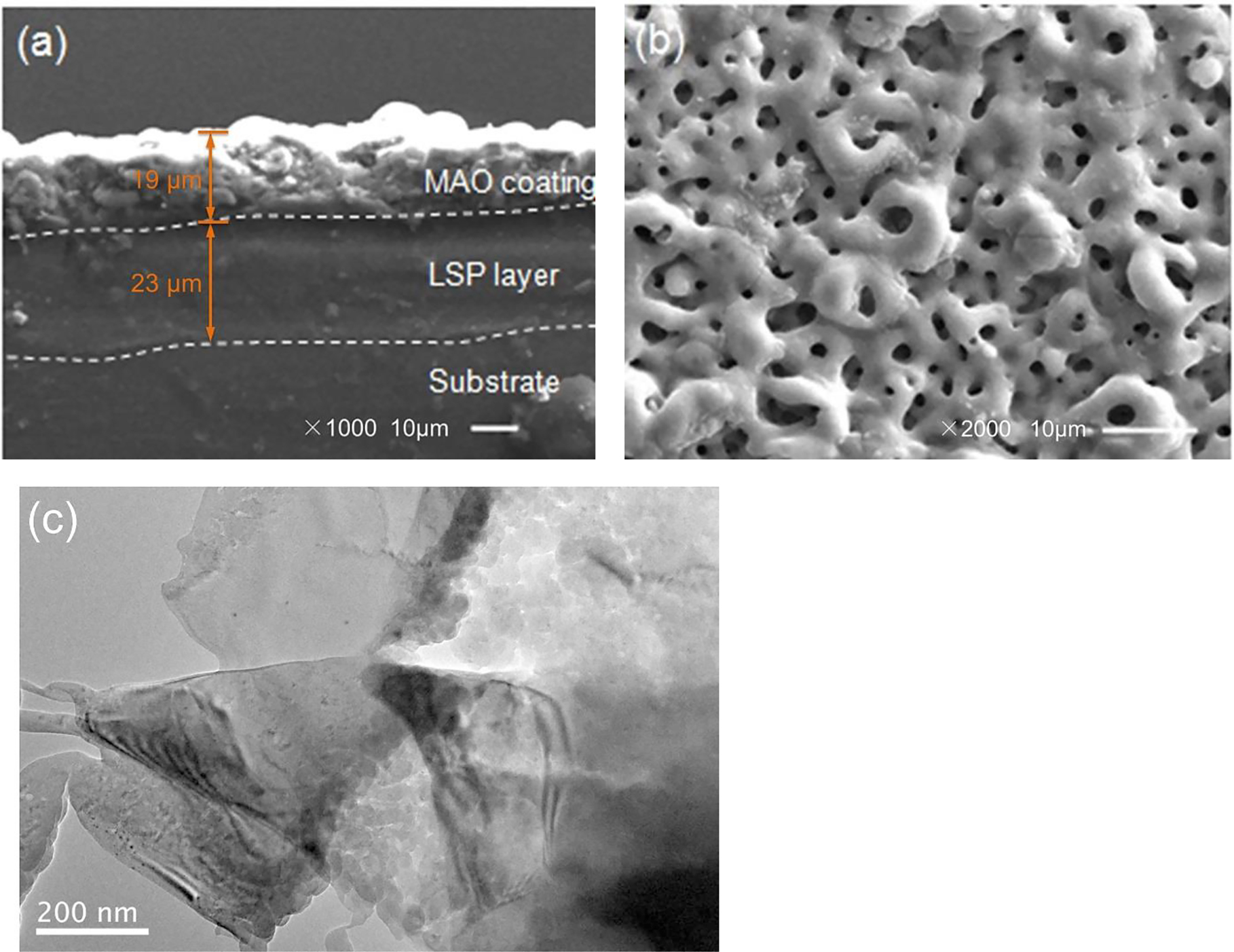
Microstructure of LSP/MAO coating: (a) SEM cross section; (b) SEM for MAO surface; (c) TEM for LSP area.
3.2 Wear volume
The 3D morphology and cross-sectional morphology of the wear tracks for the three specimens in SBF with three pH values are shown in Figures 2 and 3, respectively. The depth and width of the wear track are the key factor to evaluate the wear resistance (Kalin et al. 2003, 2006). It can be found that the depth and width of wear traces for the three specimens are the largest in pH 4 environment, indicating that the specimens have the worst corrosive-wear resistance under the acidic environment. On the other hand, the wear depth of LSP, MAO and LSP/MAO specimens are about 57, 68 and 51 μm, respectively. According to the thickness of coating in Figure 1a, it can be found that the coatings of the three specimens have been worn completely under the condition of pH 4. The wear traces of the three specimens in pH 7.4 environment are shallower and narrower compared with that in pH 4 environment, indicating that the corrosive-wear resistance of the coated specimens under the neutral conditions is better than that under the acidic conditions. In addition, the wear depth of LSP, MAO and LSP/MAO specimens are about 32, 35 and 27 μm, respectively, which indicates that the LSP and MAO coatings have been worn completely, while the LSP/MAO coating has not been worn through. The width and depth of the wear tracks for the three specimens in pH 9 environment are the smallest, indicating that the specimens have the best corrosive-wear resistance under the alkaline condition. The wear depth of LSP, MAO and LSP/MAO specimens under the condition are about 20, 26 and 18 μm, respectively, which indicates that the MAO coating has been worn completely, while the LSP and LSP/MAO coatings have not been worn completely. The width and depth of wear trace for MAO specimen are the largest, while that for LSP/MAO specimen are the smallest under the conditions of three pH values.
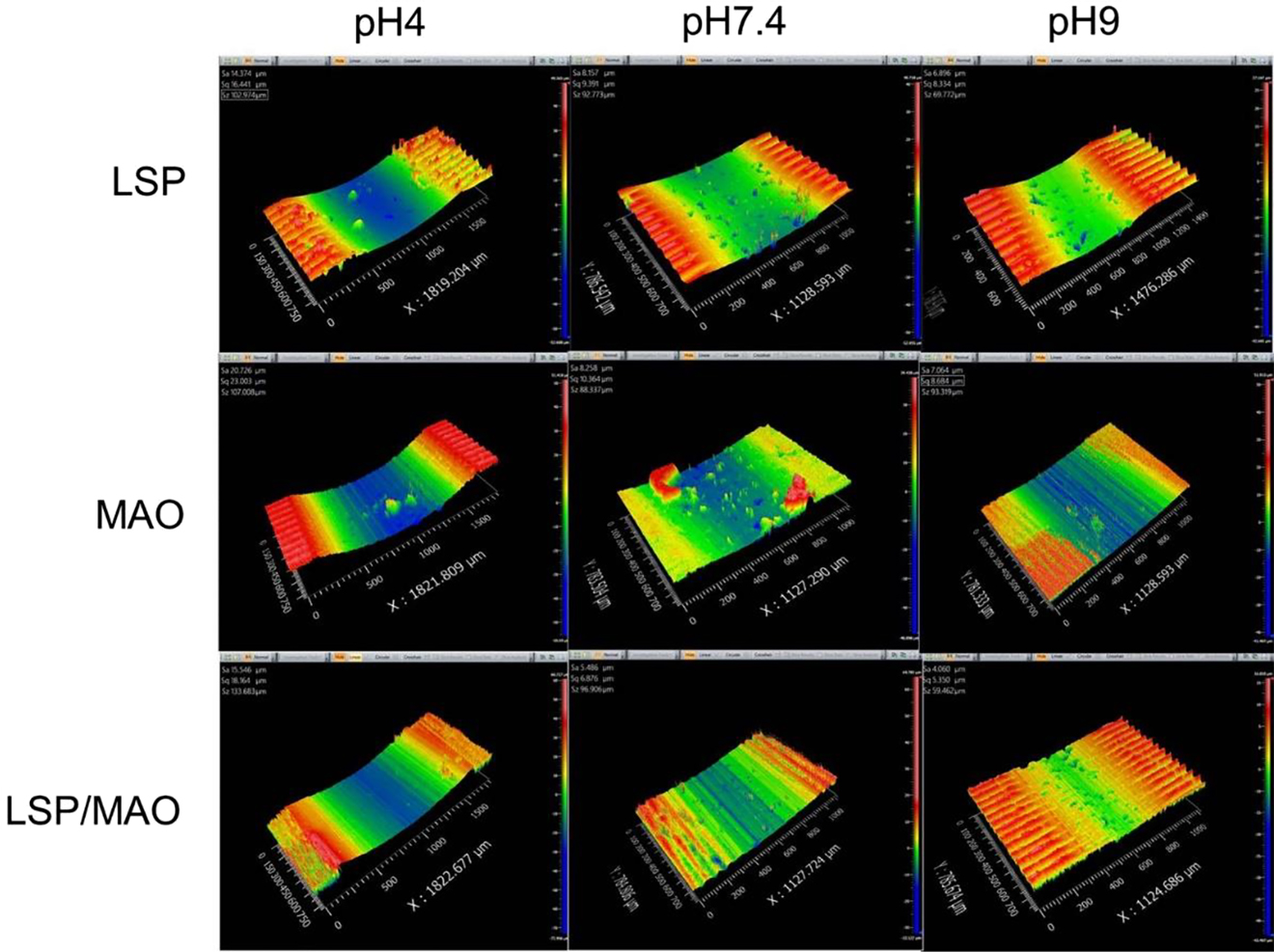
3D morphologies of three specimens in SBF with three pH values.
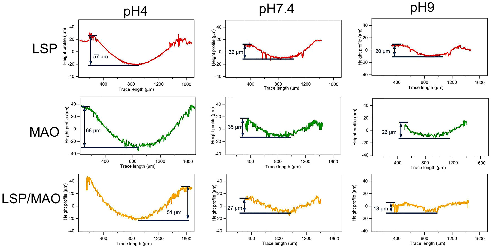
2D wear profiles of three specimens in SBF with three pH values.
The wear rate (Wr) of the specimens is calculated according to Eq. (1) in order to quantitatively compare the wear property of different specimens in the three pH environment, as shown in Figure 4. It can be seen that the wear rate of the MAO specimen (5.731) is the highest, followed by LSP specimen (5.126) and LSP/MAO specimen (4.123) in pH 4 environment. The trend of the wear rate for the specimens in pH 7.4 and pH 9 environments is the same as that in pH 4 environment, namely MAO > LSP > LSP/MAO. In addition, the wear rates of the three specimens decrease with the increase of pH values, namely pH 4 > pH 7.4 > pH 9. It is noteworthy that the wear rates of the specimens under acidic condition are much higher than that under neutral and alkaline conditions.
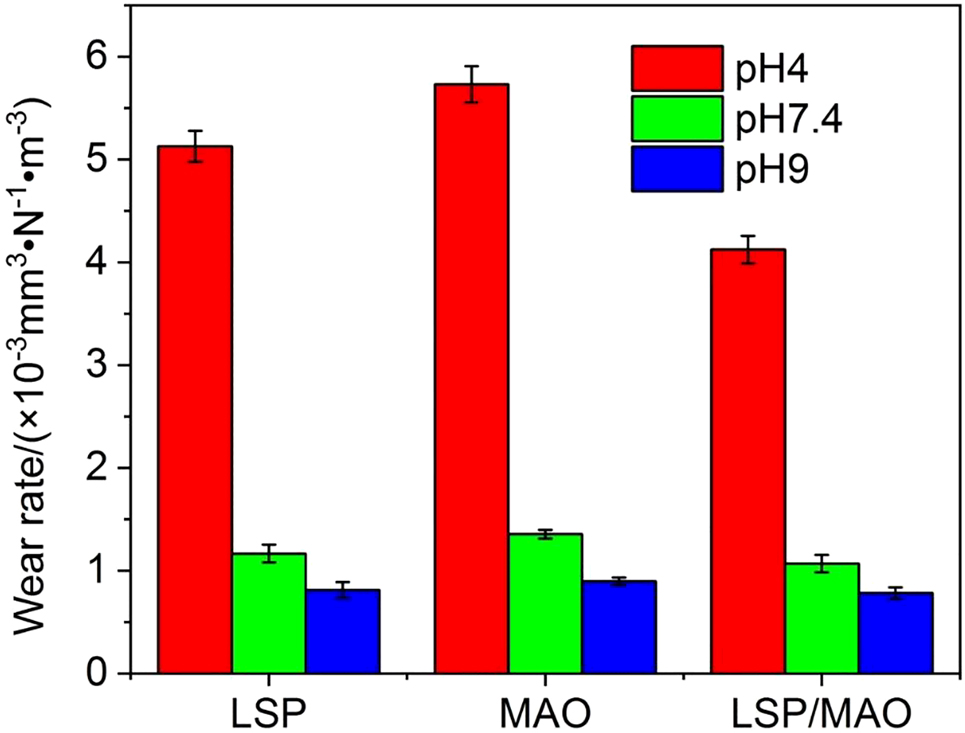
Wear rates of three specimens in SBF with three pH values.
3.3 Wear morphology and composition
The SEM images and EDS patterns of the worn surface for LSP, MAO and LSP/MAO specimens in the three pH environment are shown in Figures 5 and 6. In pH 4 environment, a lot of deep pits are presented on the worn surface of LSP specimen, and the worn surface produces more serious pitting simultaneously (Figure 5a). A lot of cracks and some wear debris (Figure 5d) are presented on the worn surface of MAO specimen. There are some micro-pits and micro-grooves parallel to the sliding direction (Figure 5g) on the worn surface of LSP/MAO specimen. In pH 7.4 environment, the worn surface of LSP specimen is covered with a film containing a small number of cracks and corrosion product particles (Figure 5b). The worn surface of MAO specimen presents deep grooves parallel to the sliding direction and a few deep pits (Figure 5e). There are only micro-grooves parallel to the sliding direction on the worn surface of LSP/MAO specimen. In pH 9 environment, the worn surface of LSP specimen is covered with a cracked adhesive layer (Figure 5c). A lot of grooves parallel to the sliding direction are observed on the worn surface of MAO specimen (Figure 5f). The worn surface of the LSP/MAO specimen is relatively intact, and almost no grooves are observed (Figure 5i). It can be seen from the worn morphologies of the three specimens in the three pH environments that the corrosive-wear resistance of LSP/MAO specimen is higher than that of LSP and MAO specimens.
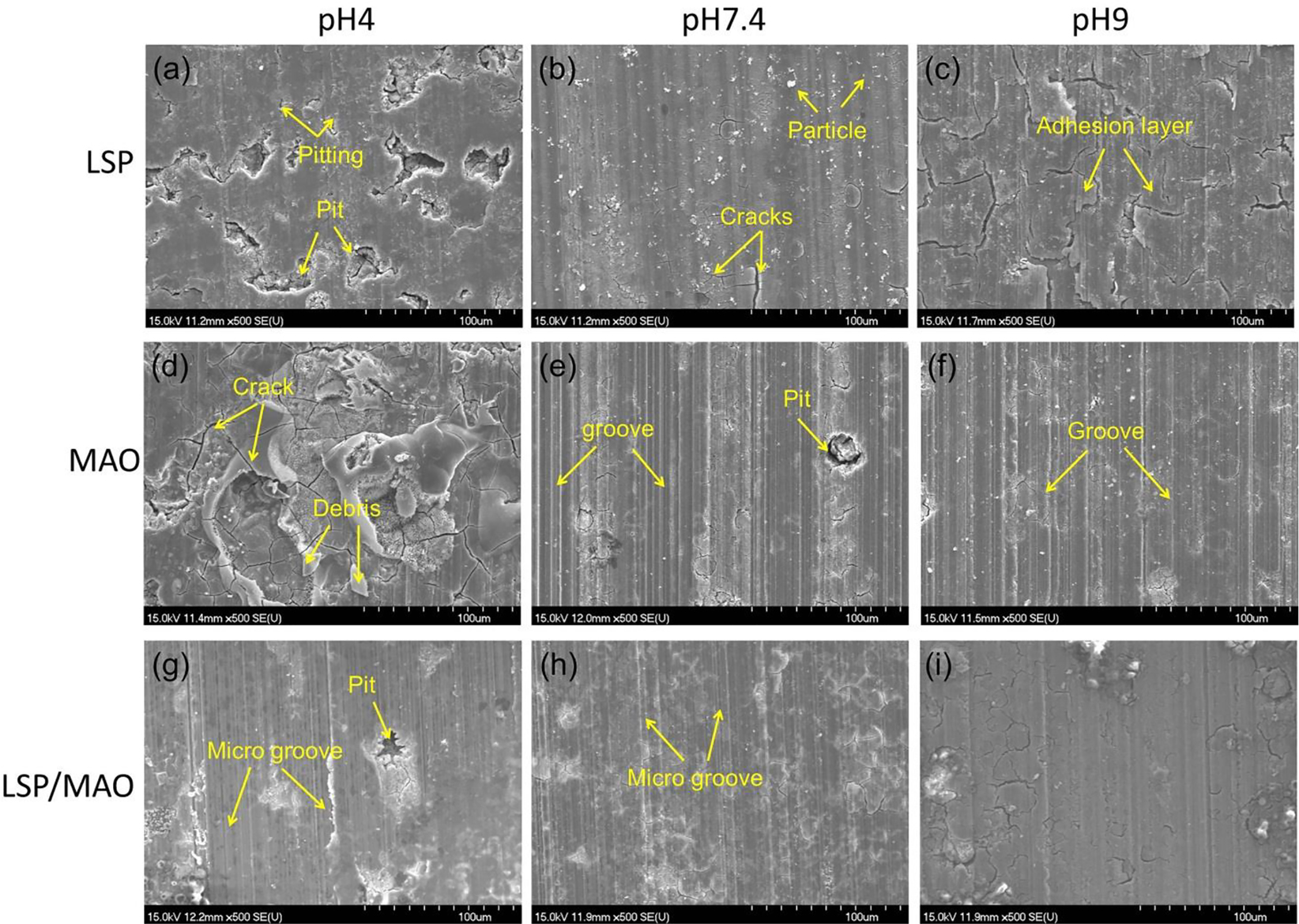
SEM morphologies of worn surface for three specimens in SBF with three pH values.
The EDS patterns of LSP specimen (Figure 6a–6c) show that there are C, Mg, O, P, Cl and Ca elements on the worn surface under the condition of three pH values. There are also characteristic elements such as F and Si in EDS patterns (Figure 6d–6i) for MAO and LSP/MAO specimens, which are derived from the electrolyte used for MAO coating preparation.
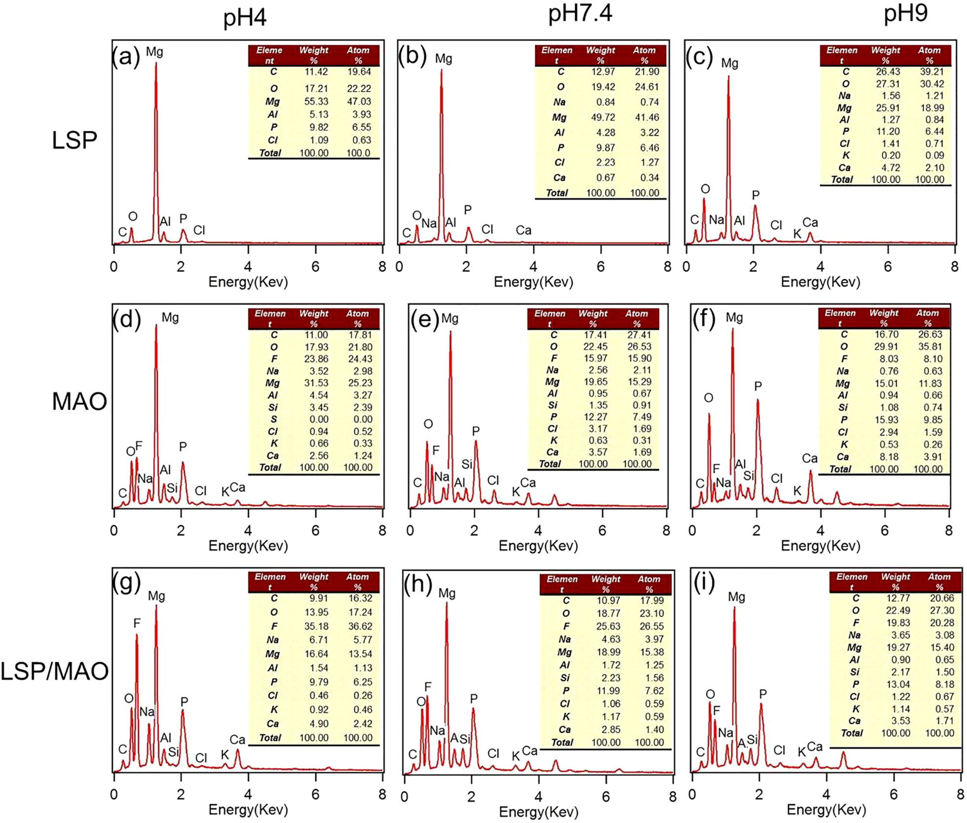
EDS patterns of worn surface for three specimens in SBF with three pH values.
4 Discussion
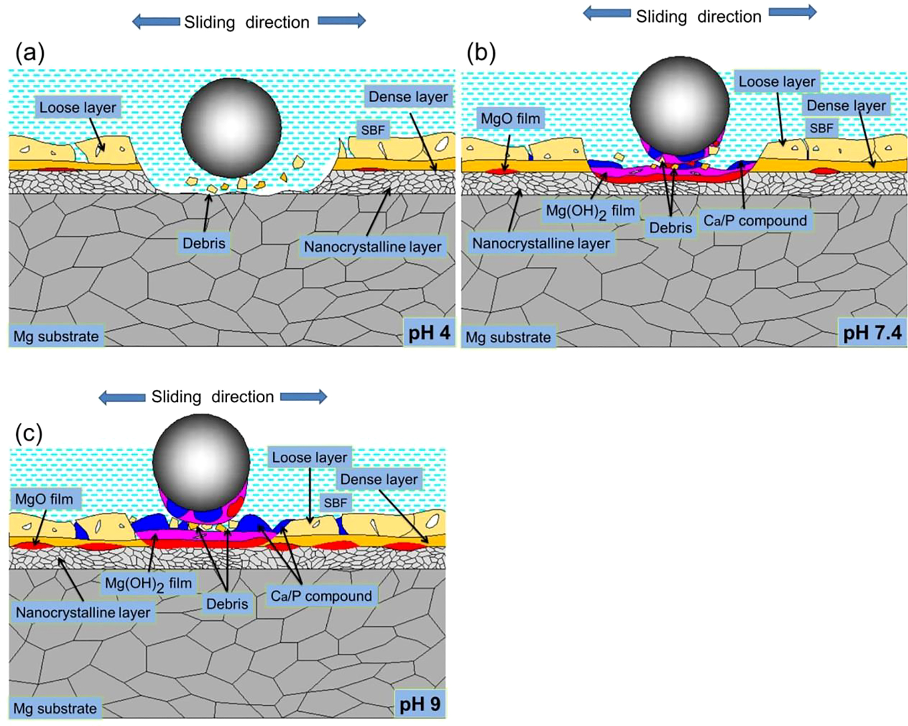
The wear models of LSP, MAO, and LSP/MAO specimens in the three pH environments are established based on the above test results (Section 3), as shown in Figures 7–9. The wear mechanisms of LSP specimens in the three pH environments are shown in Figure 7. In pH 4 environment (Figure 7a), the content of O, Ca and P on the worn surface is lower than that in pH 7.4 environment (Figure 6a and 6b). It is relate to that the neutralization of H+ and OH− inhibits the formation of Ca/P compounds (Eqs. (2) and (3)), and the Mg(OH)2 and MgO (Eqs. (11) and (12)) on the surface of specimens are dissolved by a large amount of H+ in SBF solution (Shen et al. 2020). In this case, there is almost no corrosion product layer on the worn surface, and the pitting is generated on the worn surface exposed to the SBF owing to the erosion of Cl− (Figure 5a). Then the cracks are produced in the pitting area under the action of repeated contact stress, and the cracks gradually grow and connect with each other, which leads to the material on the surface of the specimen falling off and a large number of deep pits are formed on worn surface (Figure 5a). This is a typical fatigue wear mechanism. Therefore, the reason for the large material loss and higher wear rate (Figure 4) of LSP specimen is the synergistic effect of corrosion wear and fatigue wear of LSP specimen in acid solution. In pH 7.4 environment (Figure 7b), the increase of OH− enables the corrosion product layer (MgO, Mg(OH)2 and Ca/P compound, etc.) to stably exist on the surface of specimen, thus corrosion of Cl ion on the surface of the specimen is prevented. As a result, the corrosion resistance of the worn surface increases. This is consistent with the result that the contents of O, Ca and P elements on the worn surface increase (Figure 6b). In this case, the corrosion product layer is gradually transferred to the 316L steel ball with the development of friction and wear, which leads to the formation of the adhesive wear mechanism. In addition, the frictional shear would be generated on the interface of corrosion product layer, which is attributed to the adhesion strength of the corrosion product layer is weaker than that of the friction pair. Thus, the direct wear on the surface of specimen is avoided. In other words, the corrosion wear of the specimen is inhibited by the corrosion product layer and the formation of adhesive wear. Therefore, the wear loss on the surface of specimen reduces. As a result, the wear rate of LSP specimen in pH 7.4 environment is much lower than that in pH 4 environment. In pH 9 environment (Figure 7c), the contents of O, Ca and P elements on the worn surface of LSP specimen further increase (Figure 6c). More corrosion product is generated on the worn surface of the specimen, which is attributed to the OH− content of the solution is increased due to the addition of NaOH when preparing the alkaline solution. As a result, the corrosion resistance of the specimen surface increases further. However, the thick corrosion product layer on the worn surface of the specimen is prone to crack under cyclic wear stress, and then a cracked adhesive layer is formed on the worn surface of specimen (Figure 5c). In this case, the adhesion strength of the corrosion product layer decreases, which leads to more corrosion product layer being transferred to 316L steel ball. As a result, the contact area of the friction pair increases further. Therefore, the friction stress acting on the surface of the specimen reduces, and the wear rate further decreases (Figure 4). In conclusion, the main wear mechanisms of LSP specimens in pH 7.4 and pH 9 environments are corrosion wear and adhesive wear.
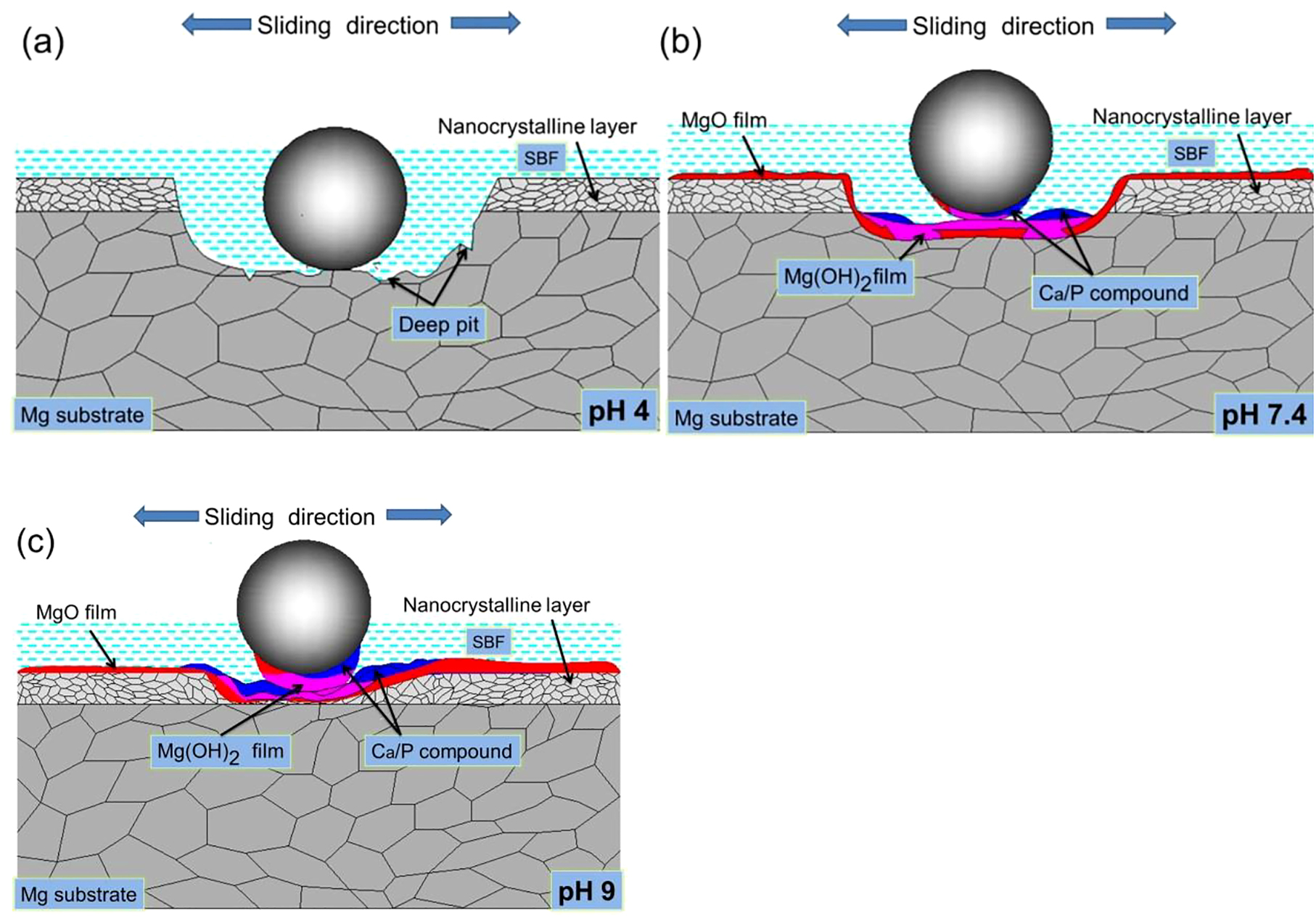
Wear diagrams of LSP specimen in SBF with three pH values.
The wear mechanisms of MAO specimen in the environments are shown in Figure 8. The MAO coating is a hard ceramic layer formed by micro arc oxidation, which is divided into two layers. The inner layer is relatively dense, while the outer layer is porous and has a few cracks. In pH 4 environment (Figure 8a), the EDS results (Figure 6d and 6e) show that the contents of O, Ca and P elements on the worn surface of the specimen are lower than that in pH 7.4 environment, indicating that the corrosion product formed on the surface of MAO specimen are very unstable. In this case, a large number of fragments are generated at the initial stage of wear due to the brittle, hard and porous characteristics of the MAO coating, which leads to plough-type abrasive wear on the surface of the specimen and even partially exposes the substrate material. As a result, there is serious wear loss on the worn surface. On the other hand, a large-scale localized corrosion (Figure 5d) is formed on the worn surface of MAO specimens. It is attribute to the solution rich in Cl− is more likely to penetrate the porous outer layer to erode the inner layer, or directly erode the exposed substrate. The material on the worn surface of the specimen is loosened by localized corrosion, and then a large number of cracks (Figure 5d) are generated on the corroded worn surface under the action of abrasion cyclic stress. It is also a typical fatigue wear mechanism. At this point, there is a lot of material loss on the worn surface of the specimen under the synergistic effect of wear mechanisms contain abrasive wear, corrosion wear and fatigue wear. Therefore, the wear rate of MAO specimen in pH 4 environment is higher than that of LSP specimen (Figure 4). In pH 7.4 environment (Figure 8b), the contents of O, Ca and P elements observed on the worn surface increase (Figure 6e) compared with that in pH 4 environment (Figure 6d), indicating that a stable corrosion product layer has formed on the worn surface of MAO specimen. At the same time, the adhesive wear is formed by the corrosion product layer and 316L steel ball. Furthermore, the corrosion product layer not only improves the plough-type abrasive wear caused by the defects of the MAO coating, but also further reduces the wear loss of the specimen surface. As a result, the wear rate of MAO specimen in pH 7.4 environment is lower than that in pH 4 environment. In pH 9 environment (Figure 8c), The EDS result of the worn surface shows that the contents of O, Ca and P elements are higher than those in pH 7.4 environment (Figure 6e and 6f), which indicates that a thicker corrosion product layer is formed on the surface of MAO specimen. As a result, the corrosion resistance of the specimens further improves and the plough-type abrasive wear effect further decreases. Therefore, the wear rate of MAO specimen in pH 9 environment further decreases (Figure 4) compared with that in pH 7.4. The contents of O, Ca and P elements on the worn surface of MAO specimen (Figure 6e and 6f) are much higher than those of LSP specimen (Figure 6b and 6c) under neutral and alkaline conditions, indicating that the thickness of the corrosion product layer formed on the worn surface of MAO specimen is thicker than that of LSP specimen. Although the corrosion product layer is beneficial to improve the corrosion resistance of the specimen, the MAO coating is severely damaged by plough-type abrasive wear. As a result, the localized corrosion of MAO specimen becomes more serious. The features of a few deep pits and grooves on the worn surface of MAO specimen (Figure 5e and 5f) also prove that the corrosion product layer has been damaged. Therefore, the corrosion wear rate of MAO specimen in pH 7.4 and 9 environments is higher than that of LSP specimen due to the combined effect of abrasive wear, adhesive wear and corrosive wear (Figure 4).
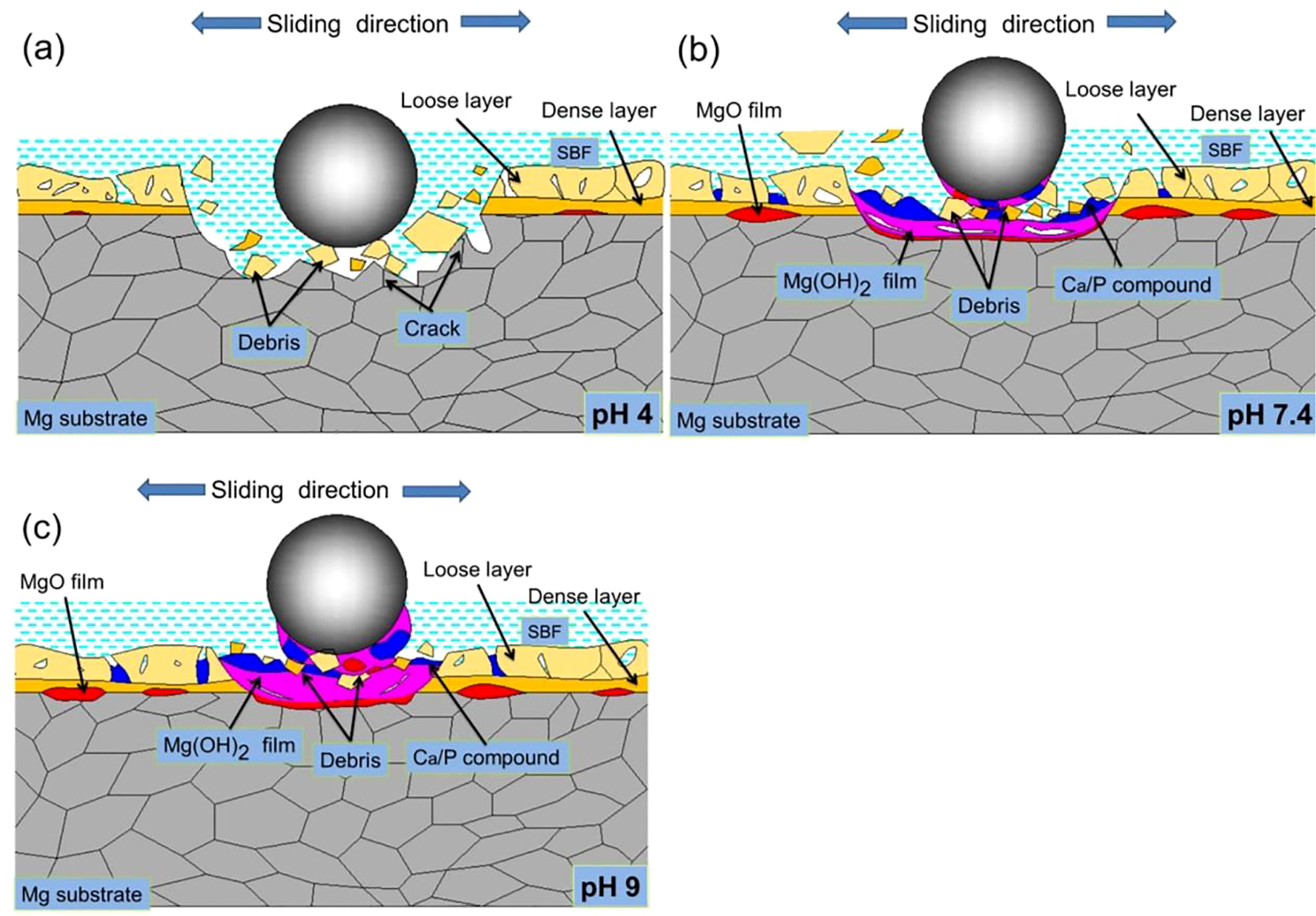
Wear diagrams of MAO specimen in SBF with three pH values.
The wear mechanisms of LSP/MAO specimen in the three pH environments are shown in Figure 9. The LSP/MAO composite coating is divided into two layers. The outer layer is porous, and the inner layer is composed of LSP nano-crystalline layer and MAO dense layer. Previous studies have proved that the bonding strength between the substrate and MAO coating is improved by the fine-grained LSP layer, and the surface of the LSP/MAO composite coating has a lower porosity (Xiong et al. 2017). It can be inferred that the volume fraction of fragments generated by the LSP/MAO composite coating is lower than that of the MAO coating at the initial wear stage. Therefore, the influence of the fragments on plough-type abrasive wear of materials weakens, and the material loss of specimen reduces. In pH 4 environment (Figure 9a), The EDS results show that the contents of O, Ca, P elements decrease compared with pH 7.4 (Figure 6g and 6h). Although the LSP/MAO composite coating is not protected by the corrosion product layer, the corrosion resistance of LSP/MAO specimen is better than that of MAO specimen. This is because the surface porosity of the LSP/MAO composite coating decreases, and the thickness of the coating increases compared with MAO coating (Shen et al. 2020). As a result, the wear rate of LSP/MAO specimen in pH 4 environment is lower than that of MAO and LSP specimens (Figure 4). In pH 7.4 (Figure 9b) and pH 9 (Figure 9c) environment, the wear mechanism of the LSP/MAO composite coating is similar to that of the MAO coating. Nevertheless, the adsorption of LSP/MAO specimen is weaker than that of MAO specimen due to the low porosity of the LSP/MAO composite coating. Consequently the amount of corrosion products deposited on the worn surface of LSP/MAO specimen is less, which is consistent with the result that the contents of O, Ca and P elements on the worn surface of LSP/MAO specimen are lower than those of MAO specimen (Figure 6b, 6c, 6e, and 6f). However, the protective effect of the corrosion product layer on the surface of LSP/MAO specimen is better than that of MAO specimen due to the weakening of plough-type abrasive wear. This is also confirmed by the fact that only slight grooves appear on the worn surface of the LSP/MAO composite coating (Figure 5h and 5i) compared with a single MAO coating. On the other hand, the LSP nano-crystalline layer with fine grain contributes to the formation of MgO film in SBF environment (Xiong et al. 2019) which further improves the corrosive-wear resistance of LSP/MAO specimen. Therefore, the wear rate of LSP/MAO specimen in pH 7.4 and pH 9 environments is lower than that of the MAO specimen in pH 7.4 and pH 9 environments (Figure 4). In conclusion, the corrosive-wear resistance of magnesium alloys can be more effectively improved by the LSP/MAO composite coating.
Wear diagrams of LSP/MAO specimen in SBF with three pH values.
The micro-action between the implant and the implant, the implant and the bone tissue is likely to cause friction and wear during the service of magnesium alloy implants in human body fluids. At the same time, the pH of body fluid also changes significantly during the healing process of bone tissue. The pH value of human body fluids is 7.4 under normal circumstances, but the pH value of body fluids will decrease due to the inflammatory reaction at the implantation site after the implantation of alloy implants. In addition, the local pH of body fluids will increase significantly during the healing process of bone tissue. However, the friction-wear behavior of treated magnesium alloy in SBF solutions with different pH has not been reported. Therefore, it is particularly important to study the corrosive-wear properties of treated magnesium alloys under different pH conditions. The corrosive-wear characteristics of treated magnesium alloys in SBF solutions with three pH values were studied in this paper, which can provide reference for the changing principle and mechanism of corrosive-wear of magnesium alloy implanted devices in different human environments.
5 Conclusions
The wear test of surface-treated AZ80 magnesium alloy (LSP, MAO, LSP/MAO specimens) was carried out in SBF with three pH values (pH 4, pH 7.4 and pH 9). The main conclusions were drawn:
The wear rates of LSP, MAO and LSP/MAO specimens at three pH environment followed: pH 4 > pH 7.4 > pH 9, and the wear rates of the three specimens in the same pH solution followed: MAO > LSP > LSP/MAO.
For LSP specimen, the main wear mechanisms were fatigue wear and corrosion wear in SBF with pH 4 value, and adhesive wear and corrosion wear in SBF with pH 7.4 and pH 9 values.
For MAO specimen, the wear mechanisms included abrasive wear, fatigue wear and corrosion wear in pH 4 environment, and abrasive wear, adhesive wear and corrosion wear in pH 7.4 and pH 9 environments.
The corrosive-wear resistance of LSP/MAO specimen was effectively improved, which was attribute to that the abrasive wear and corrosive wear of the LSP/MAO specimens in three pH environments were improved due to the interaction of the LSP fine-grained layer and the MAO coating.
Funding source: National Natural Science Foundation of China
Award Identifier / Grant number: 52175151
Award Identifier / Grant number: 51775502
Funding source: Natural Science Foundation of Zhejiang Province
Award Identifier / Grant number: LY20E050024
-
Author contribution: All the authors have accepted responsibility for the entire content of this submitted manuscript and approved submission.
-
Research funding: The authors gratefully acknowledge the project sponsored by the support from National Natural Science Foundation of China (nos. 52175151, 51775502) and the Natural Science Foundation of Zhejiang Province (no. LY20E050024).
-
Conflicts of interest: The authors declare no conflicts of interest regarding this article.
References
Bakhsheshi-Rad, H.R., Hamzah, E., Daroonparvar, M., AbdulKadir, M.R., Kasiri-Asgarani, M., and Staiger, M.P. (2016). Enhancement of corrosion resistance and mechanical properties of Mg-1.2Ca-2Bi via a hybrid silicon-biopolymer coating system. Surf. Coating. Technol. 301: 133–139, https://doi.org/10.1016/j.surfcoat.2015.09.039.Suche in Google Scholar
Chen, H. and Alpas, A.T. (2000). Sliding wear map for the magnesium alloy Mg-9Al-0.9 Zn (AZ91). Wear 246: 106–116, https://doi.org/10.1016/s0043-1648(00)00495-6.Suche in Google Scholar
Dai, J.W., Zhang, X.B., Yin, Q., Ni, S.N., Ba, Z.X., and Wang, Z.Z. (2017). Friction and wear behaviors of biodegradable Mg-6Gd-0.5Zn-0.4Zr alloy under simulated body fluid condition. J. Magnes. Alloys 5: 448–453, https://doi.org/10.1016/j.jma.2017.11.002.Suche in Google Scholar
Froes, F., Eliezer, D., and Aghion, E. (1998). The science, technology, and applications of magnesium. JOM 50: 30–34, https://doi.org/10.1007/s11837-998-0411-6.Suche in Google Scholar
Gnedenkov, A.S., Sinebryukhov, S.L., Mashtalyar, D.V., and Gnedenkov, S.V. (2016). Protective properties of inhibitor-containing composite coatings on a Mg alloy. Corrosion Sci. 102: 348–354, https://doi.org/10.1016/j.corsci.2015.10.026.Suche in Google Scholar
Gu, Y.H., Zheng, X.H., Liu, Q., Ma, H.J., Zhang, L., and Yang, D.W. (2018). Investigating corrosion performance and corrosive wear behavior of sol–gel/MAO-coated Mg alloy. Tribol. Lett. 66: 101, https://doi.org/10.1007/s11249-018-1052-8.Suche in Google Scholar
Hornberger, H., Virtanen, S., and Boccaccini, A.R. (2012). Biomedical coatings on magnesium alloys—a review. Acta Biomater. 8: 2442–2455, https://doi.org/10.1016/j.actbio.2012.04.012.Suche in Google Scholar PubMed
Kalin, M., Drai, G., Novak, S., and Vizintin, J. (2006). Wear mechanisms associated with the lubrication of zirconia ceramics in various aqueous solutions. J. Eur. Ceram. Soc. 26: 223–232, https://doi.org/10.1016/j.jeurceramsoc.2004.10.026.Suche in Google Scholar
Kalin, M., Novak, S., and Vizintin, J. (2003). Wear and friction behavior of alumina ceramics in aqueous solutions with different pH. Wear 254: 1141–1146, https://doi.org/10.1016/s0043-1648(03)00326-0.Suche in Google Scholar
Kaunitz, J.D. and Yamaguchi, D.T. (2008). TNAP, TrAP, ecto-purinergic signaling, and bone remodeling. J. Cell. Biochem. 105: 655–662, https://doi.org/10.1002/jcb.21885.Suche in Google Scholar PubMed
Li, H., Liu, D.B., Zhao, Y., Jin, F., and Chen, M.F. (2016). The influence of Zn content on the corrosion and wear performance of Mg-Zn-Ca alloy in simulated body fluid. J. Mater. Eng. Perform. 25: 3890–3895, https://doi.org/10.1007/s11665-016-2207-0.Suche in Google Scholar
Li, Q.Y., Zhang, Q.Q., and An, M.Z. (2018). Enhanced corrosion and wear resistance of AZ31 magnesium alloy in simulated body fluid via electrode-position of nano-crystalline zinc. Materialia 4:282–286, https://doi.org/10.1016/j.mtla.2018.09.038.Suche in Google Scholar
Liu, C., Liang, J., Zhou, J., Wang, L., and Li, Q. (2015). Effect of laser surface melting on microstructure and corrosion characteristics of AM60B magnesium alloy. Appl. Surf. Sci. 343: 133–140, https://doi.org/10.1016/j.apsusc.2015.03.067.Suche in Google Scholar
Liu, D.B., Wu, B., Wang, X., and Chen, M.F. (2015). Corrosion and wear behavior of an Mg–2Zn–0.2Mn alloy in simulated body fluid. Rare Met. 34: 553–559, https://doi.org/10.1007/s12598-013-0052-y.Suche in Google Scholar
Liu, L.H., Yang, C., Wang, F., Qu, S.G., Li, X.Q., Zhang, W.W., Li, Y.Y., and Zhang, L.C. (2015). Ultrafine grained Ti-based composites with ultrahigh strength and ductility achieved by equiaxing microstructure. Mater. Des. 79: 1–5, https://doi.org/10.1016/j.matdes.2015.04.032.Suche in Google Scholar
Liu, S., Dai, J., Ni, S., Wang, Z., and Zhang, X. (2017). Synergistic effects of wear and corrosion on mass loss of GZ62K alloy in simulated body fluid for orthopedic application. Surf. Rev. Lett. 25: 1950021.10.1016/j.matdes.2015.04.032Suche in Google Scholar
Lopez, M.A., Pereda, M.D., Valle, J.A., Lorenzo, M.F., Garcia-Alonso, M.C., Ruano, O.A., and Escudero, M.L. (2010). Corrosion behavior of AZ31 magnesium alloy with different grain sizes in simulated bio-logical fluids. Acta Biomater. 6: 1763, https://doi.org/10.1016/j.actbio.2009.04.041.Suche in Google Scholar PubMed
Meng, Y., Gao, H., Hu, J., and Gao, L. (2019). Effect of pH value on the corrosion and corrosion fatigue behavior of AM60 magnesium alloy. J. Mater. Res. 34: 1054–1063, https://doi.org/10.1557/jmr.2018.489.Suche in Google Scholar
Nouri, M. and Li, D.Y. (2017). Maximizing the benefit of aluminizing to AZ31 alloy by surface nano-crystallization for elevated resistance to wear and corrosive wear. Tribol. Int. 111: 211–219, https://doi.org/10.1016/j.triboint.2017.03.009.Suche in Google Scholar
Saffarzade, P., Amadeh, A.A., and Agahi, N. (2020). Study of tribological and friction behavior of magnesium phosphate coating and comparison with traditional zinc phosphate coating under dry and lubricated conditions. Tribol. Int. 144: 106122, https://doi.org/10.1016/j.triboint.2019.106122.Suche in Google Scholar
Shen, Y.S., He, L.Y., Yang, Z.Y., and Xiong, Y. (2020). Corrosion behavior of different coatings prepared on the surface of AZ80 magnesium alloy in simulated body fluid. J. Mater. Eng. Perform. 29: 1609–1621, https://doi.org/10.1007/s11665-020-04682-4.Suche in Google Scholar
Staiger, M.P., Pietak, A.M., Huadmai, J., and Dias, G. (2006). Magnesium and its alloys as orthopedic biomaterials: a review. Biomaterials 27: 1728–1734, https://doi.org/10.1016/j.biomaterials.2005.10.003.Suche in Google Scholar PubMed
Wang, C., Zhang, D., and Jiang, Y. (2006). Growth process and wear resistance for ceramic coatings formed on Al–Cu–Mg alloy by micro-arc oxidation. Appl. Surf. Sci. 253: 674–678, https://doi.org/10.1016/j.apsusc.2005.12.156.Suche in Google Scholar
Witte, F. (2010). The history of biodegradable magnesium implants: a review. Acta Biomater. 6: 1680–1692, https://doi.org/10.1016/j.actbio.2010.02.028.Suche in Google Scholar PubMed
Wood, K.R.J. (2010). Tribology of thermal sprayed WC–Co coatings. Int. J. Refract. Metals Hard Mater. 28: 82–94, https://doi.org/10.1016/j.ijrmhm.2009.07.011.Suche in Google Scholar
Xiong, W.J., Ma, M.Y., Zhang, J., and Lian, Y. (2020). The effects of Cr2O3 particles on the microstructure and wear-resistant properties of electrodeposited CoNiP coatings. Surf. Coating. Technol. 381: 125167, https://doi.org/10.1016/j.surfcoat.2019.125167.Suche in Google Scholar
Xiong, Y., Hu, Q., Song, R.G., and Hu, X.X. (2017). LSP/MAO composite bio-coating on AZ80 magnesium alloy for biomedical application. Mater. Sci. Eng. C 75: 1299–1304, https://doi.org/10.1016/j.msec.2017.03.003.Suche in Google Scholar PubMed
Xiong, Y., Lu, C., Wang, C., and Song, R.G. (2015). Degradation behavior of n-MAO/EPD bio-ceramic composite coatings on magnesium alloy in simulated body fluid. J. Alloys Compd. 625: 258–265, https://doi.org/10.1016/j.jallcom.2014.11.084.Suche in Google Scholar
Xiong, Y., Yang, Z.Y., Song, R.G., and Hu, X.X. (2019). Degradation behavior of AZ80 magnesium alloy with LSP/MAO composite bio-coating in simulated body fluid. Mater. Res. Express 6: 116587, https://doi.org/10.1088/2053-1591/ab4aae.Suche in Google Scholar
Xu, L., Yu, G., Zhang, E., Pan, F., and Yang, K. (2010). In vivo corrosion behavior of Mg-Mn-Zn alloy for bone implant application. J. Biomed. Mater. Res. 83: 703–711, https://doi.org/10.1002/jbm.a.31273.Suche in Google Scholar PubMed
Xiong, Y., Shen, Y.S., He, L.Y., Yang, Z.Y., and Song, R.G. (2020). Stress corrosion cracking behavior of LSP/MAO treated magnesium alloy during SSRT in a simulated body fluid. J. Alloys Compd. 822: 153707, https://doi.org/10.1016/j.jallcom.2020.153707.Suche in Google Scholar
Yun, H.Y., Dong, Z., Yang, D., Schulz, M.S., Shanov, V.N., Yarmolenko, S., Xu, Z., Kumta, P., and Sfeir, C. (2009). Biodegradable Mg corrosion and osteoblast cell culture studies. Mater. Sci. Eng. C 29: 1814–1821, https://doi.org/10.1016/j.msec.2009.02.008.Suche in Google Scholar
Zhang, X., Dai, J., Zhang, J., and Bai, Y. (2018). Quantitative Evaluation of the interaction between wear and corrosion on Mg-3Gd-1Zn Alloy in simulated body fluid. J. Mater. Eng. Perform. 28: 355–362, https://doi.org/10.1007/s11665-018-3770-3.Suche in Google Scholar
© 2021 Walter de Gruyter GmbH, Berlin/Boston
Artikel in diesem Heft
- Frontmatter
- Review
- A review on the corrosion resistance of electroless Ni-P based composite coatings and electrochemical corrosion testing methods
- Original Articles
- Water-droplet erosion behavior of high-velocity oxygen-fuel-sprayed coatings for steam turbine blades
- Corrosion characteristics of plasma spray, arc spray, high velocity oxygen fuel, and diamond jet coated 30MnB5 boron alloyed steel in 3.5 wt.% NaCl solution
- Corrosive-wear behavior of LSP/MAO treated magnesium alloys in physiological environment with three pH values
- Effect of carbon nanotubes on microstructure and corrosion resistance of PEO ceramic coating of magnesium alloy
- Investigating the efficacy of Curcuma longa against Desulfovibrio desulfuricans influenced corrosion in low-carbon steel
- Annual Reviewer Acknowledgement
- Reviewer acknowledgement Corrosion Reviews volume 39 (2021)