Biomechanical effect of different femoral neck blade position on the fixation of intertrochanteric fracture: a finite element analysis
-
Pei-Yuan Lee


Abstract
Medial migration or cutout of the neck helical blade has commonly occurred in the treatment of trochanteric fracture of the femur. The position of the helical blade within the femoral head is one of the influencing factors that cause the blade to perforate the intact joint surface; however, the ideal placement of the helical blade is not currently known. A finite element model of a femur/nail construct was utilized to analyze five possible blade positions in the femoral head. Normal strain at the fracture surface, the minimum principal strain in the cancellous bone, and the von Mises stress in the implant itself were calculated and compared between different blade positions. The results showed that a large area of normal compressive strain at the fracture surface was observed in the inferior and posterior blade positions. The volume of cancellous bone strained to yielding in the femoral head and neck was lower for the inferior and posterior positions, whereas it was the highest for the superior position. The inferior and posterior positions had lower von Mises stress in the implant itself. The inferior and posterior positions may be the ideal position for the intramedullary nail with a helical neck blade.
Introduction
Cephalomedullary nails are the primary surgical treatment for unstable pertrochanteric fracture, although there are some limitations to these implant designs. The Gamma nail was the first widely available intramedullary implant used for the fixation of trochanteric fractures. This device consists of a sliding lag screw that is fixed in the femoral head and two distal locking screws that pass through the nail tip to secure it to the femoral shaft. While good clinical outcomes had been reported [3], postoperative complications such as femoral shaft fracture [4], implant breakage [25], and cutout of the lag screw have emerged, which represent device-related adverse effects. The cutout rates reported can be as high as 8% [9, 32].
In 2004, a helical blade design (proximal femoral nail antirotation, PFNA) was introduced to overcome the known limitations and potential sources of complications of the Gamma device [33]. However, complications were also revealed, such as mismatch between the proximal end of the nail and greater trochanter [30]; a mismatch between the short nail and the anterior bowing of the femoral canal [19]; and medial migration or cut through of the helical blade [5, 8, 36]. Recently, a new cephalomedullary nail, the Asia Anatomic Anteversion Hip Nail (A Plus Biotechnology Co., Ltd., New Taipei City, Taiwan) with a helical neck blade was developed upon the femoral morphology of the Chinese population [23], which is anticipated to obviate the above-mentioned complications of the PFNA, especially the Asian version, PFNA-II.
The position of the lag screw or the helical blade within the femoral head is one of the influencing factors that cause the screw or blade to perforate the intact joint surface. Tip-apex distance (TAD) is a widely accepted index to quantify the screw position so as to evaluate the cutout risk of the lag screw. Generally, it is concluded that TAD >25 mm is a strong predictor of cutout. Many previously published biomechanical/computational studies focused on the biomechanical effect of different positions of the lag screw for fixing of peritrochanteric fracture [10, 11, 21, 35], but controversy exists among authors. As for blade design, little is known about the ideal position of the neck blade in the treatment of trochanteric fractures. A biomechanically or clinically superior position of the helical blade within the femoral head is still not well investigated. The aim of this study was to investigate the biomechanical behavior of the trochanteric femoral fracture stabilized by the helical blade in five possible positions in the femoral head, by means of finite element (FE) analysis.
Materials and methods
Three-dimensional modeling of the femur
A healthy femur of a female (60-year-old) with nonpathologic and normal low limb alignment bones accepted computed tomography (CT) scan at Show Chwan Memorial Hospital. The CT scan (Light Speed VCT, GE Medical System, General Electric Company, Fairfield, CT, USA) (protocol: voltage 120 kV, pitch 0.984, standard reconstruction kernel) was collected with slice thickness of 1.25 mm and 512×512 pixels per image, which was approved by the Institutional Review Board of Show Chwan Memorial Hospital (No. 1010705). A complete femur segmentation from proximal to distal ends was acquired, and each image was obtained in Digital Imaging and Communications in Medicine format. The CT scan data were then imported into a self-development imaging software to outline inner and outer contours of the cortical bone. The boundaries of cortical shell and cancellous core were defined from the grayscale difference of the CT image. Cortical bone and cancellous bone were modeled as two separate sections. A CAD software, PTC Creo 2.0 (Parametric Technologies Corp., Needham, MA, USA) was utilized to reconstruct the three-dimensional (3D) femur model via the cortical and cancellous contours.
The cephalomedullary nail and fracture models
The CAD model of a cephalomedullary nail, Asia Anatomic Anteversion Hip Nail (A Plus Biotechnology Co., Ltd., New Taipei City, Taiwan) was obtained from the manufacturer, which is characterized by a helical blade, hammer-in, and large circumference contact area (Figure 1A). The dimensions of the Asia Anatomic Anteversion Hip Nail were obtained from the manufacturer, and the 3D model was constructed via PTC Creo. Following reconstruction of the computer nail model, the implant was “virtually” inserted into the femur model. The implant was manipulated by translation and rotation so that five positions in the femoral head (anterior, posterior, superior, inferior, and central) were achieved (Figure 1B). Thereafter, simulation of intertrochanteric fracture was performed according to AO (Arbeitsgemeinschaft für Osteosynthesefragen) classification 31-A2 [26]. The intertrochanteric fracture was “virtually cut” by a plane in the CAD software. The angle of the fracture line with the femoral shaft (anatomical axis) was designated as 45° according to Goffin et al.’s studies [10, 11]. These models were then imported into an FE solver (ANSYS, ANSYS Inc., Canonsburg, PA, USA). Convergence tests were performed on the FE model to qualify the model meshing. To evaluate the accuracy of our FE models, a convergence test of total strain energy was performed. For the convergence test, a new FE model with more element numbers was calculated, and the results of the presented FE model was compared with that of the new FE model. The mesh generated for each models contained 573,685 elements on average. Due to the complex geometry of the blade and nail, the mesh consists of tetrahedral elements only.
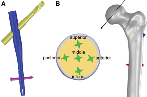
(A) The CAD model of the cephalomedullary nail utilized for evaluation of the cutout risk of five different blade positions. (B) Diagram showing a cross section of the femoral head illustrating the five different positions of the helical blades.
Boundary and loading conditions
As for FE analysis, both the bone and the implant were assumed to be isotropic and linearly elastic materials. Elastic modulus and Poisson’s ratio are respectively assigned to the values of 17.5 GPa and 0.3 for the cortical bone and 1.5 GPa and 0.12 for the trabecular bone [16]. The cephalomedullary implant was considered to be made of titanium alloy (Ti6Al4V) with an elastic modulus of 110 GPa and a Poisson’s ratio of 0.3. For loading and boundary conditions, static loads applied to the FE models, which were based on the study by Heller et al. [13, 14] for stair climbing, consist of the hip contact load and a set of simplified muscle forces (abductor, vastus lateralis, and vastus medialis), and the distal end of the femur was fully fixed (Figure 2). For the interfacial surfaces between the different parts of the models, frictional contacts were defined, whereby elevation and relative tangential displacement are possible in bone-bone interactions, bone-implant interactions, and implant-implant interactions. Friction coefficient is 0.46 for bone-bone interactions [7], 0.42 for bone-implant interactions [17], and 0.2 for implant-implant interactions [34].
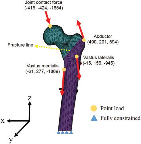
The finite-element models used in this study with AO 31-A2 fracture and the loading and boundary conditions, including the applied load and muscle forces.
To understand the extent of “surgical error tolerance” of the blade positioning within the femoral head and the effect of the blade positioning on bony healing (i.e. osteosynthesis), the TAD, normal strain distribution in the fracture surface, minimum principal strains in cancellous bone in the femoral head and neck, and von Mises stress values at the implant were compared between different blade positions.
Results
Normal strain distribution maps in the fracture surface are shown in Figure 3 for the five helical blade positions. Higher maximum compressive strain was found in the inferior position (Table 1). The compressive strain distribution is similar for the middle, anterior, and posterior cephalic blades, while it reduces for the superior case.
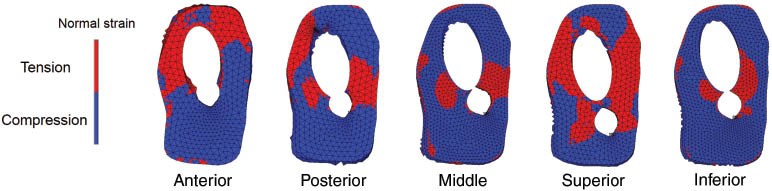
Diagram showing the normal strain distribution in fracture surface for five different blade positions.
The maximum (tensional) and minimum (compressive) normal strains on the fracture surface for five blade positions.
| Blade position | Anterior | Posterior | Middle | Superior | Inferior |
|---|---|---|---|---|---|
| Maximun strain (%) | 0.072 | 0.067 | 0.044 | 0.083 | 0.036 |
| Minimum strain (%) | -0.32 | -0.34 | -0.38 | -0.11 | -0.53 |
Figure 4 shows minimum principal strains in cancellous bone in the femoral head and neck for the five blade positions. The volume of proximal fragment bone undergoing lower strains than the yielding strain of -0.8% of the cancellous bone [20] was calculated. Using a uniform material property assignment method, the superior blade position generated the largest regions of bone susceptible to yielding in the whole femoral head and neck (3415 mm3) than middle (1331 mm3), inferior (507 mm3), anterior (1438 mm3), and posterior (857 mm3) positions (Table 2). Generally, the higher strains are around the blade tip and the regions below the blade. Additionally, the bones surrounding the proximal end of the nail were highly strained also.
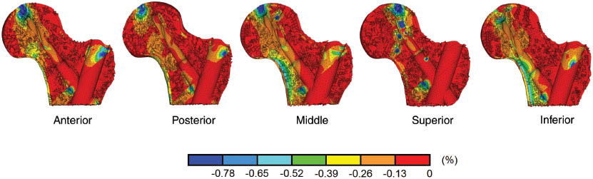
Minimum principal strain distribution in cancellous bone in proximal femur presented in percentage for five different blade positions.
TAD value, yielded bone volume, and peak von Mises stress in five different blade positions.
| Blade position | Anterior | Posterior | Middle | Superior | Inferior |
|---|---|---|---|---|---|
| TAD value | 20 mm | 23 mm | 10 mm | 17 mm | 27 mm |
| Peak von Mises stress | 437 MPa | 483 MPa | 641 MPa | 856 MPa | 492 MPa |
| Bone volume of <-0.8% yielding strain | 1438 mm3 | 857 mm3 | 1331 mm3 | 3415 mm3 | 507 mm3 |
TAD, tip-apex distance.
As for von Mises stress at the intramedullary nail, it was the highest at the medially inferior junction of the blade with the nail (Table 2). The peak value for all blade positions in sequence from highest to lowest was 856 MPa (superior), 641 MPa (middle), 492 MPa (inferior), 483 MPa (posterior), and 437 MPa (anterior).
Discussion
Many studies have investigated the placement of the lag screw in the femoral head for trochanteric fracture fixation implant. A general consensus is that the appropriate position of the lag screw should be central on the lateral view [2, 6, 21, 22, 29, 34] and either central [2, 6] or inferior on the anteroposterior view [21, 22, 29]. However, a biomechanically or clinically superior position of helical blade within the femoral head is still not well investigated. We performed a systematic analysis to assess how different helical blade positions could affect fixing of peritrochanteric fractures and the risk of cutout. To our knowledge, this study is the first computational evaluation that tried to simulate five possible helical blade positions in the femoral head seen clinically.
Generally, normal compressive strain was found to be beneficial for the bone healing process [1]. Our results revealed that inferior and posterior blade positions had the larger area of compressive strain at the fracture surface than other three positions. There was slight difference between the middle and anterior groups, and a small area of compressive strain in the superior blade position. In Helwig et al.’s work [15], by FE analysis, they compared four different implants inserted in different positions for trochanteric fracture stabilization. It was suggested that the favorable healing condition for the blade design PFNA is the caudal position. Furthermore, Hwang et al. [18] and Luo et al. [24] also suggested that the inferior position of the helical blade in the frontal plane and central position in the sagittal plane are beneficial for fixing of intertrochanteric fracture. Their result showed similar tendency with the present study.
Based on the multiaxial failure criterion, bone failure (or yielding) can be described by minimum (compressive) and maximum (tensile) principal strains. Accordingly, the risk of blade cutout was evaluated through the minimum principal strains in the cancellous bone and the yielding strain. The volume of bone strained beyond the yield strain in the proximal femur was calculated. Our results showed that superior blade position is more likely to perforate the articular surface (Table 2). The blade can be more stable in the inferior and middle positions in the head. This can be explained by a shorter lever arm when the blade is placed lower in the head. Interestingly, the TAD of the superior blade model (17 mm) in our study was found to be shorter than the inferior model (27 mm), but the volume of cancellous bone susceptible to yielding is more in the superior group, and the risk of cutout is smaller for inferior blade position. Generally, the value of the TAD is recognized as a predicting factor of fixing failure of the neck screw [2]. For a sliding hip screw, a TAD of <25 mm is critical to minimize the risk of cutout. The TADs corresponding to the two models with the superior and the anterior positions are less than the cutout value of 25 mm. However, the volume of cancellous bone susceptible to yielding is more in both superior and anterior groups, whereas the risk of cutout is smaller for inferior blade position (TAD=27 mm). Similar findings were reported in Goffin et al.’s investigation [10], although the implant involved in their study was the lag screw. They stated that a TAD>25 mm is unsuitable to be an accurate predictor of lag screw cutout. In a retrospective study involving 178 proximal fractures treated with the PFNA, Nikoloski et al. showed that no blade cutout occurred when the TAD was from 20 to 30 mm [28]. Consequently, based on our study and previous literatures, the TAD principle of <25 mm may not apply for a proper predictor of blade cutout.
The peak stress at the intramedullary nail is considered important to the function of the implant, especially the junction of the neck blade and the nail. From the biomechanical viewpoint, it is well known that a peak stress more than the yielding strength of the material can lead to plastic deformation in the implant itself. Consequently, the plastic deformation at this junction as a result of high stress will inhibit the lateralization mechanism of the blade. We reported the peak von Mises stress within the implant. The peak stress was highest in the superior position (856 MPa) which is close to the yielding stress of the biomedical Ti-6Al-4V alloy [27]. The lower stress for other positions may also be attributed to the aforementioned shorter lever length; thus, a smaller bending moment was exerted on the implant.
There are several limitations that should be considered in this study. First, all materials involved were modeled as having isotropic and linear elastic behaviors. However, it is still not clear how bone anisotropy at the tissue level (in terms of anisotropy degrees and principal axes) can be derived from clinical CT dataset. Moreover, the issue of anisotropy should mainly characterize the diaphyses of bones, while a lower degree of anisotropy can be expected of the femoral proximal epiphysis, as reported also in a paper that introduced bone anisotropy in FE simulations [12]. In Schileo et al.’s study [31], comparing experimental data and FE simulation results, they had verified that linear and isotropy FE analyses settings are able to accurately predict strains and to estimate failure risk and fractures for long bones. Accordingly, this assumption was acceptable for the purpose of comparing different blade positions. Second, the material of the bone is inhomogeneous. The calculated bone volumes should be limited to relative values for each FE model. Third, the femur used in our simulation is a subject-specific bone model. The values of all results analyzed would be changed when applied to a different individual. However, we believe that the difference in bony anatomy or material properties would not affect the major trends in our results. Moreover, the yielding strain of -0.8% of the cancellous bone was applied to vertebral body, which would not be fully comparable with the trabecular bone in the femoral head and neck. Finally, our simulation results have not been compared with experimental tests. We must restrict ourselves to relative statements. Overall, the importance of this computational analysis lies in providing certain evidence-based treatment instructions for surgeons once a blade design intramedullary nail is chosen.
In conclusion, we performed an evaluation of the biomechanical effect of different blade positions on a simulated peritrochanteric fracture by means of a CT-based 3D FE model. The results suggested that the inferior position could be an ideal choice, while the posterior position would be acceptable as well. Furthermore, the TAD may not be an appropriate predictor of helical blade cutout.
Acknowledgments
We acknowledge the financial support of the Ministry of Science and Technology of Taiwan (MOST 103-2632-E-033 -001) and the computational support from A Plus Biotechnology.
References
[1] Augat P, Burger J, Schorlemmer S, Henke T, Peraus M, Claes L. Shear movement at the fracture site delays healing in a diaphyseal fracture model. J Orthop Res 2003; 21: 1011–1017.10.1016/S0736-0266(03)00098-6Search in Google Scholar
[2] Baumgaertner MR, Curtin SL, Lindskog DM, Keggi JM. The value of the tip-apex distance in predicting failure of fixation of pertrochanteric fractures of the hip. J Bone Joint Surg 1995; 77A: 1058–1064.10.2106/00004623-199507000-00012Search in Google Scholar PubMed
[3] Bellabarba C, Herscovici D, Ricci WM. Percutaneous treatment of peritrochanteric fractures using the Gamma nail. Clin Orthop Relat Res 2000; 375: 30–42.10.1097/00003086-200006000-00005Search in Google Scholar PubMed
[4] Bhandari M, Schemitsch E, Jönsson A, Zlowodzki M, Haidukewych GJ. Gamma nails revisited: gamma nails versus compression hip screws in the management of intertrochanteric fractures of the hip: a meta-analysis. J Orthop Trauma 2009; 23: 460–464.10.1097/BOT.0b013e318162f67fSearch in Google Scholar PubMed
[5] Brunner A, Jockel JA, Babst R. The PFNA proximal femur nail in treatment of unstable proximal femur fractures – 3 cases of postoperative perforation of the helical blade into the hip joint. J Orthop Trauma 2008; 22: 731–736.10.1097/BOT.0b013e3181893b1bSearch in Google Scholar PubMed
[6] Den Hartog BD, Bartal E, Cooke F. Treatment of the unstable intertrochanteric fracture. Effect of the placement of the screw, its angle of insertion, and osteotomy. J Bone Joint Surg 1991; 73A: 726–733.10.2106/00004623-199173050-00011Search in Google Scholar
[7] Eberle S, Gerber C, von Oldenburg G, Högel F, Augat P. A biomechanical evaluation of orthopaedic implants for hip fractures by finite element analysis and in-vitro tests. Proc Inst Mech Eng H 2010; 224: 1141–1152.10.1243/09544119JEIM799Search in Google Scholar PubMed
[8] Frei HC, Hotz T, Cadosch D, Rudin M, Käch K. Central head perforation, or “cut through,” caused by the helical blade of the proximal femoral nail antirotation. J Orthop Trauma 2012; 26: e102–e107.10.1097/BOT.0b013e31822c53c1Search in Google Scholar PubMed
[9] Fritz T, Hiersemann K, Krieglstein C, Friedl W. Prospective randomized comparison of gliding nail and gamma nail in the therapy of trochanteric fractures. Arch Orthop Trauma Surg 1999; 119: 1–6.10.1007/s004020050345Search in Google Scholar PubMed
[10] Goffin JM, Pankaj P, Simpson AH. The importance of lag screw position for the stabilization of trochanteric fractures with a sliding hip screw: a subject-specific finite element study. J Orthop Res 2013; 31: 596–600.10.1002/jor.22266Search in Google Scholar PubMed
[11] Goffin JM, Pankaj P, Simpson AH. A computational study on the effect of fracture intrusion distance in three- and four-part trochanteric fractures treated with Gamma nail and sliding hip screw. J Orthop Res 2014; 32: 39–45.10.1002/jor.22469Search in Google Scholar
[12] Gomez-Benito MJ, Garcia-Aznar JM, Doblare M. Finite element prediction of proximal femoral fracture patterns under different loads. J Biomech Eng 2005; 127: 9–14.10.1115/1.1835347Search in Google Scholar
[13] Heller MO, Bergmann G, Deuretzbacher G, et al. Musculo-skeletal loading conditions at the hip during walking and stair climbing. J Biomech 2001; 34: 883–893.10.1016/S0021-9290(01)00039-2Search in Google Scholar
[14] Heller MO, Bergmann G, Kassi JP, Claes L, Haas NP, Duda GN. Determination of muscle loading at the hip joint for use in pre-clinical testing. J Biomech 2005; 38: 1155–1163.10.1016/j.jbiomech.2004.05.022Search in Google Scholar
[15] Helwig P, Faust G, Hindenlang U, et al. Finite element analysis of four different implants inserted in different positions to stabilize an idealized trochanteric femoral fracture. Injury 2009; 40: 288–295.10.1016/j.injury.2008.08.016Search in Google Scholar
[16] Hoffler CE, Moore KE, Kozloff K, Zysset PK, Goldstein SA. Age, gender, and bone lamellae elastic moduli. J Orthop Res 2000; 18: 432–437.10.1002/jor.1100180315Search in Google Scholar
[17] Hsu JT, Chang CH, Huang HL, et al. The number of screws, bone quality, and friction coefficient affect acetabular cup stability. Med Eng Phys 2007; 29: 1089–1095.10.1016/j.medengphy.2006.11.005Search in Google Scholar
[18] Hwang JH, Garg AK, Oh JK, et al. A biomechanical evaluation of proximal femoral nail antirotation with respect to helical blade position in femoral head: A cadaveric study. Indian J Orthop 2012; 46: 627–632.10.4103/0019-5413.104186Search in Google Scholar
[19] Hwang JH, Oh JK, Han SH, Shon WY, Oh CW. Mismatch between PFNa and medullary canal causing difficulty in nailing of the pertrochanteric fractures. Arch Orthop Trauma Surg 2008; 128: 1443–1446.10.1007/s00402-008-0736-1Search in Google Scholar
[20] Kopperdahl DL, Keaveny TM. Yield strain behavior of trabecular bone. J Biomech 1998; 31: 601–608.10.1016/S0021-9290(98)00057-8Search in Google Scholar
[21] Kuzyk PR, Zdero R, Shah S, Olsen M, Waddell JP, Schemitsch EH. Femoral head lag screw position for cephalomedullary nails: a biomechanical analysis. J Orthop Trauma 2012; 26: 414–421.10.1097/BOT.0b013e318229accaSearch in Google Scholar
[22] Leung KS, So WS, Shen WY, Hui PW. Gamma nails and dynamic hip screws for peritrochanteric fractures. A randomized prospective study in elderly patients. J Bone Joint Surg 1992; 74B: 345–351.10.1302/0301-620X.74B3.1587874Search in Google Scholar
[23] Lin KJ, Wei HW, Lin KP, Tsai CL, Lee PY. Proximal femoral morphology and the relevance to design of anatomically precontoured plates: a study of the Chinese population. Sci World J 2014; 2014: 106941.10.1155/2014/106941Search in Google Scholar
[24] Luo Q, Yuen G, Lau TW, Yeung K, Leung F. A biomechanical study comparing helical blade with screw design for sliding hip fixations of unstable intertrochanteric fractures. Sci World J 2013; 2013: 351936.10.1155/2013/351936Search in Google Scholar
[25] Maes M, Deboer Y, Brabants K. Failure of the titanium trochanteric Gamma nail in ununited metastatic fractures. Acta Orthop Belg 2012; 78: 552–557.Search in Google Scholar
[26] Müller M, Koch P, Nazarin S, Schatzker J. The comprehensive classification of fractures of long bones. Berlin, Heidelberg: Springer 1990.10.1007/978-3-642-61261-9Search in Google Scholar
[27] Niinomi M. Mechanical properties of biomedical titanium alloys. Mater Sci Eng A 1998; 243: 231–236.10.1016/S0921-5093(97)00806-XSearch in Google Scholar
[28] Nikoloski AN, Osbrough AL, Yates PJ. Should the tip-apex distance (TAD) rule be modified for the proximal femoral nail antirotation (PFNA)? A retrospective study. J Orthop Surg Res 2013; 8: 35.10.1186/1749-799X-8-35Search in Google Scholar PubMed PubMed Central
[29] Parker MJ. Cutting-out of the dynamic hip screw related to its position. J Bone Joint Surg 1992; 74B: 625.10.1302/0301-620X.74B4.1624529Search in Google Scholar PubMed
[30] Pu JS, Liu L, Wang GL, Fang Y, Yang TF. Results of the proximal femoral nail antirotation (PFNA) in elderly Chinese patients. Int Orthop 2009; 33: 1441–1444.10.1007/s00264-009-0776-3Search in Google Scholar PubMed PubMed Central
[31] Schileo E, Taddei F, Cristofolini L, Viceconti M. Subject-specific finite element models implementing a maximum principal strain criterion are able to estimate failure risk and fracture location on human femurs tested in vitro. J Biomech 2008; 41: 356–367.10.1016/j.jbiomech.2007.09.009Search in Google Scholar PubMed
[32] Schipper IB, Marti RK, van der Werken C. Unstable trochanteric femoral fractures: extramedullary or intramedullary fixation. Injury 2004; 35: 142–151.10.1016/S0020-1383(03)00287-0Search in Google Scholar
[33] Sommers MB, Roth C, Hall H, et al. A laboratory model to evaluate cutout resistance of implants for pertrochanteric fracture fixation. J Orthop Trauma 2004; 18: 361–368.10.1097/00005131-200407000-00006Search in Google Scholar PubMed
[34] Sowmianarayanan S, Chandrasekaran A, Kumar RK. Finite element analysis of a subtrochanteric fractured femur with dynamic hip screw, dynamic condylar screw, and proximal femur nail implants – a comparative study. Proc Inst Mech Eng H 2008; 222: 117–127.10.1243/09544119JEIM156Search in Google Scholar PubMed
[35] Wu CC, Shih CH, Lee MY, Tai CL. Biomechanical analysis of location of lag screw of a dynamic hip screw in treatment of unstable intertrochanteric fracture. J Trauma 1996; 41: 699–702.10.1097/00005373-199610000-00017Search in Google Scholar PubMed
[36] Zhou JQ, Chang SM. Failure of PFNA: helical blade perforation and tip-apex distance. Injury 2012; 43: 1227–1228.10.1016/j.injury.2011.10.024Search in Google Scholar PubMed
©2016 by De Gruyter
Articles in the same Issue
- Frontmatter
- Editorial
- The face towards nature
- Special issue articles
- Differential osteogenicity of multiple donor-derived human mesenchymal stem cells and osteoblasts in monolayer, scaffold-based 3D culture and in vivo
- Calcium phosphate/microgel composites for 3D powderbed printing of ceramic materials
- Adhesive strength of total knee endoprostheses to bone cement – analysis of metallic and ceramic femoral components under worst-case conditions
- Radiostereometric migration analysis of the Cerafit femoral stem: 28 patients followed for 2 years
- Staphylococcus epidermidis adhesion on surface-treated open-cell Ti6Al4V foams
- Research on polyvinylidene fluoride (PVDF) hollow-fiber hemodialyzer
- Research articles
- Influence of calibration method and material on the accuracy of stress distribution measurement systems
- A secure communication using cascade chaotic computing systems on clinical decision support
- Biomechanical effect of different femoral neck blade position on the fixation of intertrochanteric fracture: a finite element analysis
- Performance of a thrombectomy device for aspiration of thrombus with various sizes based on a computational fluid dynamic modeling
- Analysis of wrist bone motion before and after SL-ligament resection
- Changes of gait characteristics in a child with femoral nerve injury: a 16-month follow-up case study
- Assessing the eligibility of a non-invasive continuous blood pressure measurement technique for application during total intravenous anaesthesia