Fabrication and metrology of lithium niobate narrowband optical filters for the solar orbiter
-
Stephen D. Gensemer
 und
David Farrant
und
David Farrant

Abstract
We report on the fabrication of custom voltage tunable etalons for the SO/PHI spaceborne solar imaging instrument [A. Gandorfer, S. K. Solanki, J. Woch, V. M. Pillet, A. A. Herrero, and T. Appourchaux, J. Phys.: Conference Series 271, 012086 (2011)]. The etalons were manufactured to place a transmission maximum within 0.3 Å of the FeI emission line at 6175.0 Å. Meeting this specification requires an overall thickness specified to within ±15 nm, over a 60 mm aperture. We describe here the metrology, modelling and coating procedures we developed to achieve this.
1 Introduction
Most astronomical spectral instruments are designed to maximise the light gathering capability, so that their dispersive elements distribute the spectral signal across large detectors. In the case of solar observations, however, imaging can be done with extremely narrow band filters which still pass enough light for high quality images [1–3]. The narrowest band filters, Fabry-Perot etalons, have an extremely high angular dependence of their pass band which places constraints on their use in optical systems.
Making use of the narrow bandpass of the etalon generally requires the clear aperture to be very large, which has been a challenge for fabrication. Limitations in the thickness uniformity that is achievable by polishing have led to the development of vapour deposition as a method for correction of thickness nonuniformity, enabling us to produce substrates with thickness variations of <1 nm across 60 mm [4, 5]. Etalons made of lithium niobate (LiNbO3) have the advantage of being tunable by tilting, temperature, and voltage. In addition, their high index of refraction allows them to be made thinner than comparable air-spaced etalons, resulting in low angular sensitivity. This makes them advantageous in telescopic systems, where a wide field of view is desired. Their light weight and stability also make them well suited to spaceborne instrumentation.
Typically LiNbO3 voltage-tuneable etalons [6] are designed to be tuneable across the entire free spectral range, so that a fringe (transmission maximum) can be placed at any wavelength desired. The tuning range of such an etalon depends primarily on the thickness and the breakdown voltage, above which the crystal structure becomes depoled. The tuning range can be extended by varying the temperature and by tilting the etalon in addition to voltage tuning. However, in the Polarimetric and Helioseismic Imager for the upcoming Solar Orbiter (SO/PHI) [7], the thermal requirements of the satellite make temperature tuning of the etalon impossible, and tilt tuning is avoided to minimise pass band distortions. For these reasons, we are constrained to tunability of only a fraction of the free spectral range. The spectral window of interest is determined by the range of Doppler shifts of interest – a combination of the radial gas velocity at the solar surface and the radial velocity of the satellite in its orbit, which comes to ±26 km/s. At 6175 Å,1 this window is approximately 1.07 Å wide. The etalon was designed with a free spectral range (FSR) of 0.030 Å to ensure that only one transmission fringe overlaps the 2.7 Å wide prefilter pass band. This constraint requires that the etalon be only ≃250 μm thick. For such a thin etalon, however, the breakdown voltage prohibits voltage tuning across the entire FSR. Due to these constraints, we were motivated to develop the capability to fabricate etalons whose fringe wavelengths are specified a priori.
We report here on the fabrication of etalons using a controlled vapour deposition and measurement procedure which allows us to adjust the overall physical thickness of the etalon at will, to within <15 nm, while maintaining <1 nm thickness variation across the aperture. The structure of this paper is as follows. In Section 2 we briefly describe the fabrication process. In Section 3, the laser system is described, and in Section 4 the etalon measurement and analysis is outlined. Finally we present the results of our coating trials in Section 5.
2 Fabrication
We first produced a number of lithium niobate wafers of diameter 64 mm and thickness 250±5 μm, polished super smooth (<0.1 nm rms at spatial scales of <1 mm-1), and coated both sides with silver to a reflectivity of approximately 90%. We measured the uniformity of the thickness with a technique previously developed [8]. A representative thickness uniformity map is shown in Figure 1.
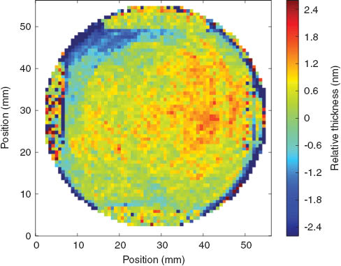
Thickness variation across a final, coated etalon. The gold contacts are visible as bars at top, bottom, left and right.
Fabry-Perot etalons support transmission maxima at normal incidence at wavelengths for which 2nd=mλ, where n is the index of refraction, d is the physical thickness, mis a positive integer that indicates the longitudinal mode, and λ is the light wavelength. In the SO/PHI [7, 9], sunlight incident on the telescope is first filtered with a 300 Å bandpass filter centred around 6175 Å. After this, a 2.7 Å filter further narrows the incident light spectrum before it strikes the etalon.
The physical fabrication starts with a poled LiNbO3 substrate of a few mm thickness [6]. The material is cut to place the extraordinary axis normal to the surface to within a few arc minutes. Thus light of any polarisation which enters the etalon normal to the surface will see only the ordinary index of refraction, n0. At this stage, the thickness is within 5 μm of the target 253 μm to ensure the correct FSR.
The polishing process can leave thickness variations across the etalon of up to 30 nm rms, which would cause the transmission fringe wavelengths to be significantly different at different locations on the etalon. This will reduce the finesse and the peak transmission when the entire aperture is used. We have developed a deterministic coating procedure to correct these variations [4, 5]. We design a coating mask which enables us to correct thickness variations down to <1 mm spatial scales by depositing a negative of the thickness map of the etalon until flatness is achieved. The etalon is then re-coated with silver and measured again to ensure that the thickness variations are reduced, and we typically achieve <1 nm rms across the clear aperture (Figure 1).
The standard construction of our etalons requires placing a multilayer coating on both sides. The final layer is a conductive coating of indium tin oxide, which is used to control the electric field in the etalon, allowing us to tune the transmission fringes via the piezoelectric effect [6].
At this point, the etalon requires a correction to its overall thickness to ensure that a transmission fringe coincides with the spectral line of interest. To this end, it is necessary to determine the precise wavelengths of the transmission fringes in the neighbourhood of the spectral line. We achieve this by making measurements of etalon transmission as a function of incident angle and laser wavelength. The published values of the refractive indices for LiNbO3 are not accurate enough for our purposes (<1 part in 105), necessitating development of a laser system.
3 Laser system
The wavelength of interest is 6175 Å. Unfortunately, diode lasers are not generally available at wavelengths to the blue of approximately 6300 Å. An option would be to use a ring dye laser, although this requires far more maintenance than a diode laser system. We took advantage of commercially available broad-area diode lasers at 6220 Å as our source. We placed the laser in an (imperfectly) sealed box, held at a slight over-pressure with dry nitrogen, and used a stack of two Peltier modules to cool the laser to -5°C. At this temperature, the peak gain of the laser shifted to 6175 Å.
As broad-area diode lasers normally emit in multiple transverse and longitudinal modes, we operate the laser below its normal lasing threshold. We provide feedback using a standard Littrow external cavity configuration [10]. We orient the lines of the grating parallel to the long dimension of the laser emission, to optimise the wavelength selectivity of the cavity. The grating was placed outside the sealed box to make adjustment of the wavelength easy.
We couple the laser output into a single mode fibre, and using a fibre splitter we send 10% of the light to a wave meter; the remaining 90% is used for the etalon transmission measurement. Our estimate of the wavelength is limited by our knowledge of a stabilised HeNe laser wavelength that was used for calibration of the wave meter, or ±30 MHz. During the measurements, we read out the laser wavelength approximately every 50–100 ms.
4 Transmission measurements
The transmission T of an etalon by light in a plane wave follows the well-known Airy function [11]:
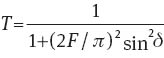
Here, F is the finesse and δ is essentially the order of the etalon, which depends upon the ratio between the optical thickness nd and the wavelength λ, modified by the angle of refraction inside the etalon θ when the etalon is tilted. When δ takes integer multiples of π, sin δ=0, and peaks in transmission occur.
Our primary concern is determining the wavelengths at which transmission maxima occur for normally incident light. Each of these wavelengths λm satisfies λm=2n(λ)d/m, where m is the integer-valued order of the etalon, and n(λ) is the wavelength-dependent index of refraction. One method for determining the values of λm would be to simply scan the laser wavelength and measure the transmission at normal incidence, but this would require laser tunability of over 3 Å, without mode hops, which cannot be achieved with available laser systems. Instead, we have mounted the etalon on a rotation stage and measure T(θ, λ) for a variety of wavelengths.
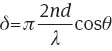
We use a Newport RGV rotation stage with a digital encoder that provides microradian control over the etalon orientation. In a typical measurement, we scan the etalon repeatedly through ±10° from normal incidence. The transmission is monitored with a photodiode, and the incident laser intensity is simultaneously monitored by a glass plate which sends a few per cent of the light to another photodiode. A typical scan of angle is shown in Figure 2. By fitting the transmission to equation 1, we determine the order corresponding to the nearest transmission maximum, and determine the wavelengths of the transmission maxima by extrapolation.
Raw data taken in a typical scan of the etalon tilt. The sample rate was 11 kHz. The rotation stage accelerates until approximately sample 800, and begins to decelerate after scan 4800. During the rest of the scan, the rotation stages uses PID control with an encoder to ensure a linear rotation in time. The blue trace (‘pickoff’) shows the relative intensity of the light incident on the etalon, as measured by the pickoff photodiode. The lower trace shows the laser wavelength as measured by the wave meter.
We scanned the etalon at 50°, and repeated the scan approximately once per second for several minutes. During this time the laser drifts through several modes due to its intrinsic thermal instability and the drift of the cavity optics. By monitoring the wavelength, we effectively sample λ at many values over approximately 1.5 Å. The wavelength can be adjusted further by tilting the diffraction grating which forms the external laser cavity. We record continuously the laser wavelength along with the transmission scans. Afterwards, we remove datasets that contain laser mode hops or multimode laser operation, and plot the results of fits to good scans as shown in Figure 3. Here we plot the fringe offset, equivalent to 2nd/λ-m, where m is an arbitrarily chosen integer indicating the index of one longitudinal mode.
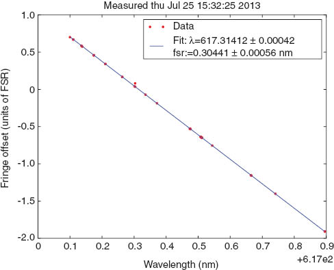
Linear fit to the fringe offset at normal incidence vs. wavelength. Transmission peaks at normal incidence appear at integer values of the fringe offset.
The data in Figure 3 was fitted to a straight line. The resulting excellent fit specifies the values of λm to within ±0.001 Å, more than adequate for these etalons. For comparison, the etalons typically have a finesse of 20–40, which puts the transmission linewidth at approximately 0.1 Å. Two comments should be made regarding the linear fit. First, an ideal, air-spaced etalon does not have transmission maxima equally spaced in wavelength, but in wavenumber or frequency. However, for the wavelength range shown in Figure 3, the approximation of linearity leads to a fitting error significantly below the statistical error in the measurements. Second, for a solid material such as lithium niobate, even a dispersion dn/dλ as small as 10-5/Å can cause a significant change in the free spectral range; at our wavelength, the FSR is shifted by over 10% by the dispersion. This will introduce an additional nonlinearity proportional to d2n/dλ2. Since the spectral range of interest to us, however, only spans approximately 5 Å, the linear approximation is sufficient.
An important check on this metrological technique was provided by a complementary transmission measurement of one of the etalons, performed at the Vacuum Tower Telescope (VTT) at Tenerife (private communication, V. Martinez Pillet). Two of the etalons, polished and silvered for a reflective finesse of 20–30, were placed in series with a grating spectrometer at the VTT, and solar absorption lines were directly used to verify the transmission wavelengths of the etalons. We tested the same etalons with our technique and found excellent agreement; both the transmission wavelengths and the finesse of the etalons agreed to within estimated errors of both experiments.
4.1 Temperature dependence
The etalon transmission peaks shift with temperature due to both thermal expansion of the wafer and to an increase in the index of refraction. Both of these effects shift the transmission maxima to the red. Since the SO/PHI instrument is designed to operate at 66°C, the transmission wavelength maxima must be known at that temperature. We have constructed a chamber for temperature measurements of the etalon, shown in Figure 4.
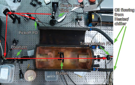
Top view of the transmission measurement layout, showing the etalon mounted inside a temperature controlled Cu oven.
A typical result of heating an etalon is shown in Figure 5. The oven is stabilised at 21°C, then slowly heated up to 66°C, where it is held for 1 h, then ramped back to room temperature. When the oven is held at 66°C, the etalon approaches its equilibrium temperature with a time constant of 12 min. By monitoring various points inside the oven and the aluminium etalon mount itself, we have verified that the etalon itself must reach a temperature within approximately 0.5°C of the setpoint of 66°C after 30 min soak with the oven at 66°C. This has also been verified with a thermal imaging camera, which determined a temperature gradient of <0.5°C between the edge and the centre of the etalon.
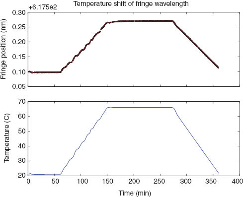
Effect of heating the etalon. The wavelength of one fringe is plotted alongside the temperature of the oven as measured by a thermometer a few cm from the etalon.
After polishing, we silver coated the etalons and measured the temperature dependence of λm. A typical result is shown in Figure 5 (red curve), in which a shift in λm of 1.607 Å is observed due to heating the etalon from 21°C up to 66°C.
Before applying the final dielectric coating on the etalons, we apply a silver coating of R≃90% and measure the etalons for thickness uniformity, measure the free spectral range as described in the previous section, and scan the temperature as above to determine the fringe positions at the operating temperature of 66°C. After the coating process was complete, we re-measured the temperature dependence of the fringe wavelengths, and observed no change within our experimental uncertainty. For these measurements, the systematic uncertainty is dominated by our uncertainty of the etalon temperature when the oven is set to 66°C (+0.1/-1°C).
4.2 Voltage dependence
Estimates based on previously tested etalons suggest that we should achieve the required tuning with a total voltage range of 3250 V. As an initial test, we measure the fringe positions with the tilt method while holding the voltage at several different values. The fringe position is seen to shift with the laser wavelength as expected, and the voltage dependence of the etalon is determined. A typical result (Figure 6) shows fringe shift of 0.353±0.001 Å/kV, and the sign allows us to determine the orientation of the crystal axis.
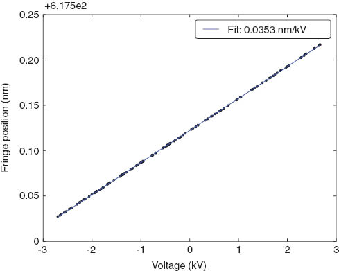
Effect on the fringe positions as a result of changing the applied voltage.
5 Coating results
After the fringe positions and the temperature dependence of the substrate are determined, we strip the silver coatings and remeasure the bare substrate to find the optical thickness of the substrate alone. From the known temperature dependence, we calculate the additional thickness required from the coatings to place a transmission fringe at the target wavelength, at 66°C.
The first coating, a stack of alternating layers of high and low refractive indices, is applied to one side, followed by a layer of indium tin oxide. After this is applied, the optical thickness of the etalon is re-measured to verify that the coating produced the expected shift in optical thickness. Finally the second side is coated in the same way, and a final measurement is made to determine the optical thickness, and to verify that the transmission maxima are shifted to the correct target wavelengths.
A summary of this process for one example etalon is shown in Figure 7. In the figure, both fringe wavelength and optical thickness of the etalon increase in the upward direction. The first arrow and the first red (square) data point indicate the effect of heating the silvered etalon from 21°C to 66°C. After stripping off the silver coating, the optical thickness decreases, and the thickness is again re-measured after each of the dielectric coatings is applied. We have applied this procedure to five etalons in total, and were successful each time in placing the fringe within 0.23 Å of the target wavelength (with a standard deviation of 0.167 Å).
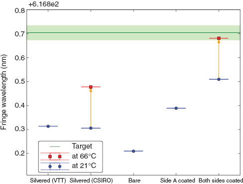
Changes in fringe positions as the etalon thickness changes through the coating process. The effect of heating was measured when the etalon was silvered and again after the ITO coating was applied to both sides. The green line (and shaded region) indicates the target fringe position.
6 Conclusion
We have developed a technique for fabrication of etalons whose absolute thickness, approximately 250 μm, is controlled to <10 nm, maintaining a thickness uniformity of <1 nm over the 60 mm aperture. This enabled us to provide electrically tuned Fabry-Perot etalons for the SO/PHI space-borne instrument for solar astronomy. The technique can be adapted to other optical elements whose absolute optical thickness must be precisely adjusted, and is not limited to lithium niobate substrates, since the thickness correction is done with vapour deposition during the application of the dielectric coating.
- 1
For practical reasons the wavelength measurements were made, and are quoted here, in vacuum.
Acknowledgments
We kindly thank V. Martinez Pillet for measurements undertaken at the VTT; K. Green, J. Seckold, and W. Stuart at CSIRO Precision Optics for fabrication of the wafers; A. Chtanov and S. Dligatch at CSIRO Precision Optics for preparation of the coatings; and M. Gross for design of the oven. This work was supported by the Max Planck Institute for Solar System Research and the Future Manufacturing Flagship at CSIRO.
References
[1] T. Chandrasekhar, C. Debiprasad, J. N. Desai and N. M. Ashok, Opt. Eng. 27, 121088 (1988).Suche in Google Scholar
[2] C. D. Prasad and S. Gosain. Exp. Astron. 13, 153–158 (2002).10.1023/A:1025564731907Suche in Google Scholar
[3] U. Schuhle, Proc. 2nd Solar Orbiter Workshop, ESA SP-641 (2007).Suche in Google Scholar
[4] J. Arkwright, I. Underhill, N. Pereira and M. Gross, Opt. Express 13, 2731–2741 (2005).10.1364/OPEX.13.002731Suche in Google Scholar
[5] J. W. Arkwright, Appl. Optics 46, 6375–6380 (2007).Suche in Google Scholar
[6] C. H. Burton, A. J. Leistner, and D. M. Rust, Appl. Optics 26, 2637–2642 (1987).Suche in Google Scholar
[7] A. Gandorfer, S. K. Solanki, J. Woch, V. M. Pillet, A. A. Herrero and T. Appourchaux, J. Phys.: Conference Series 271, 012086 (2011).10.1088/1742-6596/271/1/012086Suche in Google Scholar
[8] D. I. Farrant, J. W. Arkwright, P. S. Fairman and R. P. Netterfield, Appl. Optics 46, 2863–2869 (2007).Suche in Google Scholar
[9] P. V. S.C. Tripathy, Meeting on “Probing the Sun with High Resolution” (2001: Udaipur Solar Observatory), 2001.Suche in Google Scholar
[10] C. E. Wieman and L. Hollberg, Rev. Sci. Instrum. 62, 1–20 (1991).Suche in Google Scholar
[11] G. Hernandez, Fabry-Perot Interferometers. (Cambridge University Press, 1988).Suche in Google Scholar
©2014 THOSS Media & De Gruyter Berlin/Boston
This work is licensed under the Creative Commons Attribution-NonCommercial-NoDerivatives 3.0 License.
Artikel in diesem Heft
- Frontmatter
- Community
- News from the European Optical Society
- Conference Notes
- Conference Calendar
- Topical Issue: Optics for Astronomy / Guest Editors: Jan Burke, Andrew Rakich and Jim Burge
- Editorial
- Optics for astronomy – Editorial
- Review Articles
- Active optics with a minimum number of actuators
- Highly sensitive telescope designs for higher contrast observations
- Replicated spectrographs in astronomy
- Ultra-smooth finishing of aspheric surfaces using CAST technology
- Hydroxide catalysis bonding for astronomical instruments
- Research Articles
- Fabrication and metrology of lithium niobate narrowband optical filters for the solar orbiter
- A method for the use of ellipticities and spot diameters for the measurement of aberrations in wide-field telescopes
- Deflectometric measurement of large mirrors
- The Four-Laser Guide Star Facility: Design considerations and system implementation