Method and Application of Operational Architecture Modeling Based on Information Flow Analysis
-
Yinghui Yang
 ,
Jianhua Li
,
Jianhua Li

Abstract
To strengthen operational process analysis and normalize information requirements description in systemic operations based on information systems, a new operational architecture modeling method is proposed from the perspective of information flow analysis. An operational architecture modeling framework based on information flow analysis is established by referring to American department of defense architecture framework (DoDAF V2.0). Concepts of entities, relationships, attributes and mapping rules are defined. Operational activity model, operational nod model and information alternation model are constructed. Finally, aerial assault operation is taken as an example to demonstrate the modeling process. Simulation results show that operational process analysis is more refined and information requirement descriptions are more visible, normal and clear, which validate the feasibility and validity of the method and models.
1 Introduction
An operational system consists of many combat systems keeping to certain command and organization relationships and functional mechanisms. As a key support of modern warfare and an essential part of military construction and development currently, it generally possesses quite complex architecture[1]. Operational architecture is the modeling description of components’ structure, inherent relationship, rules and guides, which is the foundation of operational system research and has great significance in optimizing architecture and improving combat capabilities.
At present, research achievements about architecture modeling mainly concentrate on view analysis, model construction, structure description, requirement demonstration, data validation, etc. In the research fields above, much progress has been made. In the view analysis, functional mechanism and evolvement process of architecture are described from views of operation, system, service and technology[2 –4]. In the model building, by applying architecture modeling methods based on mission[5], metamodel[6], structure analysis[7], and so on, equipment systems and military information systems are modeled and simulated. In the structure description, aiming at researching objects’ specialty, methods oriented mission capability[8, 9] and service[10], are given to describe equipment systems and ad-hoc networks formally. In the requirement demonstration, military requirement demonstration frameworks are designed to analyze requirements for operations, capability, service and information during the process of operational activities and system development[11, 12]. In the data validation, consistency validation methods based on describable logic[13], DM2[14], and so on, are put forward to solve information inconsistent problem of multi-view products caused by architecture development. These research achievements have improved cognitive level of architecture modeling, but don’t pay enough attention on real operational actions and information alternation relationships. Therefore, much research space still exists in decomposing operational process hierarchically and describing military requirements normatively.
There are various information flows impenetrating whole operational process, which plays an important role on constructing combat systems and distributing battlefield resources. Hence, taking information flows as breakthrough point to research operational activities and analyze information alternation relationships, can not only describe complex types, contents and directions of information flows exactly, but also make up the problems of lacking systematization and hierarchy in current architecture modeling, which provide good foundations for operational architecture optimization.
Based on the analysis above, a new operational architecture modeling method is proposed from the perspective of information flow analysis. In Section 2, operational architecture modeling framework based on information flow analysis is established by referring to American department of defense architecture framework (DoDAF V2.0). In Section 3, architecture modeling method based on information flow analysis is put forward and three models are presented, including operational activity model, operational node model and information alternation model. In Section 4, general process of operational architecture modeling is demonstrated combined with aerial assault operation. Finally, conclusions are given.
2 Operational Architecture Modeling Framework Based on Information Flow Analysis
2.1 Analysis Viewpoints of DoDAF V2.0
DoDAF V2.0 mainly deploys around data, models and views, and emphasizes collection, organization and maintenance of data as well as information[4]. As kinds of architecture data selected, views describe collected data and outputting information during developing process, which are displayed visually by control panels, texts, figures, etc. Figure 1 gives all the analysis viewpoints of DoDAF V2.0.
The current researches on architecture modeling based on DoDAF V2.0 describe architectures visually and normatively, mainly from viewpoints of operations, system, data and information. However, most of them analyze operational process, system and information individually, not depicting complex information alternation relationships among real operational processes and implementing units exactly.
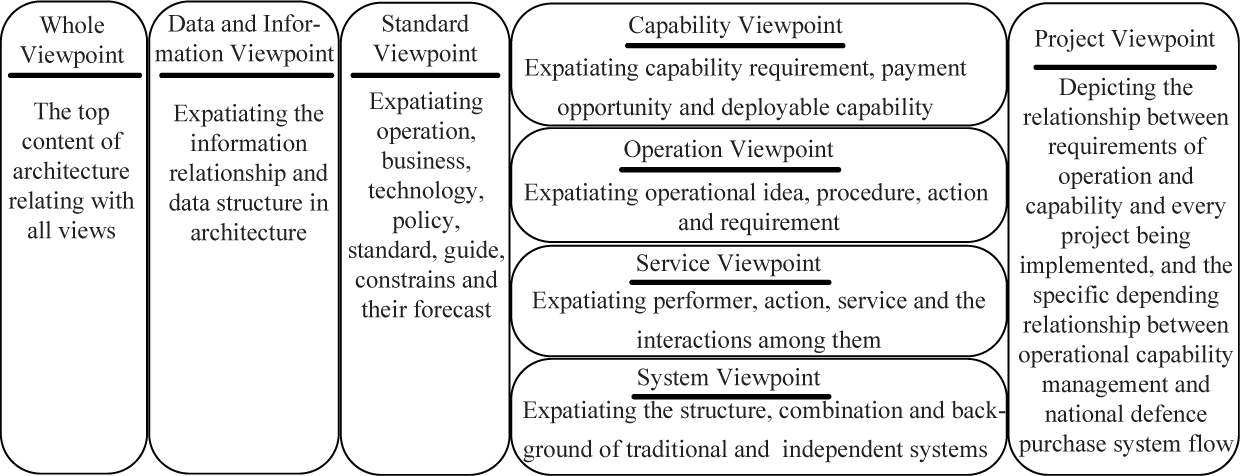
Analysis viewpoints of DoDAF V2.0
2.2 Views of Operational Architecture
Referring to multi-view theory of DoDAF V2.0[4], factors, such as operational requirement, system design and technology support, are considered synthetically to divide some parts of DoDAF V2.0 products into information flow view again when building operational architecture, namely, operational architecture view based on information flow analysis. The relationships between information flow view and original views are shown in Figure 2[5, 8]. Operational architecture modeling through information flow view in different battlefield environment, lays an emphasis on macroscopical control of the whole combat systems from viewpoints of operation, technology and system. In addition, it also reflects specific demands of information alternation and system functional connection noticed by different decision-makers especially.

Relationships between different views
2.3 Framework of Operational Architecture Modeling
The framework of operational architecture modeling based on information flow analysis, reflects the combat concept of information dominant and functional pattern of information flow driving materials flow and leading energy flow in systematic operations.
In specific modeling process, information flow is taken as main line and operational task as starting point. Following the order of “task-activity-node-information”, entities, relationships and attributes are defined, and mapping rules and modeling steps are normalized. Entities are decomposed hierarchically. Actions and information alternation process are analyzed accurately. Then, architecture model is built in which information alternation relationships are sorted, information exchanging attributes are explicated and information transferring process and alternation relationships between different activities and nodes are described clearly. Based on the analysis above, the framework of operational architecture modeling based on information flow analysis is given in Figure 3.
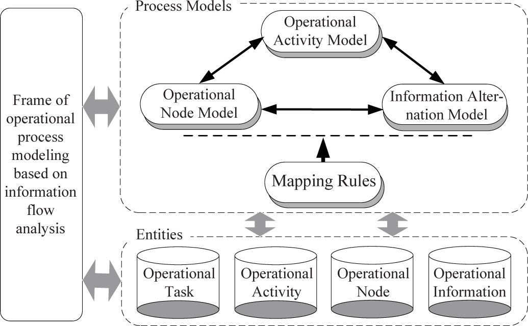
Framework of operational architecture modeling
The framework above consists of two parts: Entities and architecture models. Among them, entities are main elements of operational architecture, which provide basic support of various models. Mapping rules offer essential modeling principles.
3 Architecture Modeling Method Based on Information Flow Analysis
Method of operational architecture modeling based on information flow analysis, takes information flow as center and builds several models of operational process hierarchically by analyzing entities, relationships and attributes according to certain mapping rules. Besides, it also describes alternation relationships and flowing demands of different kinds of information in combat systems normatively.
3.1 Basic Definitions
3.1.1 Entities
According to the framework of operational architecture modeling, entities mainly consist of operational information, nodes, activities and tasks. Because modern warfare is a complex and huge system with typical networked characteristics, complex network theory can be used to define entities.
Definition 1
Entities are objects dealing information which are traced by task demands. They can be expressed as CE = {CEi|i ∈ [1, m]}, where m is the number of entities[12].
Definition 2
Operational information is effective reflections of different battlefield objects’ characteristics, states, developments and changes which are produced in operational process. They can be expressed as
Definition 3
Operational nodes are entities collecting, delivering and dealing data as well as information in operations. They can be expressed as
Definition 4
Operational activities are ordered action sets of various nodes for specific tasks. They can be expressed as
Definition 5
Operational tasks are ordered activity sets of various nodes for specific purposes. They can be expressed as CEtask = {Ti|i ∈ [1, T0]}. As to any task Ti, there is equation Ti = Ak, 1 ∪ Ak,2 ∪ ⋯ ∪ Ak, i where k ∈ [1, H0], j ∈ [1, A0].
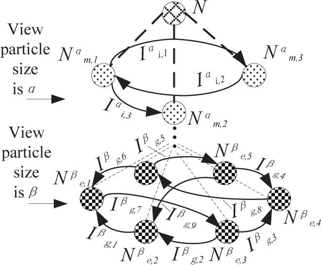
Entities with certain kinds and limited number are basics of architecture views. Corresponding connection relationships of entities between other architecture views are shown in Figure 4[4, 8].

Entities connections between different architecture views
3.1.2 Relationships and Attributes
Definition 6
Relationships are flow of data or information between different entities. They are usually noted by information requirement lines and expressed as CR = {CRi|i ∈ [1, n]}, where n is the number of connection relationships.
Definition 7
Attributes are characteristics determined by entities and relationships in information exchanges. They can be expressed as CP = {CPi|i ∈ [1, t]}, where t is the number of attributes.
Generally, entities don’t exist solely. Besides, they connect each other with specific attributes. Basic grammar rules of architecture modeling are commonly constituted by entities, relationships and their attributes, which are foundations of architecture’s grammar normality and information integrity. The relationships between entities are shown in Figure 5. A group of three-variable relationships is composed of operational activities, nodes and information around a specific task. It can be expressed as CR = ϒ (CEacti, CEnode, CEinfo), which is the key of operational architecture modeling.

Relationships between entities
3.1.3 Mapping Rules
Definition 8
Mapping rules are basic criterions for different entities when generating associated relationships. They include four kinds, namely, activity → activity, activity→node, node→activity and node→node[8–12], and can be expressed as CF = {CFi|i ∈ [1, p]} where p is the number of rules.
Rule 1 Activity→activity information mapping
Activity→activity information mapping reflects the input, output and control information of an operational activity determining particular alternation information between activities. It is a direct mapping and can be expressed as a three-variable function of original activity, target activity and the information alternated, namely,
Set view particle size as θ.
Select information
Take information
Complete the activityactivity information mapping between
Then, Rule 1 can be shown as Figure 6.

Activity→activity information mapping
Rule 2 Activity→node information mapping
Activity→node information mapping reflects output pointing nodes of operational activities determining all the nodes involved in activities. It is a composition mapping and can be expressed as a four-variable function of activity, the input, output and control nodes, namely,
Set view particle size as ψ.
Select activity
Similarly, the nodes set controlling
Take nodes set
Complete the activitynode information mapping of
Then, Rule 2 can be shown as

Activity→node information mapping
Rule 3 Node→activity information mapping
Node→activity information mapping determines the activities with given node involved. It is a composition mapping and can be expressed as a multi-variable function of node and activities it involved, namely,
Set view particle size as υ.
Select node
Associate node
Complete the nodeactivity information mapping of
Then, Rule 3 can be shown as Figure 8.

Node→activity information mapping
Rule 4 Node→node information mapping
Node→node information mapping determines associating relationship and alternation information among nodes. It is a direct mapping and can be expressed as a three-variable function of generating node, consuming node and the information alternated, namely, CF4 =
Set view particle size as π.
Select information
Protract information requirement line from node
Complete the node→node information mapping between node
Then, Rule 4 can be shown as Figure 9.

Node→node information mapping
3.2 Modeling Flow
According to mapping rules, activities and information are hierarchically decomposed to build models of operational activity, node and information alternation, respectively. The specific flow is shown in Figure 10[15].

Basic flow of operational architecture modeling
Step 1 Clarify operational task and decompose operational activities and nodes hierarchically according to the difference of view particle sizes.
Step 2 According to mappings of activity→activity, activity→node and node→activity, determine the information alternated between activities, and sort nodes involved in activities, and clarify activities with nodes involved and build operational activity model combined with hierarchical structures of activities and nodes.
Step 3 According to node→node mapping, determine the information alternated between operational nodes and build operational node model combined with hierarchical structure of nodes.
Step 4 According to models of operational activity and node, build information alternation model.
Step 5 According to three models above, design operational architecture based on information flow analysis.
3.3 Model Construction
3.3.1 Operational Activity Model
Operational activity model reflects hierarchical information alternating situation among operational activities. It can be expressed as a three-variable function of activity, information and node, which can be noted as OAM = Θ ( CEacti, CEinfo, CEnode). When view particle size is set as χ, activities can be divided into ε levels where ε ≤ H0. Here, activity set is

Operational activity model
3.3.2 Operational Node Model
Operational node model reflects hierarchical information requirement relationships among operational nodes. It can be expressed as a two-variable function of node and information, which can be noted as ONM = Φ (CEnode, CEinfo). When view particle size is set as α, nodes can be divided into ϕ levels where ϕ ≤ J0. Here, node set is and information set among nodes is
Operational node model
3.3.3 Information Alternation Model
Information alternation model reflects information alternating relationships among nodes in operational process. It can be expressed as a three-variable function of information, activity and node, which can be noted as OIM = Ψ (CEinfo, CEnode, CEacti). When view particle size is set as ε, select information

Operational information alternation model
4 Example Analysis
We take air assault operation in the background of systemic operations as an example to build operational architecture models based on information flow analysis.
4.1 Process of Air Assault Operation
Air assault operation is the operational action which attacks enemy targets on the ground or at sea from air. It mainly includes intelligence reconnaissance, electronic interfering and assault operation. In the intelligence reconnaissance, reconnoitering forces, such as radar, electronic confronting and technology reconnoitering, are applied synthetically to collect intelligence about enemy aviation bases, combat plans and air-defense weapons, especially precise locations, shape characteristics, number and air-defense capability of big radars and air-defense missiles positions. In the electronic interfering, enemy electronic equipments are suppressed, interfered and deceived severely. In addition, important radar stations, command and control (C2) systems and electromagnetism targets are attacked by anti-radiation. As the result, a strong interfering region is formed to blind enemy radars and weaken C2 systems and air-defense weapon systems. In the assault operation, under the order and coordination of command post, each operational unit attacks enemy key targets and important positions following scheduled plans, especially enemy air-defense systems and air counterattack systems. During and after the first assault, reconnoitering means, such as satellite, aviation and ground reconnoitering, are used to check out attack effects and enemies’ deployment changes timely. Operational units can adjust subsequent assault targets and methods by analyzing reconnaissance results. The important targets damaged are prior to be attacked continuously and preferentially for thorough ruin and being suppressed long time[12]. The basic operational process is shown in Figure 14.

Basic process of air assault operation
Air assault operation (AAO) can be divided into intelligence reconnaissance (IR), electronic confronting (EC) and assault operation (AO). Operational nodes can be divided into intelligence security nodes (ISN), C2 nodes (C2N) and fire attack node (FAN). The ISN include radar force (RF), electronic confronting force (ECF), intelligence center (IC) and warning satellite (WS). The C2N include united command post (UCP) and regional command post (RCP). The FAN is aviation force (AF). Operational information can be divided into intelligence security information (IIS), combat command information (ICC) and weapon control information (IWC).
4.2 Operational Activity Model
According to the difference of view particle sizes, IR can be divided into warning & detecting (WD), identification (ID) and information amalgamation (IA). EC can be divided into electronic reconnaissance (ER), electronic interference (EI) and fire destruct (FD). AO can be divided into standoff assault (SA) and precision assault (PA). AF node can be divided into command post (ACP), warning & command plane (WCP), interfering formation (IF), suppressing formation (SF), assaulting formation (AF) and covering formation (CF). RF node can be divided into command post (DCP), camp a (CA)b (CB) and c (CC). The hierarchical structures of activities and nodes are shown in Figure 15.

Hierarchical structures of activities and nodes
According to mapping rule 1, namely, activity→activity information mapping, two inner mappings of intelligence reconnaissance activity, two inner mappings of electronic confronting activity, one inner mapping of assault operation activity and three mappings between three kinds of operational activities are built. The eight activity→activity mappings are shown in Table 1.
Mappings among activities
| Original Activity | Target Activity | Requirement Line | Information Style |
|---|---|---|---|
| IR | EC | IR→EC | IIS |
| IR | AO | IR→AO | IIS |
| EC | AO | EC→AO | IIS |
| WD | ID | WD→ID | IIS |
| ID | LA | ID→LA | IIS |
| ER | EI | ER→EI | IIS |
| EI | FD | EI→FD | IIS |
| SA | PA | SA→PA | IIS |
According to mapping rules 2 and 3, namely, activity→node and node→activity information mappings, eleven activity→node mappings and sixteen node→activity mappings are built. The twenty-seven mappings among activities and nodes are shown in Table 2.
Mappings among activities and nodes
| Activity | Implementing Nodes |
|---|---|
| IR | RF/ECF/IC/WS |
| EC | ECF/AF |
| AO | AF |
| WD | CA/CB/CC/ECF/WS |
| ID | CA/CB/CC |
| LA | IC |
| ER | ECF/WCP/IF/CF |
| EI | WCP/IF/CF |
| FD/SA/PA | WCP/IF/SF/AF/CF |
Based on the analysis above, activity model for air assault operation is built as shown in Figure 16.
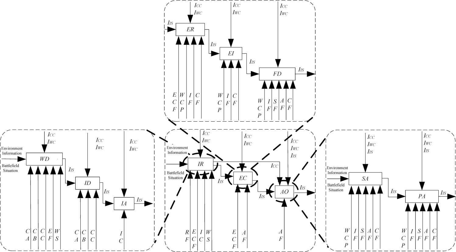
Hierarchical structures of activities and nodes
4.3 Operational Node Model
According to mapping rule 4, namely, node→node information mapping, twenty-three inner mappings of fire attack node set, fourteen inner mappings of intelligence security nodes set, two inner mappings of C2 nodes and twenty-one across mappings among three operational nodes set are built. The sixty node→node mappings are shown in Table 3.
Mappings among operational nodes
| Original Node | Target Node | Information Style |
|---|---|---|
| UCP | RCP/AF/IC | ICC |
| RCP | UCP/AF/RF/IC | ICC |
| RCP | ECF/WS | ICC/IWC |
| RF/ECF/WS | IC/AF | IIS |
| IC | UCP/RCP/AF | IIS |
| AF | RF/ECF/IC/WS | IIS |
| AF | UCP/RCP | ICC |
| DCP | CA/CB/CC | ICC/IWC |
| CA/CB/CC | DCP | IIS |
| ACP | WCP | IIS/ICC/IWC |
| WCP | ACP | IIS |
| WCP | IF/SF/AF/CF | IIS/ICC/IWC |
| IF/SF/AF/CF | WCP | IIS |
Based on the analysis above, node model for air assault operation is built as shown in Figure 17.

Node model for air assault operation
4.4 Information Alternation Model
Based on the operational activity and node models above, information alternation model is built with main line of information types. In this model, according to implementation process of air assault operation, original nodes, targets nodes, generating activities and consuming activities of different information are analyzed orderly. Information transferring course and alternation relationships are sorted clearly. Information alternation model for air assault operation is shown in Figure 18.
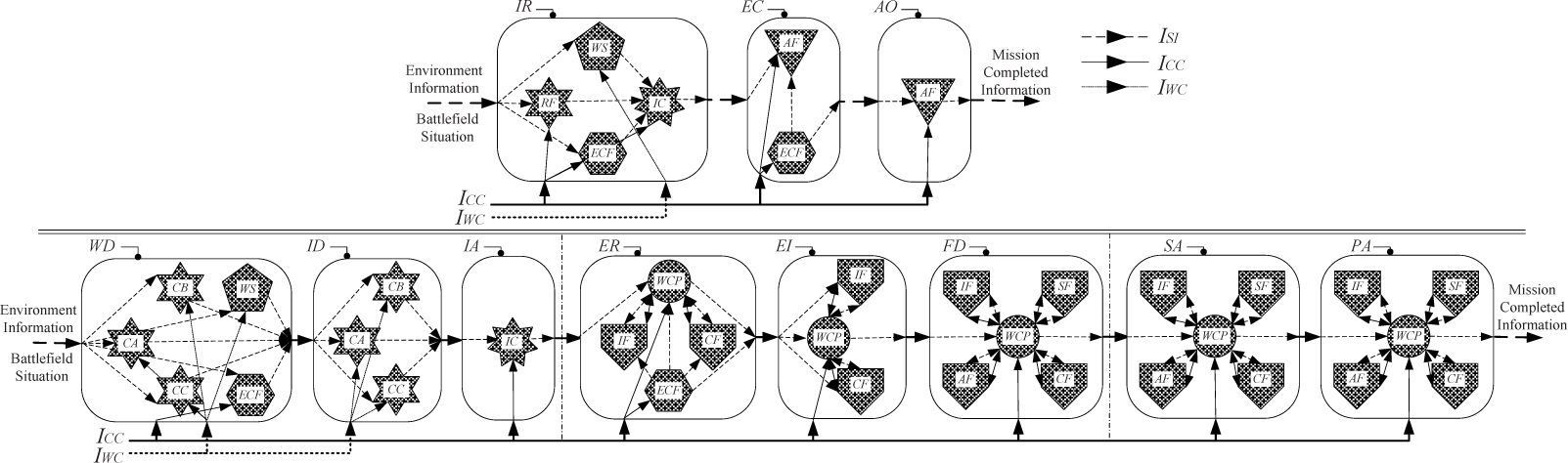
Information alternation model for air assault operation
Taking information flow as main line, architecture modeling considers synthetically various factors, such as operations, information, system and technology, and clarifies operational process analysis further, which outstand significant effects of different information and realize the architecture developing strategy of information flow centered and process oriented. Compared with architectures built simply from viewpoints of operations, service and capability before[15–17]), the operational architecture above displays elements more comprehensively, analyzes modeling results more visually, depicts information relationships more clearly and describes requirements more normally, which promote the use and exchange of architecture information effectively and expatiate the operational concept of information dominant in modern warfare adequately.
5 Conclusions
In this paper, entities, attributes and relationships are defined and mapping rules among activities and nodes are proposed. Then operational architecture models are built, which provide a new idea and method for operational architecture modeling. The research is helpful to enhance normality of architecture analysis and consistency of information requirement description. Additionally, it also lays good foundation for subsequent research work, such as operational architecture optimization and software development.
Acknowledgements
The authors gratefully acknowledge the editor and two anonymous referees for their insightful comments and helpful suggestions that led to a marked improvement of the article.
References
[1] Waters J, Ceruti M G. Modeling and simulation of information flow: A study of infodynamic quantities. The 15th International Command and Control Research and Technology Symposium (ICCRTS 2010), 2010: 178–183.Search in Google Scholar
[2] Dajsuren Y. DAutomotive architecture description and its quality. ESEC/FSE’13, 2013: 727–730.10.1145/2491411.2492403Search in Google Scholar
[3] Suter B W. Wireless computational networking architectures. Rome: Air Force Research Laboratory, 2013.Search in Google Scholar
[4] DoD Acrhitecture Framework Working Group. DoD architecture framework version 2.0. US: Department of Defense, 2009.Search in Google Scholar
[5] UK Ministry of Defense. UK ministry of defense architectural framework (MUUAF) v1.2.004.UK Ministry of Defense, 2010.Search in Google Scholar
[6] Xie W C, Luo X S, Luo A M. Meta-model based modeling of military information system architecture. Journal of National University of Defense Technology, 2012, 34(1): 82–87.Search in Google Scholar
[7] Zhang J Y, Liu J X, Luo X S. System modeling simulation based on architecture analysis. Military Operations Research and System Engineering, 2011, 25(3): 47–51.Search in Google Scholar
[8] Xu B Q, Zhang L C. Muti-dimensional architecture modeling for cyber physical systems. Advances in Computer Science and Its Applications, 2013 (CSA 2013), 2014: 101–105.10.1007/978-3-642-41674-3_16Search in Google Scholar
[9] Wang B Y, Zhao X Z, Wang J. Optimizing the combat network on the anti-ship of vessel formation. Systems Engineering — Theory & Practice, 2013, 33(9): 2354–2361.Search in Google Scholar
[10] Lewis G. Architecture and design of service-oriented systems: Goals. Pittsburgh: Carnegie Mellon University, 2013.Search in Google Scholar
[11] Kaufmann J R, Hand J R. Integrating renewable engrgy requirements into building energy codes. National Laboratory, 2011.10.2172/1024089Search in Google Scholar
[12] Yang Y H, Li J H. Campaign information requirement analysis based on architecture modeling. Military Operations Research and System Engineering, 2012, 26(4): 21–24.Search in Google Scholar
[13] Keen T R, Dykes J D. Model verification and validation using graphical information systems tools. Arlington: Naval Research Laboratory, 2013.10.21236/ADA587422Search in Google Scholar
[14] Li Z H, Tan X S, Wang H, et al. Data consistency verification of architecture based on DM2. Systems Engineering and Electronics, 2013, 35(2): 357–361.Search in Google Scholar
[15] Jepperson D B. Using model based systems engineering and the systems modeling language to develop space mission area architectures. Monterey: Naval Postgraduate School, 2013.Search in Google Scholar
[16] Alexander M G. Requirement assurance: A verification process. Langley Research Center, Hampton, Virginia, 2011.Search in Google Scholar
[17] Thakor S, Chen T, Grant A. Bounds for network information flow with correlated Sources. The 12th Annual Australian Communications Theory Workshop, 2011: 43–48.10.1109/AUSCTW.2011.5728735Search in Google Scholar
© 2016 Walter de Gruyter GmbH, Berlin/Boston
Articles in the same Issue
- Decision-Making of an Integrated Supply Chain with Hybrid Sales Channels to Cope with Dual Cost Disruptions
- Impacts of Hyperbolic Discounting on Inventory Replenishment Policy Under Inflation
- Method and Application of Operational Architecture Modeling Based on Information Flow Analysis
- Impact of Repatriate’s Knowledge Transfer on Enterprise Performance: The Mediating Effect of Ambidexterity Innovation
- Inventory and Pricing Decisions Under Wholesale Price Contract with Social Preferences
- Smoothing Approximation to the Square-Root Exact Penalty Function