
Compact low-pass filter (LPF) with wide harmonic suppression using interdigital capacitor
-
Arpita Mandal
 and
Tamasi Moyra
and
Tamasi Moyra

Abstract
In this article, a compact microstrip low-pass filter (LPF) with low in-band insertion loss and a wide attenuation band is recommended. The structure is modeled using two rectangular-shaped open resonators (ORs) loaded with multiple sections of the interdigital capacitor. The proposed LPF has a cut-off frequency of 1.5 GHz, a passband insertion loss of 0.35 dB, and an electrical circuit size of 0.02 λ g 2. In the ground plane, two dissimilar defected ground structures (DGSs) are introduced to generate additional attenuation poles for enriching the stopband performance of the LPF. The harmonics suppression is achieved up to 15 GHz with tenth harmonic suppression and relative stopband rejection of almost 165%. The EM simulated results show a well-matched behavior with the experimental ones. The proposed LPF can be used for global positioning systems (1500 MHz), telecommunications (1600 MHz), and audio broadcasting (1400 MHz) applications.
1 Introduction
Microwave low-pass filters (LPFs) can be vital components in advanced microstrip technology for removing unwanted high frequency and intermodulation signals. The compact, sharp roll-off rate, low fabrication cost, and much wider rejection bandwidth are the important parameters for designing planar filters [1], [2], [3], [4], [5], [6], [7], [8], [9], [10], [11], [12], [13], [14], [15], [16], [17], [18], [19], [20], [21], [22], [23], [24], [25], [26], [27], [28]. Moreover, various techniques are presented to design low loss miniaturized LPF circuits [1], [2], [3], [4]. The multi-resonator identical cells could be cascaded forming a tapered structure to design a wide stop bandwidth LPFs [5, 6]. However, these structures bring the problem of circuitry and more in-band loss in the passband region. To achieve the demand of miniaturized LPFs circuits, open complementary split-ring resonators (SRR) were proposed [7]. Although, the circuit complexity was enhanced due to three-dimensional structures. The stepped-impedance modified structures could also be very useful for filter performance improvement [8], [9], [10]. A hairpin structure was centrally embedded with the m-shaped stepped impedance resonator unit for exhibiting excellent band suppression performance (40 dB out of band rejection) [9]. Whereas, the passband response suffers from a gradual fall which results in a poor roll-off factor. Open resonators were used to design elliptical-shaped LPF acquiring compactness and wide stopband [11]. Usually, interdigital capacitor circuits with bandpass response were often proposed by many researchers [12], [13], [14], [15], [16] but on the other hand, few works were found in LPF design using such circuits. In an interdigital capacitor, a small gap is present between the copper conductors which increases the capacitance of the circuit. The variation in the finger length of these structures improves the susceptance and coupling behavior between them. Meanwhile, implementation of defected ground structures (DGS) and complementary split-ring resonator (CSRR) DGS [17, 18] enhanced the filter stopband performance and could mitigate the problem of circuit complexity [19], [20], [21], [22], [23], [24]. Similarly, SRR and CSRR based filters were designed for their miniaturized circuits [26], [27], [28], [29]. However, in [30], CSRR is used for harmonic reduction to acquire good sharpness factor but, the stopband performance is very narrow and also other characteristics of the filter are limited. In the proposed work, designing of LPF with wide attenuation band is taken into consideration.
This article proposes a low-cost 1.5 GHz LPF with compactness, highly selective, low insertion loss, and broad attenuation band to pass the low-frequency signals for L-band applications. The two rectangular-shaped resonators loaded with interdigital capacitor units is used to design the proposed structure. The resonators open at similar ends are connected by multiple sections of interdigital capacitor which introduces a narrow notch band. The notch band is extended to lowpass filter response by eliminating the higher spurious frequencies for wide stopband performance. The ground plane is incorporated with two U-shaped dumbbell DGSs and two modified CSRRs which helps to get a wideband response with an average rejection level of almost −20 dB up to 15 GHz without increasing the circuit size. The proposed LPF structure is fabricated on the FR4 substrate which is readily available and of low cost. The height (h) of the substrate is 0.8 mm having a loss tangent (tan δ) of 0.02 and dielectric constant (ϵ r) of 4.4. The lumped circuit of the proposed LPF is also derived and simulated. The electromagnetic simulated, circuit and measured responses shows a well-matched behavior among each other. In the last section, the proposed structure is compared with the previous related works.
2 Filter analysis and design methodology
The designing and analysis of the filter are initiated from the comparative analysis of a generalized third-order Chebyshev LPF response. The structure presents two rectangular-shaped ORs open-ended at similar ends loaded with three units of the interdigital capacitor (Figure 1A). Consequently, the electrical length of the structure is increased within a small region. A 0.4 mm narrow space gap (S g) and finger width (F w) of 0.5 mm is maintained among the interdigital arms. Although the lengths of the interdigital capacitor in separate sections of the OR are different, constant S g and F w are maintained. The cut-off frequencies and roll-off factor can be varied by changing the S g and F w of the interdigital capacitor. Figure 1B plots the different cut-off frequencies and some variations in stopband obtained by varying the S g slightly among the interdigital fingers. According to the parametric study, it is found that the gap is inversely proportional to the cut-off frequency of the proposed LPF (Figure 1C). A strong electromagnetic coupling is produced due to the narrow S g between the interdigital arms which in turn increases the capacitive effect to obtain the desired operating frequency and bandwidth of the proposed filter. The proposed LPF design methodology is explained in its subsequent steps and is depicted in Figure 2(A-D) chronologically. A systematic approach for obtaining the frequency responses of the proposed LPF is presented. The structure is established using two ORs loaded with interdigital capacitor units achieving a notch band response. Initially, the resonators are connected internally through these interdigital arms and the desired cut-off frequency is found at 1.5 GHz. A notch is introduced at 2.8 GHz with a gradual fall and narrow bandwidth (Figure 2A). The attenuation zero is obtained at 0.7 GHz and an attenuation pole at 2.8 GHz. Later on, for widening the stopband width with improved passband response, the two different DGSs (U-shaped dumbbell DGS and modified CSRR) are etched from the ground metallic plane to introduce a small amount of capacitance and an extra inductance and in the microstrip transmission line. It can be found that the inclusion of these DGSs structures creates additional attenuation zero in the passband and attenuation poles in the stopband region. Likewise, a five-pole LPF is realized with a cut-off frequency of 1.5 GHz (Figure 2D). Finally, the resulting structure provides the proposed lowpass filtering response with wide harmonic suppression. In Figure 2B, it is shown that the single unit U-shaped dumbbell DGS and modified CSRR unit provides two transmission zeroes at 5.18 and 3 GHz, respectively. The single unit DGSs cells are placed on the backside underneath the microstrip transmission line, while the conductor strip is on the top side for excitation and the individual frequency responses are obtained. In the complete structure (Figure 2C) of the proposed LPF, two units of U-shaped dumbbell DGS and modified CSRR are etched from the metallic ground plane to increase the mutual coupling with the microstrip transmission line and suppress the harmonics up to 15 GHz. The black and grey portions of the complete structure denote the signal plane and ground plane of the substrate, respectively. The filter is designed using both the planes to attain an average suppression level of almost −20 dB throughout the stopband, and the vector distribution of current in the ground plane is affected using these DGSs structures. In Section 3, the proposed LPF equivalent circuit model is discussed.
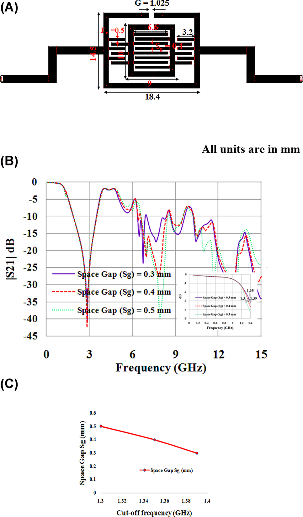
Proposed microstrip design (A) physical outlook (B) frequency simulated responses for different space gaps (C) deviation of cut-off frequency versus space gap.
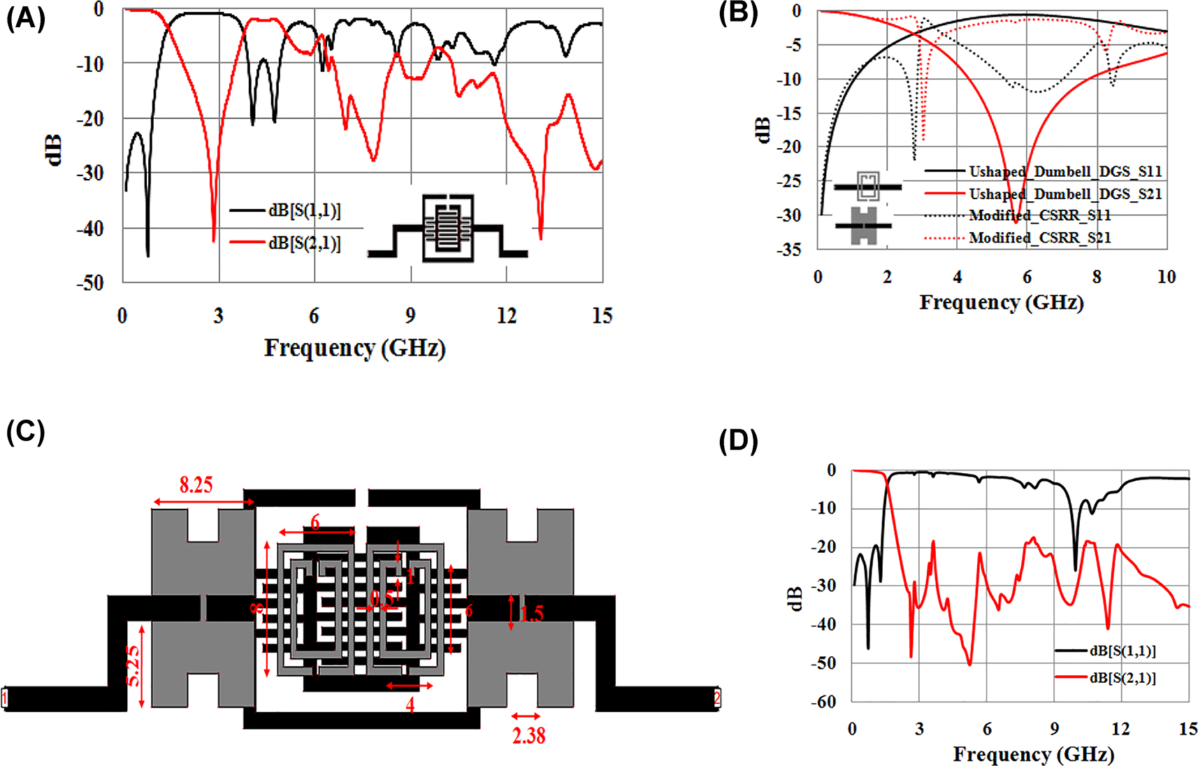
Proposed LPF structure and responses (A) scattering parameters without DGS. (B) Responses of DGS. (C) Complete outlook (grey denotes ground plane & black denotes signal plane) (D) EM simulated frequency responses.
2.1 Filter characteristics
Using some standard Eqs. (1)–(4), the attributes of the proposed LPF can be found. The sharpness of roll-off and is obtained as
where the 40 dB attenuation point is signified by ‘α max’ and the 3 dB attenuation point is denoted by ‘α min’. The 3 dB cut-off frequency is denoted by ‘f c’ and the 40 dB stopband frequency is signified by ‘f s’. A roll-off factor of 43 dB/GHz with −49 dB attenuation at the filter resonant frequency is obtained. The relative stop bandwidth (RSB) of the proposed LPF can be found as
The RSB obtained for the proposed filter is 165%. The size of the filter can be given as
where NCS is normalized circuit size, λ g denotes the guided wavelength at 3 dB cut-off frequency. The NCS of the filter is (0.02 λ g 2 ). The suppression factor is defined as suppression/10 dB which is attained on the basis of average suppression of the stopband and is approximately considered as 2. The figure of merit (FOM) is calculated as
where AF denotes architecture factor or circuit complexity factor and is considered as equivalent to “1” for 2D design. The FOM of the filter is 7095 i.e. the overall index.
2.2 Fabrication and experimental results
The lossy material FR4 is used to fabricate Figure 2C, and the Vector Network Analyser (VNA) N5221A is used to measure the performance of the filter. The experimental and theoretical results of the filter are summarized in Table 1. A wide bandwidth is obtained up to 15 GHz and the average suppression level achieved is almost −20 dB (measured) in harmonic suppression. The proposed LPF has considered the suppression factor (SF) as 2 with sharp selective performance and the return loss (measured) is below −20.3 dB in the whole passband. A good similarity of scattering parameters is observed between the measured and EM simulated results (Figure 3C). Although, due to connector loss, fabrication tolerances, substrate non-uniformity, and other reliabilities, a slight discrepancy can be seen among them. Furthermore, the proposed filter seems to cause some radiation resulting in return losses around 10 GHz for both the simulated and measured results and at 5 GHz in the measured graph. This occurance may be due to some variation in the proper selection of the optimized DGSs dimensions and the relative gaps between different DGSs. However, the reflection losses may cause electromagnetic interference issues in practical applications of the LPF which can be mitigated by fine tuning of the DGSs dimensions. Figure 3A and 3B depicts the photograph of the fabricated LPF structure.
Proposed LPF calculated values.
| Filter characteristics | Measured/EM simulated | Relative stopband width (%) | Insertion loss (dB) | Roll-off ξ (dB/GHz) | Normalised circuit size (λ g 2) | Figure of merit |
|---|---|---|---|---|---|---|
| Calculated values | Measured | 164 | 0.4 | 37 | 0.02 | 6078 |
| EM | 165 | 0.35 | 43 | 0.02 | 7095 |
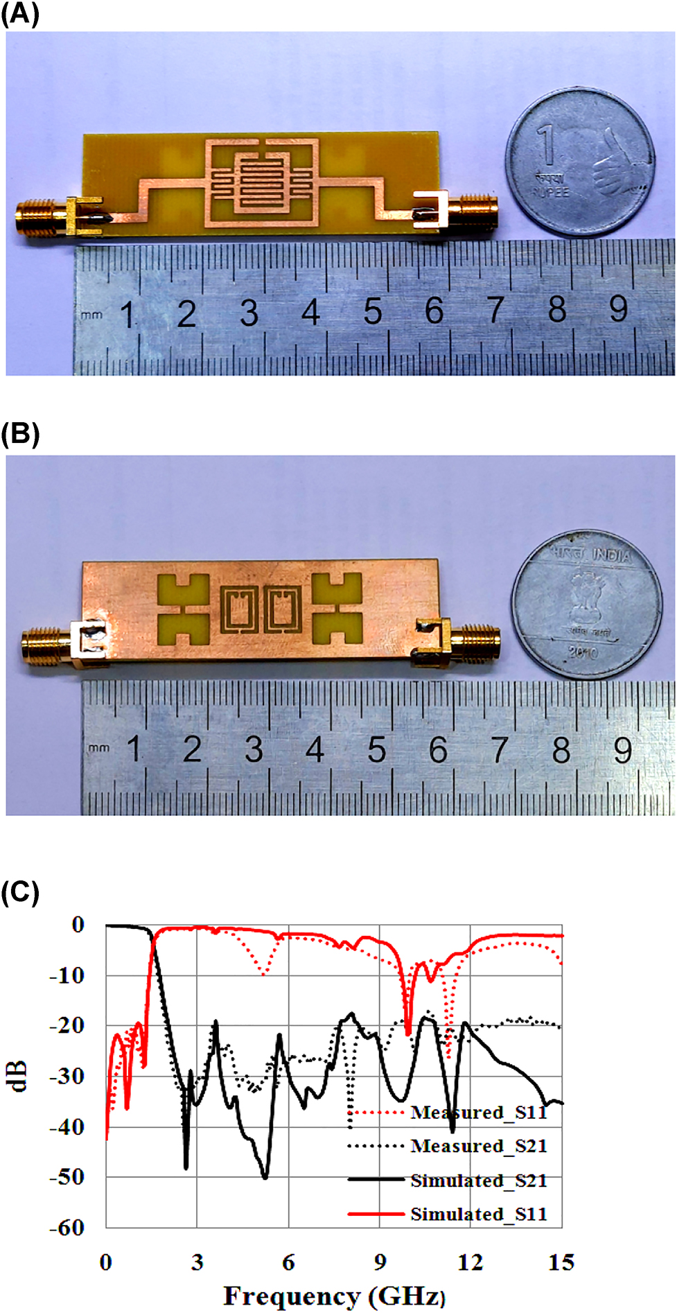
Proposed fabricated LPF (A) view of signal plane (B) view of ground plane (C) measured versus EM frequency simulated result.
2.3 Group delay
The filter order is nearly proportional to group delay (GD) and is defined as the measure of phase distortion. The flattest group delay is intended to produce in the passband region for microwave filters. Although for Chebyshev filters, equi-ripple is exhibited in the passband and for that, group delay is not flat. The standard equation to calculate group delay may be written as
where “ω” is the angular frequency in rad/s which is equal to 2πf and “φ” is the S 21 phase angle. The average group delay in the passband region obtained is 0.3 ns and is depicted in Figure 4.
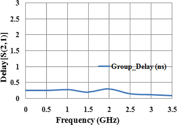
LPF group delay
2.4 Current and electric field distribution
The Zealand IE3D Electromagnetic software is used to examine the vector current distribution at various cut-off frequencies of the proposed LPF and is illustrated in
Figure 5 It is found that the input and output current magnitude is equal at operating frequency 1.5 GHz while its amplitude is diminished at other frequencies. For better understanding, electric field distribution is depicted in Figure 6. At the cut-off frequency (1.5 GHz), the electric field distribution of the proposed LPF is shown for the signal plane (Figure 6A) and ground plane (Figure 6B). At 1.5 GHz, the strong electrical coupling is produced between the IDCs and hence maximum field is confined on it.
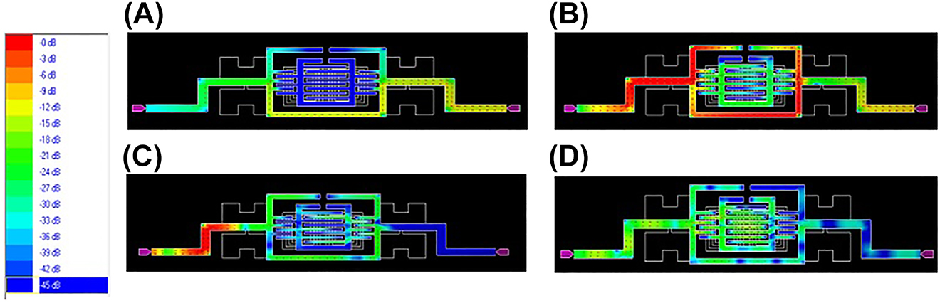
LPF current distribution at (A) 0.7 GHz, (B) 1.5 GHz, (C) 5 GHz, (D) 11 GHz.
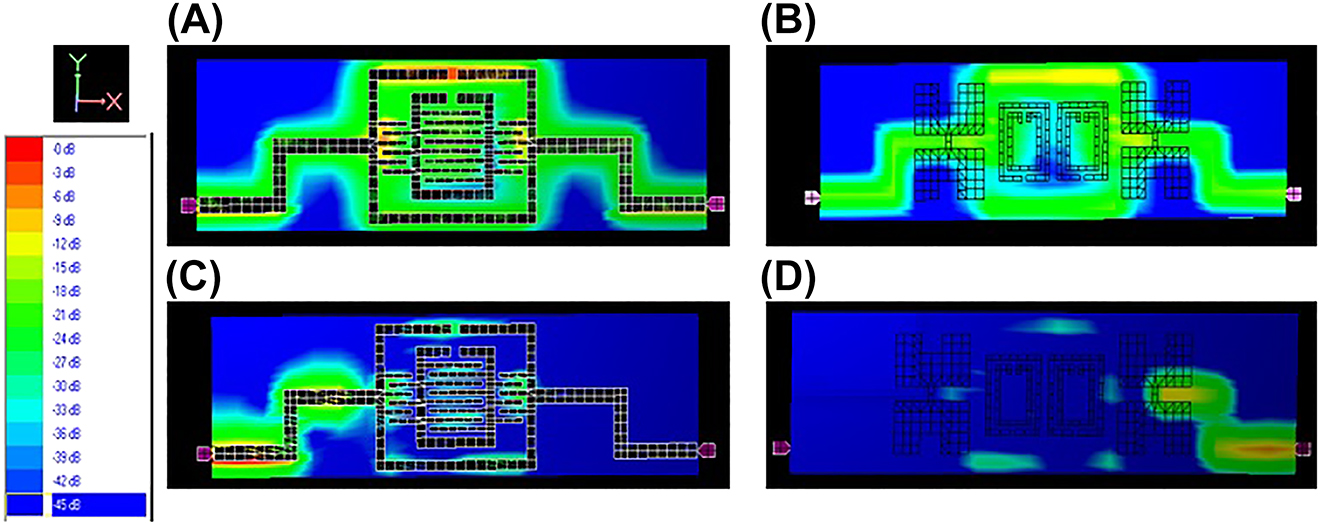
LPF (A) electric field distribution at 1.5 GHz for signal plane (B) electric field distribution at 1.5 GHz for ground plane (C) electric field distribution at 5 GHz for signal plane (D) electric field distribution at 5 GHz for ground plane.
3 Equivalent circuit of the proposed LPF
The exact equivalent circuit of the proposed LPF can be obtained by using Cauer’s T-network [31]. The introduced LC circuit of the proposed filter is extracted from the structure (Figure 7A) and the circuit modeling is performed using Advanced Design System (ADS) software. The equivalent circuit model presents the tank circuit L 1, C 1 for the interdigital capacitors and L 2 for the line inductance of the high impedance transmission line. The small capacitance C 2 denotes the gap (G) of the ORs. The tank circuit L 3, C 3 is generated due to the patch and gap present in the modified CSRR cell. C c is the coupling capacitance between the interdigital capacitor and modified CSRR. Similarly, the tank circuit L g, C g represents the DGSs etched in the ground plane of the microstrip structure. The step discontinuity region on the metallic ground plane possesses large fringing fields, which include parasitic capacitance Cp in the equivalent circuit. The C p presents the parasitic capacitance between the interdigital capacitor and ground plane. The characteristics impedance of the microstrip line may change due to the presence of C p.
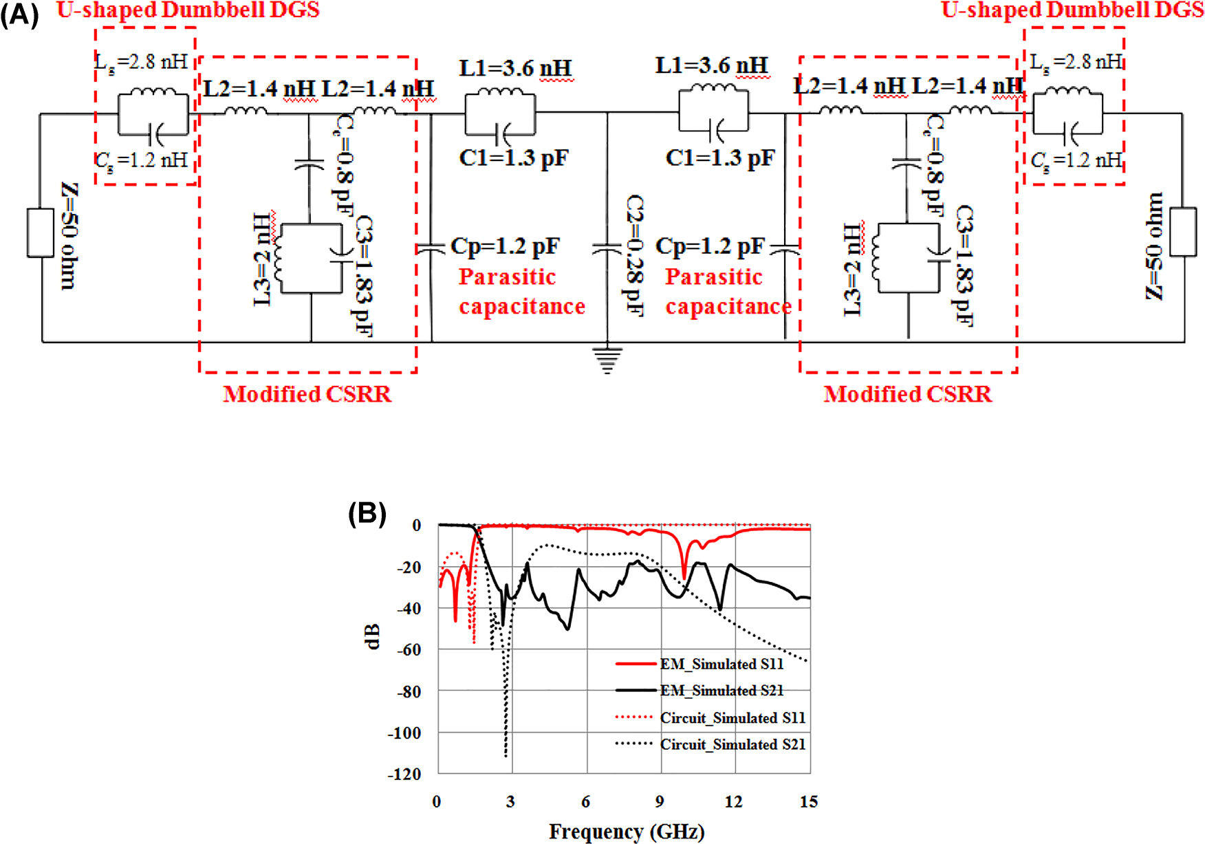
Proposed LPF (A) lumped equivalent circuit (B) circuit versus electromagnetic simulated result.
The generalized equation to calculate each interdigital capacitor capacitance can be found as [32]
Where, ‘n’ represents the number of fingers and ‘l’ denotes the length of interdigital arms. In the proposed structure, ‘n’ is even and the value of the capacitance ‘C’ increases or decreases depending on ‘n’ of the interdigital capacitor.
For the DGSs in the existing structure, inductance and capacitance is generated and can be calculated as [32]
where “f o” is the resonating frequency and the 3 dB cut-off frequency of a DGS unit cell is denoted by “f c”. The 50 Ω characteristic impedance (Z o) of the microstrip transmission line can be calculated as [32]
And the effective dielectric constant is given by,
(W/h) provides the width and height ratio of the transmission line and (ϵ r) denotes the relative dielectric constant.
The per unit length inductance (L pul) and capacitance (C pul) of the modified CSRR can be given as [33]:
where, q denotes the length of the outer ring of modified CSRR by not considering the strip thickness present on either side of the ring, and p denotes the width of the outer ring. L c and C c are the intrinsic inductance and capacitance of the modified CSRR unit cell respectively.
The circuit simulated and electromagnetic simulated responses are compared (Figure 7B). The circuit simulated graph provides a cut-off at 1.62 GHz with very low insertion loss 0.15 dB, and RSB 161%. Since the accurate values of the lumped elements are difficult to extract, some mismatches arises between the circuit simulated and EM simulated results. Moreover, this deviation occurs may be due to connector loss and substrate imperfection.
The performance comparison of the newly proposed work with previous related LPFs is done accordingly in Table 2. The structure in [8, 10] has the smallest circuit size of all the filters in the table, but it has poor roll-off characteristics. Similarly [22, 34], [35], [36], have very low insertion loss despite poor FOM [22]. has a good band suppression level in contempt of large insertion loss and narrow stopband band performance as compared with the proposed design. Furthermore, the proposed LPF is fabricated on low-cost FR4 substrate but; costlier substrate is used for the other works except [19]. This provides the proposed design an additional advantage. Hence as per Table 2, the proposed filter is economical having wide attenuation band and large RSB.
Performance comparison study.
| References | Substrate used | fc (GHz) | Insertion loss in PB (dB) | ξ (dB/GHz) | Relative stopband width | Band suppression level and attenuation band | Normalized circuit size (
|
Figure of merit |
|---|---|---|---|---|---|---|---|---|
| [8] | Roger RO4350 | 1.2 | NA | 17 | 1.58 | −15 dB up to 10.35 GHz | 0.009 | 4242 |
| [10] | Rogers RO4350 | 1.6 | 0.5 | 33 | 1.52 | −10 dB up to 12 GHz | 0.006 | 8360 |
| [19] | FR4 | 2.4 | 0.35 | 36 | 0.86 | −20 dB up to 6 GHz | 0.07 | 885 |
| [22] | Roger RO 4003 | 2.4 | 0.8 | 37.2 | 1.62 | −30 dB up to 9.8 GHz | 0.0378 | 3189 |
| [34] | RO4003 | 2.85 | 0.3 | 7.17 | 1.32 | −20 dB up to 6.3 GHz | 0.046 | 235 |
| [35] | Roger | |||||||
| RO4003 | 5.2 | 0.3 | 29 | 0.91 | −20 dB up to 14 GHz | 0.466 | 114 | |
| [36] | RO4003 | 3 | 0.3 | 34 | 1.17 | −20 dB up to 11.5 GHz | 0.13 | 612 |
| Proposed work | FR4 | 1.5 | 0.35 | 43 | 1.65 | −20 dB up to 15 GHz | 0.02 | 7095 |
4 Conclusions
In this paper, a compact (0.14 λg × 0.18 λg), sharp rejection characteristics (43 dB/GHz), low insertion loss (0.35 dB), wide attenuation band 1.5 GHz LPF is proposed for applications in global positioning system (1.5 GHz), telecommunications (1.6 GHz), and audio broadcasting (1.4 GHz). The rectangular-shaped ORs are loaded with interdigital capacitor units for the proposed LPF design. The two dissimilar shapes of DGSs are introduced to suppress the higher spurious harmonics for widened stopband characteristics. The equivalent lumped circuit of the proposed filter is derived, fabricated, and finally measured for validation.
Acknowledgments
The authors are thankful to ISRO project on “Applicability of Electromagnetic Metamaterials in Antennas and Microwave Circuits for use in Space Applications” and Mr. Dipesh Debnath, Lab technician, National Institute of Technology, Agartala and for their support.
-
Author contributions: All the authors have accepted responsibility for the entire content of this submitted manuscript and approved submission.
-
Research funding: None declared.
-
Conflict of interest statement: The authors declare no conflicts of interest regarding this article.
References
[1] R. T. Hammed, S. H. Hassan, and S. L. Ajeel, “New compact low-pass filter (LPF) using cascaded square open loop resonator,” AEU Int. J. Electron. Commun., vol. 92, pp. 93–97, 2018, https://doi.org/10.1016/J.AEUE.2018.05.030.Search in Google Scholar
[2] B. Hiedari and F. Shama, “A harmonics suppressed microstrip cell for integrated applications,” AEU Int. J. Electron. Commun, vol. 83, pp. 519–522, 2018, https://doi.org/10.1016/j.aeue.2017.11.009.Search in Google Scholar
[3] L. Ge, J. Wang, and Y. Guo, “Compact microstrip lowpass filter with ultra-wide stopband,” Electron. Lett., vol. 46, no. 10, pp. 689–691, 2010, https://doi.org/10.1049/el.2010.0357.Search in Google Scholar
[4] M. Hayati, M. Najafi, F. Shama, and S. Zarghami, “Microstrip lowpass filter with ultra-wide stopband using folded structures,” Frequenz, vol. 73, nos. 5–6, pp. 1–8, 2019, https://doi.org/10.1515/freq-2018-0237.Search in Google Scholar
[5] J. L. W. Li, S. W. Qu, and Q. Xue, “Compact microstrip lowpass filter with sharp roll-off and wide stop-band,” Electron. Lett., vol. 45, no. 2, pp. 110–111, 2009, https://doi.org/10.1049/el:20093246.10.1049/el:20093246Search in Google Scholar
[6] L. Li, Z. F. Li, and Q. F. Wei, “Compact and selective lowpass filter with very wide stopband using tapered compact microstrip resonant cells,” Electron. Lett., vol. 45, no. 5, pp. 267–268, 2009, https://doi.org/10.1049/el:20092120.10.1049/el:20092120Search in Google Scholar
[7] S. S. Karthikeyan and R. S. Kshetrimayum, “Compact and wide stopband lowpass filter using open complementary split ring resonator and defected ground structure,” Radio Engg, vol. 24, no. 3, pp. 708–3711, 2015, https://doi.org/10.13164/re.2015.0708.Search in Google Scholar
[8] X. Chen, L. Zhang, Y. Peng, Y. Leng, H. Lu, and Z. Zheng, “Compact lowpass filter with wide stopband bandwidth,” Microw. Opt. Technol. Lett., vol. 57, no. 2, pp. 367–371, 2015, https://doi.org/10.1002/mop.28853.Search in Google Scholar
[9] Z. Du, H. Yang, H. Zhang, and M. Zhu, “Compact lowpass filter with high suppression level and wide stop- band using stepped impedance m-shape units,” Microw. Opt. Technol. Lett., vol. 56, no. 12, pp. 2947–2950, 2014, https://doi.org/10.1002/mop.28744.Search in Google Scholar
[10] X. B. Wei, P. Wang, M. Q. Liu, and Y. Shi, “Compact wide-stopband lowpass filter using stepped impedance hairpin resonator with radial stubs,” Electron. Lett., vol. 47, no. 15, pp. 862–863, 2011, https://doi.org/10.1049/el.2011.1414.Search in Google Scholar
[11] M. Hayati, H. Kakaee, A. Fard, and M. Nosrati, “A novel miniaturized wide-band elliptic function low-pass filter using microstrip open-loop and semi-hairpin resonators,” Prog. In Electromagnetics Research C, vol. 10, pp. 243–251, 2009, https://doi.org/10.2528/pierc09082608.Search in Google Scholar
[12] L. Zhu and K. Wu, “Accurate circuit model of interdigital capacitor and its application to design of New quasilumped miniaturized filters with suppression of harmonic resonance,” IEEE Trans. Microw. Theor. Tech., vol. 48, no. 3, pp. 347–356, 2000, https://doi.org/10.1109/22.826833.Search in Google Scholar
[13] G. D. Alley, “Interdigital capacitors and their application to lumped element microwave integrated circuits,” IEEE Trans. Microw. Theor. Tech., vol. 18, no. 12, pp. 1028–1033, 1970, https://doi.org/10.1109/tmtt.1970.1127407.Search in Google Scholar
[14] R. K. Maharjan, B. Shrestha, and N. Y. Kim, “Microstrip cross-coupled interdigital SIR based bandpass filter,” Radio Eng, vol. 21, no. 3, pp. 881–885, 2012.Search in Google Scholar
[15] M. Kazemi, S. Lotfi, H. Siahkamari, and M. Mohammadpanah, “UWB bandpass filter with ultra-wide stopband based on ring resonator,” Frequenz, vol. 72, nos. 5–6, pp. 1–8, 2017, https://doi.org/10.1515/freq-2016-0312.Search in Google Scholar
[16] A. Mohamadinia, F. Shama, and M. A. Sattari, “Miniaturized bandpass filter using coupled lines for wireless applications,” Frequenz, vol. 78, pp. 7–8, 2021. https://doi.org/10.1515/freq-2020-0129.Search in Google Scholar
[17] D. Singhal, S. Singh, V. Kaushal, A. Birwal, and K. Patel, “Wide band stop response using interdigital capacitor/CSRR DGS in elliptical microstrip low-pass filter,” Jour. of Microw., Optoelectro. and Electromag. Applic., vol. 19, no. 4, pp. 495–509, 2020, https://doi.org/10.1590/2179-10742020v19i4945.Search in Google Scholar
[18] M. Bod and A. R. Mallahzadeh, “Band-pass filter design using modified CSRR-DGS,” Int. J. RF Microw. Computer-Aided Eng., vol. 24, no. 5, pp. 1–5, 2013, https://doi.org/10.1002/mmce.20797.Search in Google Scholar
[19] S. Sen, T. Moyra, and D. Sarkar, “Modelling and validation of microwave LPF using modified rectangular split ring resonators (SRR) and defected structures,” AEU Int. J. Electron. Commun, vol. 88, pp. 1–10, 2018, https://doi.org/10.1016/j.aeue.2018.02.009.Search in Google Scholar
[20] M. A. Sharkawy, A. Boutejdar, and E. Galal, “Design of Ultra-Wide Stop-Band dgs low-pass filter using meander and multilayer techniques,” Microw. Opt. Technol. Lett., vol. 55, no. 6, pp. 1276–1281, 2013, https://doi.org/10.1002/mop.27541.Search in Google Scholar
[21] A. Mandal, S. Sen, and T. Moyra, “Design of coplanar waveguide LPFs using open stub and defected ground structure (DGS),” Proc. of International Conf. on Computa. Intelligence & IoT (ICCIIoT), vol. 2, no. 3, pp. 657–661, 2018.Search in Google Scholar
[22] L. F. Shi, Z. Y. Fan, and D. J. Xin, “Miniaturized low-pass filter based on defected ground structure and compensated microstrip line,” Microw. Opt. Technol. Lett., vol. 62, no. 3, pp. 1093–31097, 2019, https://doi.org/10.1002/mop.32144.Search in Google Scholar
[23] T. K. Rekhaa, P. Abdullaa, P. M. Jasmine, and A. R. Anua, “Compact Microstrip low- pass filter with high harmonics suppression using defected structures,” AEU Int. J. Electron. Commun., vol. 115, p. 153032, 2020, https://doi.org/10.1016/j.aeue.2019.153032.Search in Google Scholar
[24] M. Kumar, S. N. Islam, G. Sen, S. K. Parui, and S. Das, “Harmonic suppressed wilkinson power divider with filtering characteristic for GSM application,” in IEEE MTT-S International Microwave and RF Conference (IMaRC), Kolkata, India, IEEE, 2018, p. 19079296.10.1109/IMaRC.2018.8877333Search in Google Scholar
[25] A. Mandal and T. Moyra, “Stepped impedance hairpin resonator (SIHR) based compact lowpass filter with wide attenuation band,” Electromagnetics, vol. 42, no. 1, 2022, https://doi.org/10.1080/02726343.2022.2061822.Search in Google Scholar
[26] A. K. Panda, M. Pattnaik, and R. Swain, “CSRR embedded CPW band-stop filter,” IETE J. Res., p. 1684847, 2019, https://doi.org/10.1080/03772063.Search in Google Scholar
[27] D. K. Choudhary and R. K. Chaudhary, “Compact lowpass and dual-band bandpass filter with controllable transmission zero/center frequencies/passband bandwidth,” IEEE Transactions on Circuits and Systems II: Express Briefs, vol. 67, no. 6, pp. 1044–1048, 2020, https://doi.org/10.1109/tcsii.2019.2931446.Search in Google Scholar
[28] D. K. Choudhary and R. K. Chaudhary, “Miniaturized quad band filter with improved selectivity using split ring resonators and metallic strips,” International Jour. of RF and Microw. Computer-Aided Engg., vol. 31, no. 10, pp. 1–9, 2021. https://doi.org/10.1002/mmce.22809.Search in Google Scholar
[29] A. Mandal and T. Moyra, “Designing and validation of miniaturized CPW based microwave notch Filter using loaded modified multiple split ring resonator (MSRR),” IETE J. Res., p. 1962417, 2021, https://doi.org/10.1080/03772063.Search in Google Scholar
[30] T. Moyra, S. K. Parui, and S. Das, “Design and development of lowpass filter and harmonics reduction,” Int. Jour. on Elec. Engg. and Informatics, vol. 3, no. 3, pp. 336–349, 2011, https://doi.org/10.15676/ijeei.2011.3.3.6.Search in Google Scholar
[31] S. K. Parui and S. Das, “An asymmetric defected ground structure with elliptical response and its application as a lowpass filter,” AEU Int. J. Electron. Commun, vol. 63, pp. 483–490, 2009, https://doi.org/10.1016/j.aeue.2008.04.002.Search in Google Scholar
[32] J. S. Hong and M. J. Lancaster, Microstrip Filters for RF/Microwave Applications, New York, John Wiley & Sons, Inc, 2001, pp. 157–158.10.1002/0471221619Search in Google Scholar
[33] D. Sarkar and T. Moyra, “An improved parametric analysis of CSRR loaded with microstrip line for ultra wide band frequency range,” Microw. Opt. Technol. Lett., vol. 59, no. 3, pp. 661–664, 2017, https://doi.org/10.1002/mop.30370.Search in Google Scholar
[34] W. A. E. Ali and A. Boutejdar, “Design of low-pass filter using meander inductor and U-form hi-lo topology with high compactness factor for L-band Applications,” Prog In Electromag. Research, vol. 55, pp. 95–107, 2017, https://doi.org/10.2528/pierm17013103.Search in Google Scholar
[35] L. Wang, H. C. Yang, and Y. Li, “Design of compact microstrip low-pass filter with ultra-wide stopband using sirs,” Prog. In Electromag. Resea. Lett., vol. 18, pp. 179–186, 2010, https://doi.org/10.2528/pierl10091201.Search in Google Scholar
[36] A. Boutejdar, M. Challal, and S. E. Hani, “Design of new broad stop band (BSB) lowpass filter using compensated capacitor and Π-H-Π DGS resonator for radar applications,” Prog. In Electromag. Resea. M, vol. 73, pp. 91–100, 2018.10.2528/PIERM18062605Search in Google Scholar
© 2022 Walter de Gruyter GmbH, Berlin/Boston
Articles in the same Issue
- Frontmatter
- Research Articles
- Compact low-pass filter (LPF) with wide harmonic suppression using interdigital capacitor
- Design and analysis of a multiple notched UWB-BPF based on microstrip-to-CPW transition
- A compact S-band band-pass filter with ultra-wide stopband
- Design and fabrication of an ultra compact Gysel power divider with harmonic suppression by using U shaped resonators
- A high angle stable and polarization symmetric dual band reconfigurable frequency selective surface
- Characterization of dual-band circularly polarized mushroom-shaped monopole antenna with modified ground plane
- Novel multilayer antenna array with metamaterial structures for 5G applications
- Compact quadband two-port antenna with metamaterial cell-inspired decoupling parasitic element for mobile wireless applications
- Gain enhancement of a SIW H-plane horn antenna using of metamaterial array
- Optimized SIW antipodal Vivaldi antenna array using Fourier series equations for C-band applications
- Design and performance analysis of a compact, wideband dual polarized antenna for WLAN & WiMAX applications
- Miniaturised ultra-wideband rectangular shaped slot antenna for ground penetrating radar applications
- Performance analysis and rain attenuation modelling of RoFSO link for hilly region of India