
Peristaltic thrusting of a thermal-viscosity nanofluid through a resilient vertical pipe
-
Ramzy M. Abumandour
 ,
Islam M. Eldesoky
,
Islam M. Eldesoky


Abstract
In the article, the effects of the thermal viscosity and magnetohydrodynamic on the peristalsis of nanofluid are analyzed. The dominant neutralization is deduced through long wavelength approximation. The analytical solution of velocity and temperature is extracted by using steady perturbation. The pressure gradient and friction forces are obtained. Numerical results are calculated and contrasted with the debated theoretical results. These results are calculated for various values of Hartmann number, variable viscosity parameter and amplitude ratio. It is observed that the pressure gradient is reduced with an increase in the thermal viscosity parameter and that the Hartmann number enhances the pressure difference.
1 Introduction
Many researches deal with the fluid viscosity as a constant value for the sake of simplicity. This assumption is not accepted in real life situations. Thus, the effect of temperature and pressure on the coefficient of viscosity for actual fluids must be taken into consideration. The mutation in viscosity due to thermal change is large for abundant liquids such as water, oils, and blood. Viscosity variance is usually very small because of the pressure difference, thus it can be neglected [1], [2]. Actually, there is a non-uniform thermal distribution in many thermal transport operations. When there is a large thermal gradient in the system, the fluid viscosity may obviously change. Therefore, the influence of temperature on viscosity in thermal transport processes should be studied [3], [4], [5], [6], [7].
The variable-viscosity models are important along with peristalsis and thermal viscosity that has serious important characteristics in certain physiological and industrial materials. Peristalsis of power-law fluids with variable consistency was presented by Shukla and Gupta [8]. It was noticed that when the pressure drops, flow rate gets high for most of the peristaltic wave due to the enhancement in the pseudo-plasticity of the fluid. Furthermore, it was noticed that the wall friction gets diminished as the uniformity rebated. El Shamy et al. [9] analyzed the effect of thermal viscosity and an incorporated endoscopy on peristalsis by using perturbation expansions. It was noticed that with raising viscosity, the pressure rise is diminished while it gets promoted with growing the wave number and amplitude ratio.
For a non-uniform tube, the effect of peristalsis and thermal viscosity was analyzed by Srivastava et al. [10]. It was noticed that for a null flow rate, the pressure difference is reduced with a decrease in the fluid viscosity, but at a definite flow rate, the pressure rise is independent of the viscosity variation. It was also found that beyond this critical flow rate, raising the viscosity implies to an increase in the pressure difference. More investigations of thermal viscosity with peristalsis took place such the one done by Khan et al. [11] for diagonal pumping of non-Newtonian fluids.
The interaction between the thermal effect and peristalsis is widely used in many applications through the consideration of the sensitivity of thermal viscosity [12], [13]. The effect of magnetohydrodynamics and wall properties on the peristaltic transport of a Jeffrey nanofluid in channel was studied [14]. The authors investigated the analytical solutions for the stream function and the temperature. For both Jeffrey and Newtonian fluids, the effects of some important parameters were investigated on the physical quantities of the flow through the graphs. It was found that for the Jeffrey fluid, the flow rate and thermal effect are lower than that of the Newtonian fluid. It was found that the higher the values of the nanoparticle concentration, the lower the values of the velocity and temperature.
The combination between the electrical conductivity of the nanoparticles and the conventional base fluid through the effect of magnetic force with heat transfer over convectively heated surfaces is important in many engineering and industrial applications [15], [16], [17], [18], [19]. Magnetohydrodynamics represent those phenomena where in an electrically conducting fluid, the electric current density (Ι) in the moving conductive fluid can be produced by a magnetic field. Thus, the flow is considered to be axisymmetric and a uniform magnetic field is applied in the transverse direction to the flow [20], [21], [22], [23], [24]. The non-dimensional problem is formulated in the wave frame under the long wavelength and low Reynolds number approximations. For a non-uniform porous channel, the effect of elasticity, nanoparticle concentration, and Joule heating on the peristalsis of flow have been presented and compared with those of a uniform channel [25]. Results were presented for the flows through uniform and non-uniform models with various parameters. For the uniform channel, the fluid velocity was shown to be lower than that of the diverging channel. It was observed that for the uniform channel, fluid velocity is higher than that of the non-uniform channel.
Because of the enormous implementations in medicine and engineering, nanofluid motion through channels/tubes has attracted appreciable attention. For the sake of improvement of the thermal physical properties of fluids, nanoparticles are suspended in these fluids. Various materials are used in order to form nanoparticles, such as metals (Au, Ag, Fe, Al, Cu), nitride ceramics (SiN, AlN), carbide ceramics (SiC, tiC), oxide ceramics (CuO, Al2O3, TiO2), and carbon nanotubes and semiconductors. Recently, nanoparticle core–polymer shell composites and alloyed nanoparticles are used as nanoparticles. Most solids have a great thermophysical properties compared with conventional thermal effect of fluids such as water, oil, and ethylene glycol. The viscosity, thermal conductivity, thermal diffusivity, and convective heat transfer coefficients of these fluids are improved by its nanoparticles [26], [27], [28], [29], [30], [31]. The influence of nanoparticles on peristalsis in presence of magnetohydrodynamics has been analyzed [32]. It was noticed that, energy, nanoparticle concentration, porosity and Grashof number (Gr) enhance the flow rate and thermal effect at the centerline of the cross-sectional area and decrease near the channel wall. The pressure gradient was noticed to decrease with increasing the Gr, energy, nanoparticle concentration, and porosity. Ferromagnetic nanofluid investigation for peristalsis in an elastic tube was illustrated by Akbar and Butt [33]. It was found that the variation in pressure gradient was due to the change in the Hartmann number. Also, it was found that the pressure gradient decreases with an increase in the Hartmann number, Darcy number, and Gr. It was observed that for pure water that the pressure gradient is lower than that of Cu–water. The electromagnetic forces enhance the velocity unlike the buoyancy forces. The thermal effect of pure water also was seen to be enhanced than that of Cu–water. Generally, there are many applications of nanofluids that encourage towards studying them, some of which, medicine (cancer medication, safer surgery by cooling, magnetic drug targeting); nanofluid coolant (electronics, vehicle and transformer); chemicals and materials and industry (textiles and printing, food and drink, oil and gas).
2 Mathematical formulation
Consider a nanofluid axisymmetric flow in a regular cylindrical pipe of radius Ro. The pipe wall is malleable upon which are enjoined sinusoidal peristaltic waves of limited amplitude traveling down its edge. The frame of the wall artery can be depicted as (See Figure 1):
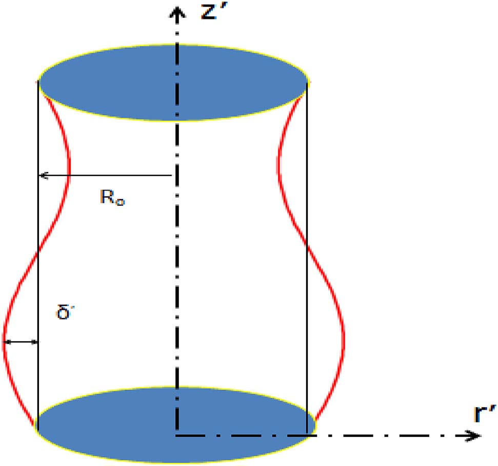
Problem form.
2.1 Mass equation
2.2 Axial momentum
2.3 Radial momentum
The energy equation can be expressed as [27]:
The boundary conditions of nanofluid on the wall can be written as:
Introducing the following dimensionless variables
3 Solution method
Using the long wavelength approximation
3.1 Reduced radial momentum equation
3.2 Reduced axial momentum equation
3.3 Reduced energy equation
3.4 The non-dimensional slip velocity and temperature conditions are
where
The expression for the temperature distribution (θ) can be extracted from the solution of Equation (12) subject to boundary conditions Equations (15) and (16) as follows
The expression for the velocity distribution (w) can be calculated as the solution of Equation (11) subject to boundary conditions Equations (13) and (14) as follows
The volumetric flow rate can be obtained from the relation
Thus, we can write down the pressure difference with the axial coordinates as
The stream function can be obtained from the relation of the velocity as
The expression of wall shear stress is computed as
where
4 Results and discussions
Validation of the problem
The theoretical solution and results for this analysis have been compared with Bintul Huda et al. [35]. In this study, the volumetric flow rate has been considered in Equation (23), however, Equation (24) was used in [35]. This variation affects the pressure gradient, flow rate and temperature.
Velocity profiles for different solid with water at (Q = 0.5525, S = 2, Gr = 2, α = 0.3, δ = 0.1, φ = 0.004)
Mathematical results
Figures 2 and 3 represent the mean velocity distribution w(r) with variations in nanoparticle concentration (φ) and heat source parameter (S). Significant elevation in mean velocity is obtained with decreasing the nanoparticle concentration (φ), as seen in Figure 2, where nanofluid is found to be harmonious to the lowest flow rate in comparison with pure fluid. Results present symmetric velocity variations through the tube cross-sectional area of the artery. This modality of attitude is promoted by enhancing the thermal effect (S) as seen in Figure 3. Maximum velocity is obtained for pure fluid while the minimum velocity is linked with nanofluids that successfully minimize flow rate.
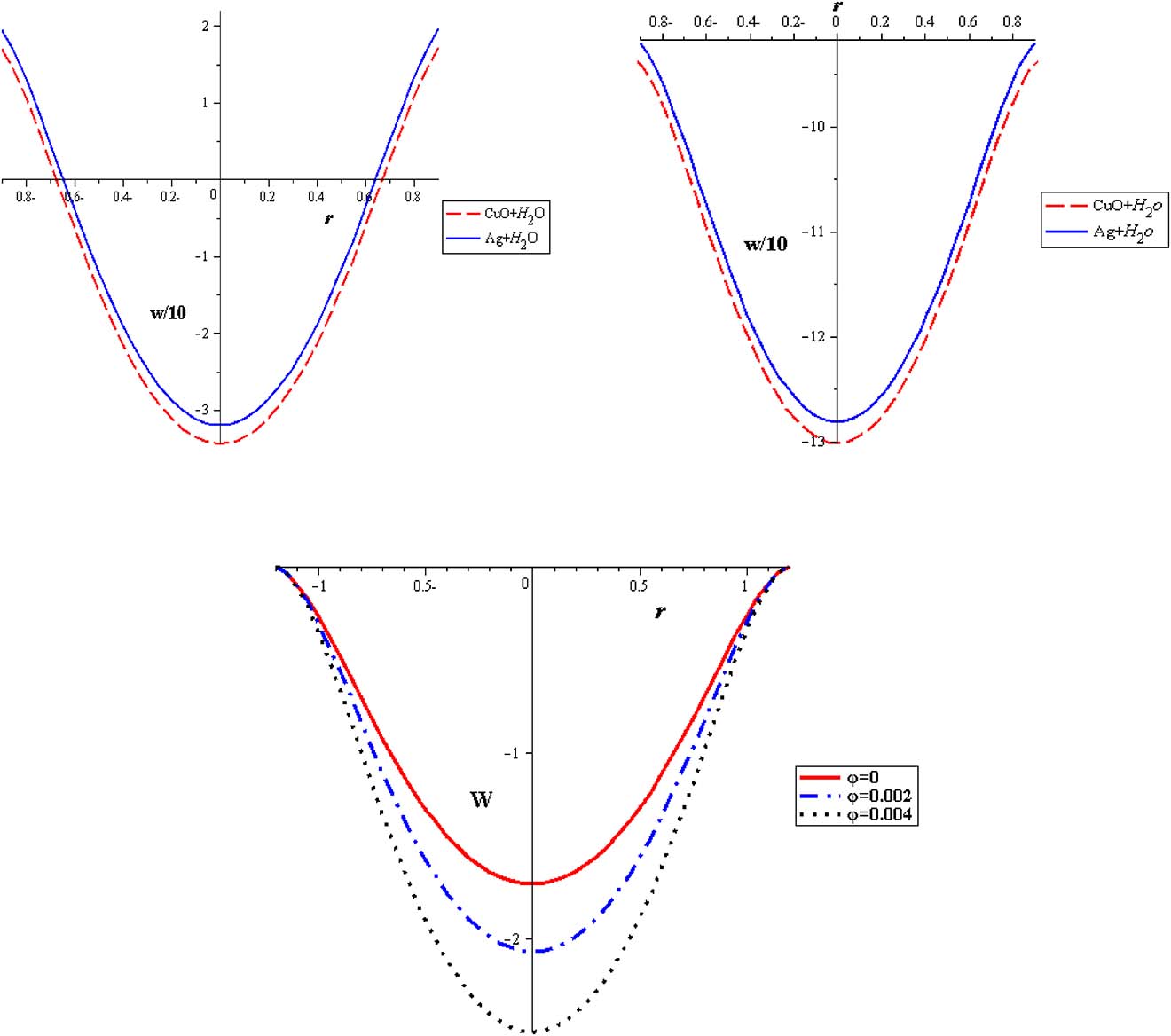
Velocity profiles with different nanoparticles concentration at (Q = 0.1, S = 2, Gr = 2, α = 0.3, δ = 0.2).
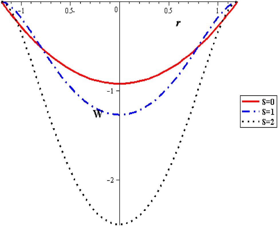
Velocity profiles with different heat source at (Q = 0.1, Gr = 2, α = 0.3, δ = 0.2, φ = 0.004).
The distribution of velocity with the flow rate is analyzed in Figure 4 where an increase in the mean flow rate reduces the flow velocity. Figure 5 is shows that the gravitational force reduces the flow velocity. When the temperature is applied on the velocity profile, the velocity of the flow is decreased with an increase in the viscosity (α), as seen in Figures 6 and 7.
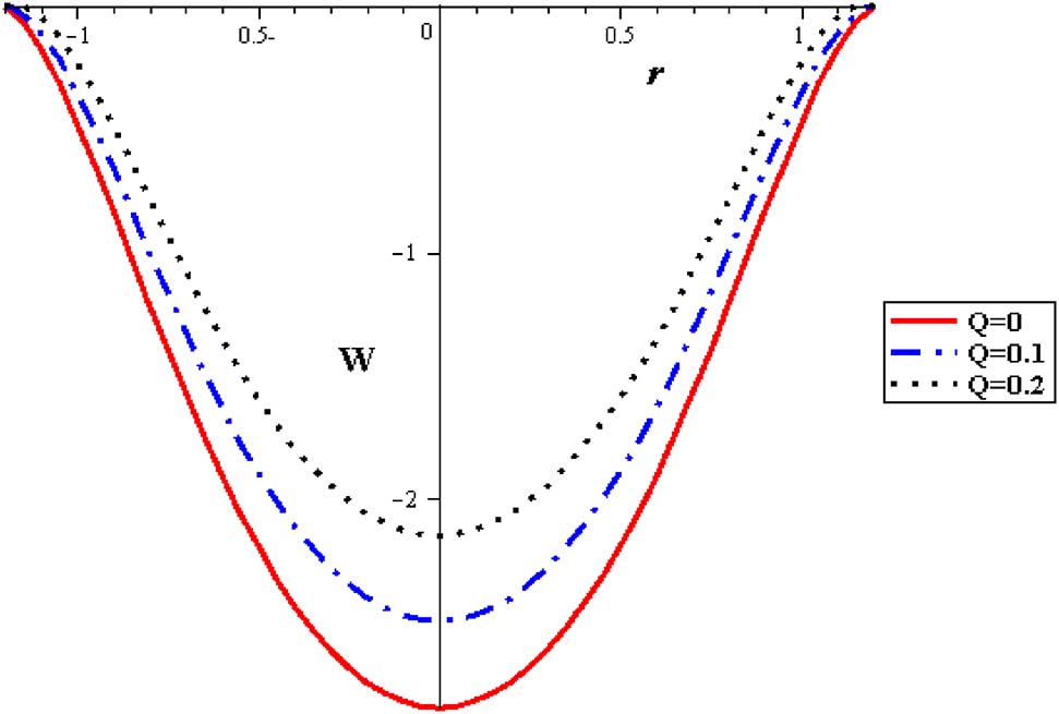
Velocity profiles with different flow rate at (φ = 0.004, S = 2, Gr = 2, α = 0.3, δ = 0.2).
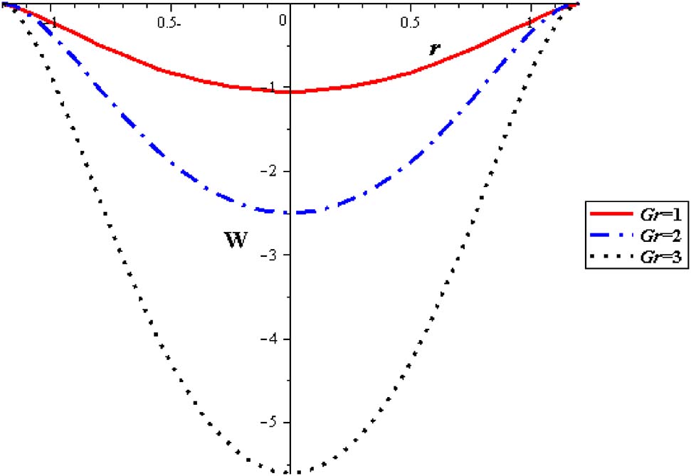
Velocity profiles with different Gr at (Q = 0.1, φ = 0.004, S = 2, α = 0.3, δ = 0.2).

Velocity profiles with different α at (Q = 0.1, φ = 0.004, S = 2, δ = 0.2, Gr = 2).
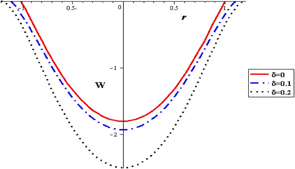
Velocity profiles with different δ at (Q = 0.1, φ = 0.004, S = 2, α = 0.3, Gr = 2).
The thermal distributions with different nanoparticle concentration are signified in Figure 8, where nanofluid attains the lowest temperatures compared to pure fluid. With increasing nanoparticle concentration (φ), the demand influence of cooling the pumping fluid is accomplished. Subsequently, for thermal patterns in peristalsis of nanofluid pumping, the preferable cooling execution is related with nanofluids. In results, through the uniform cross-sectional pipe, parabolical variations are noticed and extreme temperature permanently occur at the pipe axis of symmetry. Considerable thermal increase is obtained with raising the heat absorption (S) as seen in Figure 9. The highest temperature is acquired without nanoparticles where the lowest temperatures are connected with nanofluid. The peristaltic motion of the artery reduces the flow temperature, Figure 10.
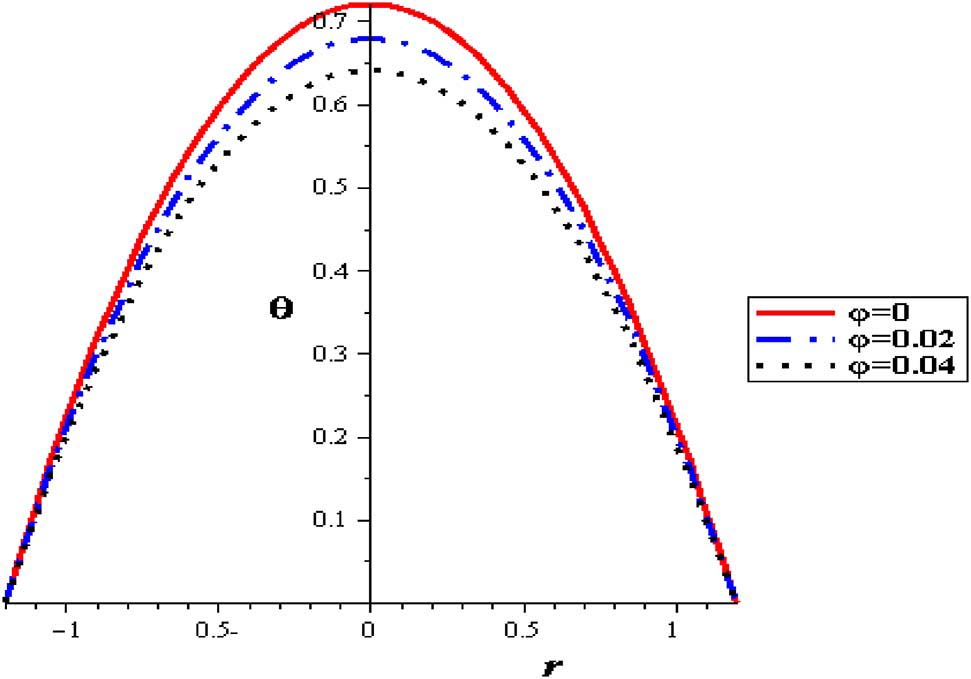
Temperature profiles with different nanoparticles concentration at (δ = 0.2, S = 2).
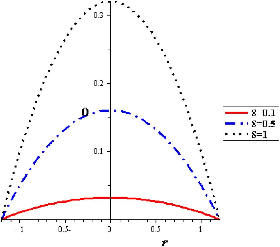
Temperature profiles with different source heat at (φ = 0.04, δ = 0.2).
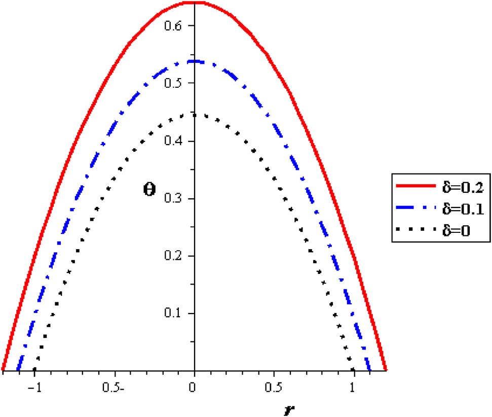
Temperature profiles with different δ at (φ = 0.04, S = 2).
Figures 11–15 show premeditation into the restraint in pressure gradient (ΔP) with different locations (z), thermal variable (S), nanoparticle concentration (φ), variable viscosity parameter (α) and Gr. Pressure difference diminishes with a growing the thermal energy (S) and the variable viscosity parameter (α). Linear relationship between the pressure difference and the mean flow rate (ΔP, Q) through various parameters has been noticed. For higher values of thermal source (S), the pressure difference rises at the range of flow rate, i. e. (1 < Q < 2). Pressure difference is improved with Gr and nanoparticle concentration (φ).
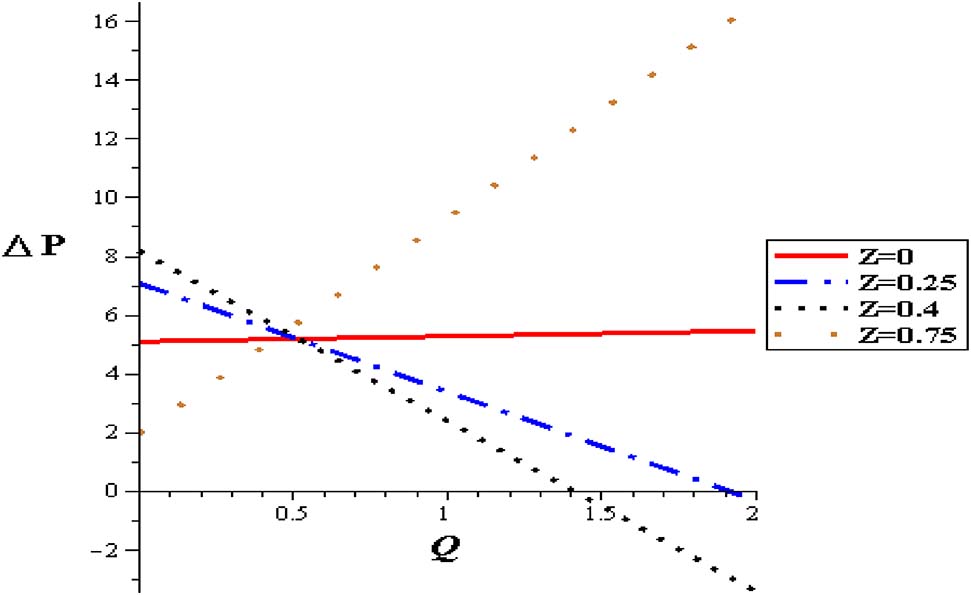
Pressure flow rate profiles with different positions at (Gr = 2, φ = 0.004, α = 0.3, S = 2, δ = 0.1).
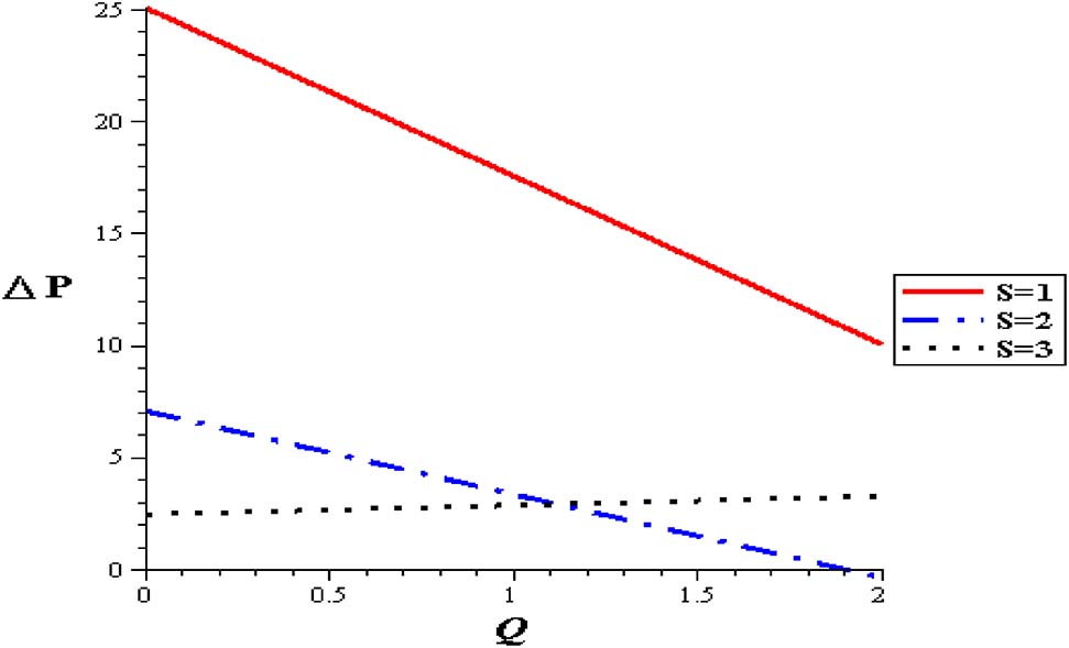
Pressure flow rate profiles with different heat source at (Gr = 2, φ = 0.004, α = 0.3, δ = 0.1).
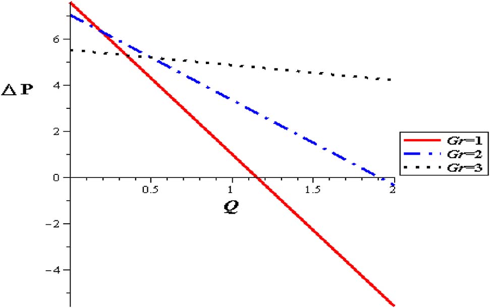
Pressure flow rate profiles with different Gr at (φ = 0.004, α = 0.3, S = 2, δ = 0.1).
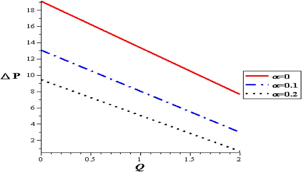
Pressure flow rate profiles with α at (Gr = 2, φ = 0.004, S = 2, δ = 0.1).
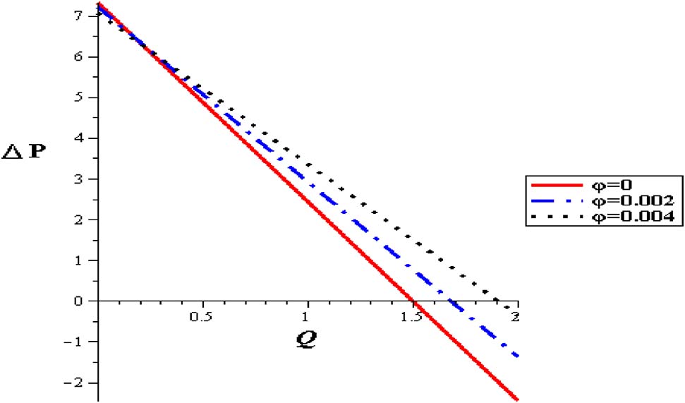
Pressure flow rate profiles with different nanoparticles concentration at (Gr = 2, α = 0.3, S = 2, δ = 0.1).
Figures 16–21 investigate streamlines conceptions for the effect of several variables in the peristaltic phenomenon. This declaration a preferable estimation of the influence of nanofluid which is an original characteristic sine-related with the peristalsis. Figure 16 shows Gr effect on the motion of nanofluid. The scrambled streamlines decrease with Gr growing in all pure fluid and nanofluids cases. The continuity motion of the nanofluid is analyzed in Figure 17. Figure 18 shows that the presence of nanoparticles concentration (φ) decreases the motion of nanofluid. The influence of thermal parameter (S) on assembled streamlines for pure fluid and nanofluid is illustrated in Figure 19. The assembled streamlines rise with enhancing the heat absorption (S). Peristaltic motion property is signified in Figure 20. The crowded streamlines phenomenon with different viscosity parameter (α) is analyzed in Figure 21, where the crowded streamlines rises with an increment in the viscosity parameter (α) i. e. with lowering viscosity of nanofluid.
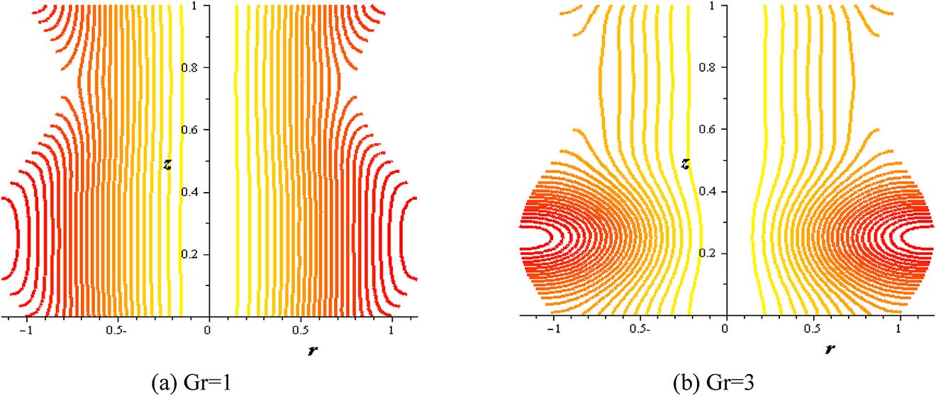
Streamlines with Gr at (Q = 0.1, φ = 0.004, S = 2, δ = 0.2, α = 0.3).
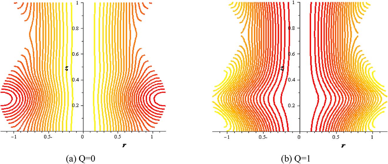
Streamlines with flow rate at (Gr = 2, φ = 0.004, S = 2, δ = 0.2, α = 0.3).
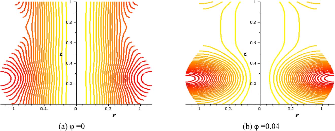
Streamlines with nanoparticles concentration (φ) at (Gr = 2, Q = 0.1, S = 2, δ = 0.2, α = 0.3).
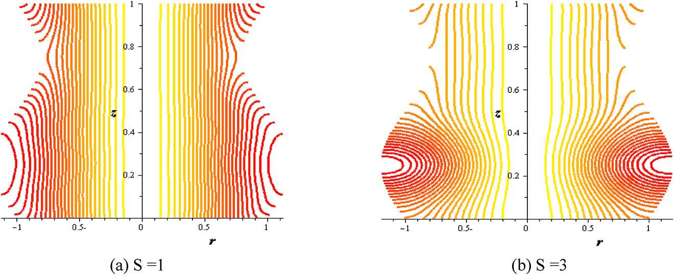
Streamlines with heat source at (φ = 0.004, Gr = 2, Q = 0.1, δ = 0.2, α = 0.3).
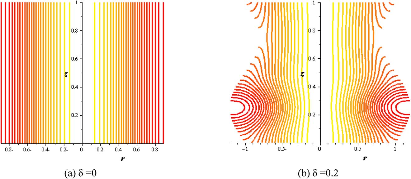
Streamlines with amplitude ratio at (S = 2, φ = 0.004, Gr = 2, Q = 0.1, α = 0.3).
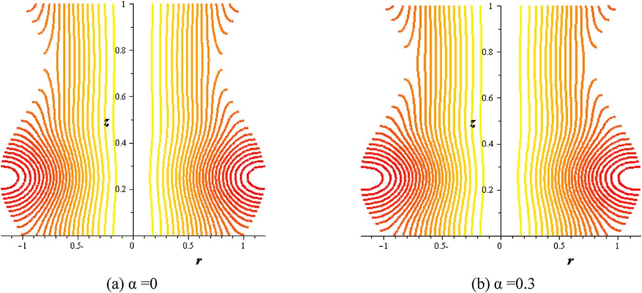
Streamlines with variable viscosity parameter at (S = 2, δ = 0.2, φ = 0.004, Gr = 2, Q = 0.1).
The influence of nanoparticles enhances flow rate and herewith increases the wall shear stress. At the entrance of the pipe, shear stress begins reducing till extreme contraction is attained and subsequently the shear stress increases to the termination of the constriction through the range of wave length. This behavior is also displayed for sequent zones. It is refined until the outlet of the pipe. Identical modalities are supervised in all of figures. The results show that unlike the behavior of shear stress with flow rate (Q), it is high with raising thermal absorption (S), nanoparticles concentration (φ), variable viscosity parameter (α), viscosity parameter (α) and amplitude (δ). The flow is increased at the pipe wall with increasing the thermal sucking. This tendency is actually regular with the previous calculations approaching the axial flow rate and is also close to different investigations of nanofluid peristaltic waves, see Akbar and Nadeem [2] (See Figures 22–27).
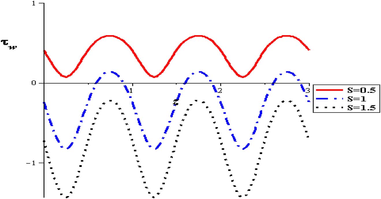
Wall shear stress with heat source at (α = 0.3, δ = 0.1, φ = 0.004, Gr = 2, Q = 0.5).
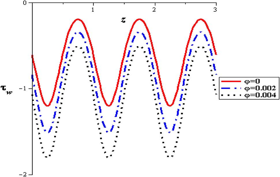
Wall shear stress with nanofluid concentration at (α = 0.3, δ = 0.1, S = 2, Gr = 2, Q = 0.5).
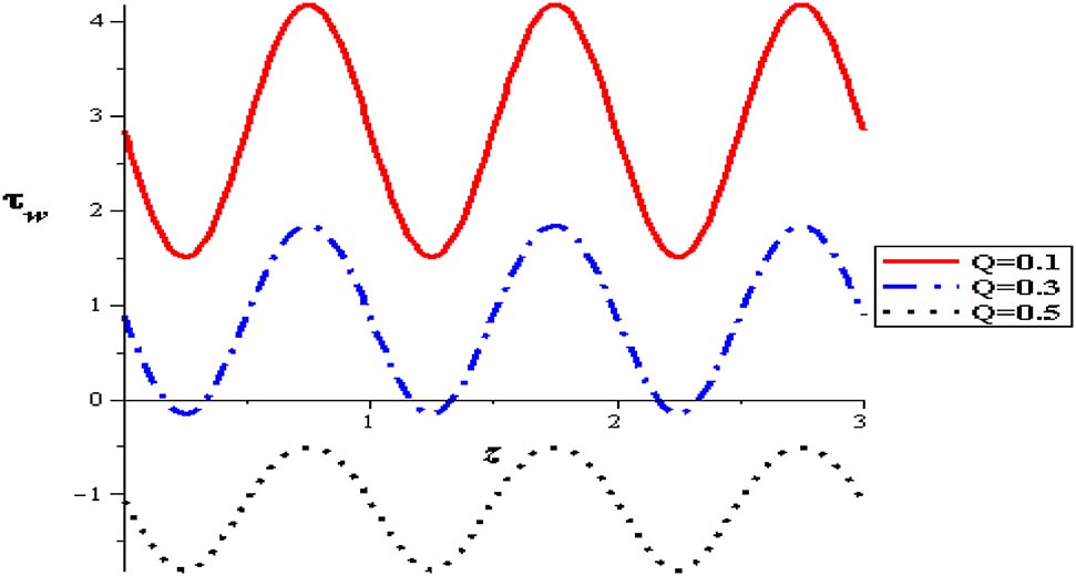
Wall shear stress with flow rate at (φ = 0.004, α = 0.3, δ = 0.1, S = 2, Gr = 2).
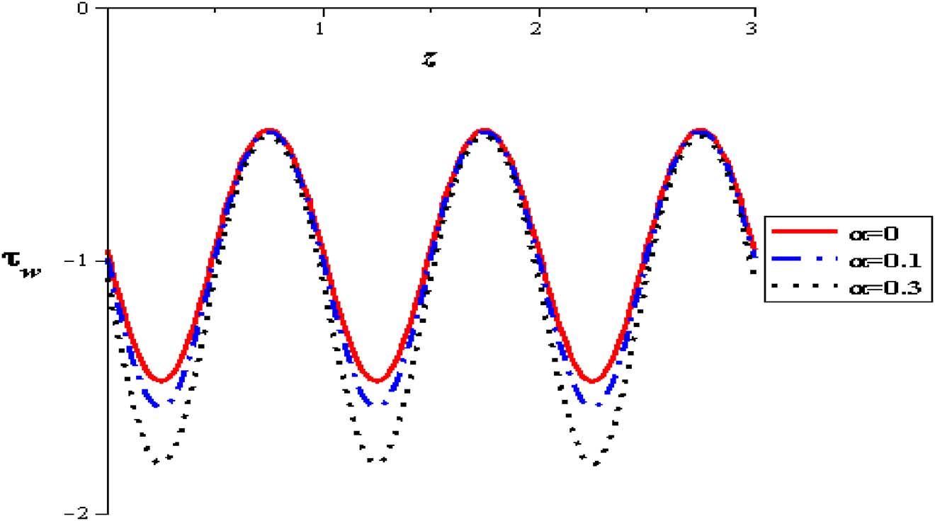
Wall shear stress with variable viscosity parameter at (φ = 0.004, Q = 0.5, δ = 0.1, S = 2, Gr = 2).
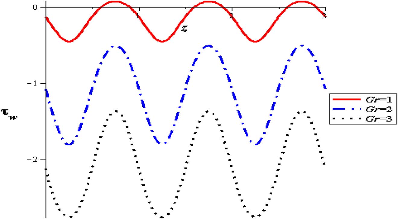
Wall shear stress with gravity at (φ = 0.004, Q = 0.5, δ = 0.1, S = 2, α = 0.3).
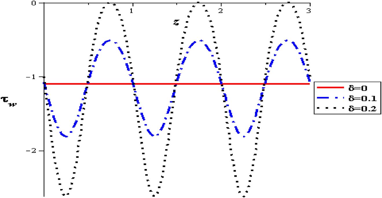
Wall shear stress with amplitude at (φ = 0.004, Q = 0.5, Gr = 2, S = 2, α = 0.3).
Author contribution: All the authors have accepted responsibility for the entire content of this submitted manuscript and approved submission.
Research funding: None declared.
Conflict of interest statement: The authors declare no conflicts of interest regarding this article.
Nomenclature
Symbol Definition Unit r׳,z׳ Polar coordinates cm u׳,w׳ Velocity components cm/s Specific heat at constant pressure Joule/kg.K T Temperature K To Ambient temperature K Constant applied magnetic field Tesla (T) Pressure N/cm2 K Thermal conductivity W/(m·K) Stream function cm2/s θ Dimensionless temperature Dimensionless μ Coefficient of dynamic viscosity Pa.s σ Electrical conductivity Simens/cm ρ Denisty Kg/m3 Reynolds number Dimensionless Mean flow rate Dimensionless Ha Hartmann number Dimensionless F Volumetric flow rate in the wave frame cm3/s λ Wave length cm t` Time sec D Source term of heat Joule S Source term of heat Dimensionless Main tube radius cm Amplitude of the peristaltic wave cm Amplitude ratio in tube Dimensionless Wave number Dimensionless φ Nanoparticles concentration Dimensionless Subscripts f Fluid s Particle nf Nanofluid
References
[1] H. Herwig and G. Wickern, “The effect of variable properties on laminar boundary layer flow,” Der Einfluß temperaturabhängiger Stoffwerte auf laminare Grenzschichtströmung, Wärme-und Stoffübertragung, vol. 20, pp. 47–57, 1986, https://doi.org/10.1007/bf00999737.Suche in Google Scholar
[2] S. Nadeem, N. S. Akbar, and M. Hameed, “Peristaltic transport and heat transfer of a MHD Newtonian fluid with variable viscosity,” Int. J. Numer. Methods Fluid., vol. 63, pp. 1375–1393, 2010, https://doi.org/10.1002/fld.2134.Suche in Google Scholar
[3] A. E. H. A. El Naby, A. El Misiery, and I. El Shamy, “Hydromagnetic flow of fluid with variable viscosity in a uniform tube with peristalsis,” J. Phys. Math. Gen., vol. 36, p. 8535, 2003, https://doi.org/10.1088/0305-4470/36/31/314.Suche in Google Scholar
[4] N. Ali, Q. Hussain, T. Hayat, and S. Asghar, “Slip effects on the peristaltic transport of MHD fluid with variable viscosity,” Phys. Lett., vol. 372, pp. 1477–1489, 2008, https://doi.org/10.1016/j.physleta.2007.09.061.Suche in Google Scholar
[5] S. Nadeem and N. S. Akbar, “Effects of heat transfer on the peristaltic transport of MHD Newtonian fluid with variable viscosity: application of Adomian decomposition method,” Commun. Nonlinear Sci. Numer. Simulat., vol. 14, pp. 3844–3855, 2009, https://doi.org/10.1016/j.cnsns.2008.09.010.Suche in Google Scholar
[6] A. Ebaid, “A new numerical solution for the MHD peristaltic flow of a bio-fluid with variable viscosity in a circular cylindrical tube via Adomian decomposition method,” Phys. Lett., vol. 372, pp. 5321–5328, 2008, https://doi.org/10.1016/j.physleta.2008.05.086.Suche in Google Scholar
[7] N. Eldabe, M. El-Sayed, A. Ghaly, and H. Sayed, “Mixed convective heat and mass transfer in a non-Newtonian fluid at a peristaltic surface with temperature-dependent viscosity,” Arch. Appl. Mech., vol. 78, pp. 599–624, 2008, https://doi.org/10.1007/s00419-007-0181-6.Suche in Google Scholar
[8] J. Shukla and S. Gupta, “Peristaltic transport of a power-law fluid with variable consistency,” J. Biomech. Eng., vol. 104, pp. 182–186, 1982, https://doi.org/10.1115/1.3138346.Suche in Google Scholar
[9] A. E. H. A. El Naby, A. El Misery, and I. I. El Shamy, “Effects of an endoscope and fluid with variable viscosity on peristaltic motion,” Appl. Math. Comput., vol. 158, pp. 497–511, 2004, https://doi.org/10.1016/j.amc.2003.09.008.Suche in Google Scholar
[10] L. Srivastava, V. Srivastava, and S. Sinha, “Peristaltic transport of a physiological fluid,” Biorheology, vol. 20, pp. 153–166, 1983, https://doi.org/10.3233/bir-1983-20205.Suche in Google Scholar
[11] A. A. Khan, R. Ellahi, and M. Usman, “The effects of variable viscosity on the peristaltic flow of non-Newtonian fluid through a porous medium in an inclined channel with slip boundary conditions,” J. Porous Media, vol. 16, 2013, https://doi.org/10.1615/jpormedia.v16.i1.60.Suche in Google Scholar
[12] G. Sucharitha, P. Lakshminarayana, and N. Sandeep, “MHD and cross diffusion effects on peristaltic flow of a casson nanofluid in a duct,” Appl. Math. Sci. Comput., vol. II, pp. 191–201, 2019, https://doi.org/10.1007/978-3-030-01123-9_20.Suche in Google Scholar
[13] N. S. Akbar, “Metallic nanoparticles analysis for the peristaltic flow in an asymmetric channel with MHD,” IEEE Trans. Nanotechnol., vol. 13, pp. 357–361, 2014, https://doi.org/10.1109/tnano.2014.2304362.Suche in Google Scholar
[14] G. Sucharitha, K. Vajravelu, and P. Lakshminarayana, “Effect of heat and mass transfer on the peristaltic flow of a Jeffrey nanofluid in a tapered exible channel in the presence of aligned magnetic field,” Eur. Phys. J. Spec. Top., vol. 228, pp. 2713–2728, 2019, https://doi.org/10.1140/epjst/e2019-900067-2.Suche in Google Scholar
[15] M. M. Bhatti, R. Ellahi, A. Zeeshan, M. Marin, and S. I. Abdelsalam, “Swimming of motile gyrotactic microorganisms and movement of nanoparticles in blood flow through anisotropically tapered arteries,” Front. Phys., Vol. 8, Article 95, pp. 1–9, 2020, https://doi.org/10.3389/fphy.2020.00095.Suche in Google Scholar
[16] S. I. Abdelsalam and M. M. Bhatti, “Anomalous reactivity of thermo-bioconvective nanofluid towards oxytactic microorganisms,” Appl. Math.Mech., vol. 41, pp. 1–14, 2020, https://doi.org/10.1007/s10483-020-2609-6.Suche in Google Scholar
[17] S. I. Abdelsalam and M. M. Bhatti, “New insight into AuNP applications in tumor treatment and cosmetics through wavy annuli at the nanoscale,” Sci. Rep., vol. 9, no. 1, pp. 1–14, Article 260 (2019), https://doi.org/10.1038/s41598-018-36459-0.Suche in Google Scholar
[18] S. I. Abdelsalam and M. M. Bhatti, “The study of non-Newtonian nanofluid with hall and ion slip effects on peristaltically induced motion in a non-uniform channel,” RSC Adv., vol. 8, pp. 7904–7915, 2018, https://doi.org/10.1039/c7ra13188g.Suche in Google Scholar
[19] S. I. Abdelsalam and M. M. Bhatti, “The impact of impinging TiO2 nanoparticles in Prandtl nanofluid along with endoscopic and variable magnetic field effects on peristaltic blood flow,” Multidiscip. Model. Mater. Struct., vol. 14, no. 3, pp. 530–548, 2018, https://doi.org/10.1108/mmms-08-2017-0094.Suche in Google Scholar
[20] I. M. Eldesoky, R. M. Abumandour and E. T. Abdelwahab, “Analysis for various effects of relaxation time and wall properties on compressible maxwellian peristaltic slip flow,” Zeitschrift fur Naturforschung A, vol. 4, no. 4, pp. 317–331, 2019, https://doi.org/10.1515/zna-2018-0479.Suche in Google Scholar
[21] I. M. Eldesoky, S. Abdelsalam, R. Abumandour, M. Kamel, and K. Vafai, “Interaction between compressibility and particulate suspension on peristaltically driven flow in planar channel,” _Appl. Math. Mech., vol. 38, p. 137, 2017, https://doi.org/10.1007/s10483-017-2156-6.Suche in Google Scholar
[22] M. H. Kamel, I. M. Eldesoky, B. M. Maher, and R. M. Abumandour, “ Slip effects on peristaltic transport of a particle-fluid suspension in a planar channel,” Appl. Bionics Biomechanics, 2015, vol. 1, p. 2015, https://doi.org/10.1155/2015/703574.Suche in Google Scholar
[23] G. Sucharitha, M. M. Rashidi, S. Sreenadh and P. Lakshminarayana, “Effects of a magnetic field and slip-on convective peristaltic flow of a non-Newtonian fluid in an inclined non-uniform porous channel with flexible walls,” J. Porous Media, vol. 21, pp. 895–910, 2018, https://doi.org/10.1615/jpormedia.2018020133.Suche in Google Scholar
[24] S. R. Elkoumy, E. I. Barakat, and S. I. Abdelsalam, “Hall and transverse magnetic field effects on peristaltic flow of a Maxwell fluid through a porous medium,” Global J. Pure Appl. Math., vol. 9, no. 2, pp. 187–203, 2013.Suche in Google Scholar
[25] G. Sucharitha, P. Lakshminarayana, and N. Sandeep, “Joule heating and wall flexibility effects on the peristaltic flow of magnetohydrodynamic nanofluid,” Int. J. Mech. Sci., vol. 131–132, pp. 52–62, 2017, https://doi.org/10.1016/j.ijmecsci.2017.06.043.Suche in Google Scholar
[26] G. Sucharitha, K. Vajravelu, and P. Lakshminarayana, “Magnetohydrodynamic nanofluid flow in a non-uniform aligned channel with joule heating,” J. Nanofluids, vol. 8, no. 7, pp. 1373–1384, 2019, https://doi.org/10.1166/jon.2019.1694.Suche in Google Scholar
[27] K. S. Mekheimer, M. S. Mohamed, and T. Elnaqeeb, “Mettalic nanoparticles influence on blood flow through a stenotic artery,” Int. J. Pure Appl. Math., vol. 107, no. 1, pp. 201–220, 2016, https://doi.org/10.12732/ijpam.v107i1.16.Suche in Google Scholar
[28] N. S. Akbar and M. B. Habib, “Peristaltic pumping with double diffusive natural convective nanofluid in a lopsided channel with accounting thermophoresis and Brownian moment,” Microsyst. Technol., vol. 25, pp. 1217–1226, 2019, https://doi.org/10.1007/s00542-018-4094-9.Suche in Google Scholar
[29] N. S. Akbar, M. Shoaib, T. Dharmendra, B. Shashi, and B. O. Anwar, “Analytical approach to entropy generation and heat transfer in CNT-nanofluid dynamics through a ciliated porous medium,” J. Hydrodyn., Ser. B, vol. 30, no. 2, pp. 296–306, 2018, https://doi.org/10.1007/s42241-018-0021-x.Suche in Google Scholar
[30] N. S. Akbar, “Metallic nanoparticles analysis for the peristaltic flow in an asymmetric channel with MHD,” IEEE Transactions on Nanotechnology, vol. 13, pp. 357–361, 2014, https://doi.org/10.1109/tnano.2014.2304362.Suche in Google Scholar
[31] N. S. Akbar, D. Tripathi, Z. H. Khan, and O. A. Bég, “Mathematical modelling of pressure-driven micropolar biological flow due to metachronal wave propulsion of beating cilia,” Mathematical Biosciences, vol. 301, pp. 121–128, 2018, https://doi.org/10.1016/j.mbs.2018.04.001.Suche in Google Scholar
[32] N. S. Akbar, A. Bintul Huda, M. B. Habib, and Tripathi, “Nanoparticles shape effects on peristaltic transport of nanofluids in presence of magnetohydrodynamics,” Microsyst. Technol., vol. 25, pp. 283–294, 2019, https://doi.org/10.1007/s00542-018-3963-6.Suche in Google Scholar
[33] N. S. Akbar and A. W. Butt, “Ferromagnetic nano model study for the peristaltic flow in a plumb duct with permeable walls,” Microsyst. Technol., vol. 25, pp. 1227–1234, 2019, https://doi.org/10.1007/s00542-018-4045-5.Suche in Google Scholar
[34] A. H. Shapiro, M. Y. Jaffrin, and S. L. Weinberg, “Peristaltic pumping with long wavelengths at low Reynolds number,” J. Fluid Mech., vol. 37, pp. 799–825, 1969, https://doi.org/10.1017/s0022112069000899.Suche in Google Scholar
[35] A. Bintul Huda, N. S. Akbar, O. Anwar Beg, and M. Yaqub Khan, “Dynamics of variable viscosity nanofluid flow with heat transfer in a flexible vertical tube under propagating waves,” Results Phys., vol. 7, pp. 413–425, 2017, https://doi.org/10.1016/j.rinp.2016.12.036.Suche in Google Scholar
© 2020 Walter de Gruyter GmbH, Berlin/Boston
Artikel in diesem Heft
- Frontmatter
- Dynamical Systems & Nonlinear Phenomena
- Nonlinear dynamics of ion-acoustic waves in quantum plasmas with exchange-correlation effects
- Dynamical properties of nonlinear ion-acoustic waves based on the nonlinear Schrödinger equation in a multi-pair nonextensive plasma
- Taming of the Hopf bifurcation in a driven El Niño model
- Exact force-free plasma equilibria with axial and with translational symmetries
- Initial-boundary value problems for the one-dimensional linear advection–dispersion equation with decay
- Hydrodynamics
- Peristaltic thrusting of a thermal-viscosity nanofluid through a resilient vertical pipe