Numerical and Experimental Comparative Analysis of Ballistic Performance of Packages Made of Biaxial and Triaxial Kevlar 29 Fabrics
-
Justyna Pinkos
 and
Zbigniew Stempien
and
Zbigniew Stempien

Abstract
The objective of this study is a comparative analysis of the ballistic effectiveness of packages made of biaxial and triaxial Kevlar 29 fabrics under the hitting of Parabellum 9×19 bullet. We conduct both numerical simulations using the LS-Dyna program and experimental research in a ballistic research laboratory. Based on the comparative analysis of the results from the numerical and experimental research, demonstrated differences exist in the ballistic effectiveness between the packages made of biaxial fabrics and the packages consisting of triaxial fabrics. For this purpose, the residual velocity of the bullet is analyzed in detail in terms of the maximum deformation cone, the shape of the deformation cone, and the distribution of stress for the textile ballistic packages. It is established that the packages made of triaxial fabric show a considerably smaller deformation cone compared with the packages made of biaxial fabric, a more favorable shape of the deformation cone from the perspective of ballistic trauma and distribution of stress similar to materials with isotropic properties. Poorer properties are recorded for these packages in the case of the minimum number of layers necessary for stopping the bullet, which arises from the open-work structure of the fabric.
1 Introduction
Multiaxial fabrics are perspective textile structures for use in soft ballistic packages. Existing research shows that the geometrical structure of the fabric, regardless of the raw material used, has a considerable influence on its ballistic effectiveness [1,2,3,4,5,6]. Thus, it is not unreasonable to assert that textile multiaxial structures used in soft ballistic packages may result in higher ballistic effectiveness compared with traditional biaxial fabrics, particularly in the area of decreasing the ballistic trauma scale. Compared with traditional biaxial fabrics, multiaxial fabrics may contain more than two mutually interweaving systems of threads in their structure. During a bullet impact into a multiaxial fabric, the shockwave spreads radially along with all systems, resulting in the fabric area absorbing more kinetic energy from the bullet than in a biaxial fabric. This may have a considerable influence on the parameters of the deformation cone formed and consequently the physiological effects of ballistic shock. A triaxial fabric with a base weave is the basic textile multiaxial structure. The first works about the production of triaxial fabrics were conducted in the first half of the twentieth century. At that time, making this type of fabric was only possible manually. The obtained structure of the triaxial fabric had a limited width and was generated of natural fibers. An extremely difficult task was to prepare a machine for the commercial generation of triaxial fabrics, particularly made of highly resistant fibers, for ballistic protection.
Scardino and Ko conducted one of the first research studies featuring a comparative analysis of the strength properties of a biaxial fabric concerning a triaxial fabric [7]. The authors carried out tests of shearing and resistance to pulling out with a bullet. The tested fabrics were made of polyester yarn. As a result of the conducted shearing tests, it was noticed that the triaxial fabric achieved higher values of shearing stress than the biaxial fabric. Further tests conducted by Scardino and Ko for biaxial and triaxial fabrics consisted of an organoleptic assessment of damage in the structure of the fabrics during pulling out with a bullet. Figure 1 shows photographs of samples of the biaxial and triaxial fabrics after the test.
![Figure 1 Samples after pulling out with a bullet for (a) biaxial and (b) triaxial fabrics [6].](/document/doi/10.2478/aut-2020-0015/asset/graphic/j_aut-2020-0015_fig_001.jpg)
Samples after pulling out with a bullet for (a) biaxial and (b) triaxial fabrics [6].
Based on the organoleptic assessment of the samples of the fabrics, significant damage to the threads of the warp and weft in the biaxial fabric was noticed. Concerning the triaxial fabric, no destructive damage to the threads was observed. Based on the results of the research, it was concluded that the triaxial fabric has a structure similar to the isotropic one, allowing for the distribution of the deformation on a larger area of the structure.
Experimental tests of the ballistic effectiveness of packages made of triaxial and biaxial fabrics based on polyamide fibers were carried out by Harle et al. [8]. It was hypothetically assumed that the triaxial fabrics should have better ballistic properties than the biaxial fabrics. This was mainly believed to arise from the higher isotropy of the triaxial fabric, which would lead to more regular distribution of stress around the bullet impact point. In contrast, it was hypothetically assumed that the ballistic resistance of the packages consisting of triaxial fabrics due to hexagonal openings in the structure of the fabric will be smaller than for the packages made of biaxial fabrics. A steel bullet in the shape of a cylinder was used in the research. The assessment of the ballistic effectiveness of the packages consisting of the biaxial and triaxial fabrics was carried out by determining the minimum number of layers to ensure the nonpenetration of the package. Based on the conducted tests, it was identified that the minimum number of layers used to ensure the nonpenetration of the package of the biaxial fabrics was smaller than for the package of the triaxial fabrics. It was concluded that this was a result of the impact of the hexagonal openings in the structure of the fabric, which gives it considerable transparency.
Egres et al. [9] numerically and experimentally tested the ballistic resistance of monolithic panels composed of non-orthogonal-braided biaxial and triaxial Kevlar® fabric architectures. It was concluded that against high-energy deformable handgun bullet threats, nonorthogonal biaxial and some triaxial-braided Kevlar® fabrics demonstrate both improved ballistic V50 and backface deformation resistance over orthogonal biaxial-woven Kevlar® fabrics of comparable basis weight. It was reported that these same nonorthogonal architectures exhibit equivalent or improved fragmentation threat protection over typical biaxial-woven Kevlar® fabric constructions.
A wide range of materials, fiber architectures, and manufacturing methods are available to make fiber composite components for ballistic armors. Approaches using triaxial braid that performs with various resin combinations have been developed for these applications. During testing, triaxial-braided composites, usually the failure modes, limit velocity v50, failure patterns, and so on, have been analyzed. Roberts et al. conducted the comparable impact tests using a soft gelatin projectile [10] to identify failure modes that occur at high strain energy density during impact loading of aluminum plates and composites plates made of triaxial carbon fiber braid having a 0/+60/−60 architecture. In the case of aluminum plates, a large hole formed as a result of crack propagation from the initiation site at the center of the plate. For composite plates, fiber tensile failure occurred in the back ply at the center of the plate. Cracks then propagated from this site along with the ±60° fiber directions until triangular flaps opened to form a hole. Damage in the composites was localized near the impact site, while cracks in the aluminum extended to the boundaries.
In the research conducted by Yen and Caiazzo [11], experimental and numerical analyses were used to evaluate the ballistic performance of various 2D- and 3D-woven composites of S2-Glass/Epoxy material. The selected woven constructions include plain weave laminate, triaxial weave laminate, 3D orthogonal weave, 3D 4-step-braided weave, and 3D triaxial weave. Analyses were performed to predict the perforation limit velocity (v50) of the composite panels subjected to a 0.22 caliber fragment simulation projectile impact. Based on the results achieved, it was indicated that the limit velocity v50 of plain weave laminate was slightly higher than the limit velocity of the other composites.
In the research by Liu et al. [12], numerical analysis and ballistic impact tests were conducted to investigate the impact response and damage of triaxial-braided containment fan case material with a blade-like projectile. From the experimental and numerical results, it was concluded that the main failure modes of carbon/epoxy triaxial-braided composite materials impacted by high-velocity blade-like projectiles are fiber shear fracture, matrix crush in the impacting surface, fiber tensile fracture, matrix cracking, fiber pull-out, and delamination in the exiting surface.
The comparative analysis of the high-velocity impact response and damage evolution of the triaxial-braided and satin-woven composites was conducted by Haijun et al. [13]. Experimental results indicated that the triaxial-braided composites had an improved ballistic resistance and higher ballistic limit than satin-woven composites. The main failure modes for both architectures were similar and were related to fiber shear failure and matrix crush failure in the impact surface and fiber tensile failure, fiber pull-out, matrix cracking, and delamination in the exit surface. The damaged area in the exit surface was diamond-shaped for satin-woven composites while rounded or elliptic for triaxial-braided composites according to projectile geometry.
The mesoscale model method based on yarn architecture of triaxial-braided composites was used to investigate its dynamic response using the LS-Dyna solver by Liu et al. [14]. Numerical simulations were conducted on single-layer-braided textile. It was found that the main response of triaxial-braided textile under projectile impact is the transverse wave propagation, yarn tension, yarn fracture, and pull-out successively. In the initial stage of impact, the yarns are still in the crimped state, and the interaction force between the projectile and textile is very low. After the yarns are straightened, the interaction force and yarn strain energy increase rapidly and reach its maximum value before the yarn fracture. Yarn strain energy, yarn kinetic energy, and friction sliding energy are the main energy absorption modes. The yarn strain energy and kinetic energy increase first and decrease later, while the sliding energy increases significantly in the perforation process. The boundary constraint has an evident influence on the deformation, interaction force, and energy absorption of braided textile. The boundary conditions change the proportional relations of yarn internal energy and yarn kinetic energy. It also influences the distributions of strain energy of yarns in each direction. The friction factor has a great influence on ballistic performance. When the friction factor is smaller, the yarns are apt to sliding away and give rise to the deduction of energy absorption.
Ballistic impact experiments to study the heat generated in the material due to projectile velocity and penetration damage were performed on triaxially braided polymer matrix composites by Johnston et al. [15]. Triaxially braided (0/+60/−60) composite panels were manufactured with the T700S standard modulus carbon fiber and two epoxy resins. The PR520 (toughened) and 3502 (untoughened) resin systems were used to make different panels to study the effects of resin properties on temperature rise. The ballistic impact tests were conducted using a single-stage gas gun, and different projectile velocities were applied to study the effect on the temperature results. Temperature contours were obtained from the back surface of the panel during the test through a high speed, infrared thermal imaging system. The contours show that high temperatures were locally generated and more pronounced along with the axial tows for the T700S/PR520 composite panels, whereas, tests performed on T700S/3502 composite panels, using similar impact velocities, demonstrated a widespread area of lower temperature rises. Overall, the impact experimentation showed temperatures exceeding 252°C in both composites, which is well above the respective glass transition temperatures for the polymer constituents.
Steckel conducted an assessment of the ballistic effectiveness of biaxial and triaxial fabrics in terms of resistance to puncture with cold steel [16]. For the tests, biaxial and triaxial fabrics made of the same raw material and with a similar surface mass were used. A double-edged knife was also used. The layer of fabric was fixed in steel clamps, and three places of impact with the knife were then determined. Based on the conducted tests, the size of the damage in the structure of the biaxial and triaxial fabrics was assessed in organoleptic terms. In the biaxial fabric, the breaks were in one direction and along the threads of the weft. Concerning the sample of the triaxial fabric, it was noticed that the damage does not have the one-directional shape of the breakage. Based on this research, it was concluded that the triaxial fabric is a structure similar to the isotropic one, allowing for the distribution of the deformation on a larger area of the structure.
Messiry conducted comparative analyses of resistance to puncture with the cold steel of the single layers of the biaxial and triaxial fabrics [17]. In the experimental analysis, the following objects of research were used: a biaxial fabric of silk, a biaxial fabric with the trade name Kevlar 29, a triaxial fabric with the trade name Kevlar 29, and a triaxial fabric of polyester (PES) yarn. Samples of the fabrics were fixed in steel frames in the shape of a wheel. The surface of the samples of the fabrics was subject to a knife with a diameter of 25 mm. Based on the analysis, it was concluded that in the biaxial fabrics, single threads of the weft and warp were damaged in the place of the blade, whereas the other threads were extended. Concerning the triaxial fabrics, increased resistance to penetration was identified by ~20% in relation to the biaxial fabrics. It was concluded that as a result of the increase in the number of layers, one can increase the resistance to penetration.
Messiry and Eltahan [18] continued the tests of resistance to penetration with cold steel determining the values of the penetration strength for biaxial and triaxial fabrics and knits. The tests were carried out for single layers and packages. During the research, the knife was fixed in a movable clamp that hit the sample with a velocity of ~3.5 m/s. First, an organoleptic analysis of damage was conducted for single textile structures subjected to the knife. It was concluded that the damage to the knit made of PES yarn and to the biaxial fabric made of HTPE fibers include places of the direct impact of the knife edge. In the structure of the triaxial fabric with the trade name Kevlar 29, the damage was in the place of impact of the knife-edge with the characteristic movement of fragments of the damaged fibers noticed in relation to the fabric surface. In the next stage, the values of the penetration strengths were examined depending on the number of layers of the package. There was also analyzed impact of the elastic fiber Lycra in the PES warp knit depending on the number of layers on the penetration strengths. Based on the analysis of the results, it was concluded that the highest resistance to penetration with cold steel was demonstrated by the Vectran triaxial fabric. Concerning the biaxial fabric made of HTPE fibers and the PES knit with a share of 16% of Lycra fiber, the lowest resistance to penetration was identified. It was also concluded that the increased share of the elastic synthetic fiber Lycra in the structure of the warp knit causes the increased resistance to penetration with a knife. In the final stage, there were examined penetration strengths for three triaxial fabrics depending on the number of layers. As a result of the conducted tests, it was concluded that the highest resistance to penetration with cold steel was demonstrated by the Vectran triaxial fabric compared with the Kevlar 29 fabric and PES. The increased number of layers in the package contributed to the increased penetration strength for the tested triaxial fabrics.
The published results of the comparative analyses of the biaxial fabrics concerning the triaxial fabrics indicate better strength properties of the triaxial fabrics, that is, shearing stress or resistance to pulling out with a bullet. This is certainly a result of the impact of the triaxial fabric structure, which contains more than two mutually interweaving systems of threads. The triaxial fabric has a structure similar to the isotropic one, allowing for the distribution of stress and deformation on a larger area. In addition, tests of resistance to penetration with cold steel indicate the advantage of the triaxial fabric. It was concluded that compared with the biaxial fabric, it has higher resistance by 20%. In contrast, the published results of the research show that the structure of the triaxial fabric influences the minimum number of layers needed to stop a bullet. Compared with the biaxial fabric, the number of layers needed to brake a bullet was higher. The hexagonal openings in the structure of the triaxial fabric, which give considerable transparency, were the main influence for this.
The results presented in the literature show that triaxial fabrics may, in many applications, have more favorable strength properties than biaxial fabrics. Therefore, the objective of the research presented in this article is a comparative analysis of the ballistic effectiveness of packages made of biaxial and triaxial Kevlar 29 fabrics. The tests consist of conducting numerical research using finite element analysis in the LS-Dyna program and then carrying out verification using experimental research in a ballistic research laboratory. The multilayer soft ballistic shields consist of 6, 12, 16, 20, 24, and 30 layers of the biaxial and triaxial fabrics. The boundary condition adopted in the numerical and experimental research consists of fixing four edges. Parabellum 9 × 19 mm FMJ bullets from Winchester were used for the research. The impact velocity of the bullets reaches 406 ± 10 m/s, which corresponds with the class of bulletproof II, according to the NIJ 0101.06 standard. As a result of the conducted numerical and experimental tests, the residual velocity of the bullet, the maximum deformation cone, the shape of the deformation cone, and the distribution of stress over time for textile ballistic packages are analyzed.
2 Objective of research
Biaxial (Changzhou Utek Composite Co. Ltd., China) and triaxial fabrics (Triaxial Structures Inc., USA), made of the same yarn Kevlar 29 with a linear mass of 1500 dtex, were used in this study. The fabrics have a comparable surface mass of ~200 g/m2. The number of threads of the weft and warp in the biaxial fabric was 70 threads/dm, whereas the number of threads in each system of the triaxial fabric was 9 threads/inch.
3 Materials and methods
3.1 Geometrical model of biaxial and triaxial fabrics
In numerical research, the geometrical models of the fabrics were prepared based on the actual dimensions of the biaxial and triaxial fabrics. For this purpose, the samples of the fabrics were immersed in epoxy resin, and after their hardening, the layers were removed along with the weft and warp 0.1 mm thick using a miller. Photographs were then taken using a stereoscopic microscope OLYMPUS SZX-10. After the conducted microscopic observations, the average values of the height and width of the cross-section of the thread forming the actual biaxial and triaxial fabrics were determined. The average values of amplitude and period in the route of the threads in the warp and weft systems were also determined. From the photographs shown in Figure 2, it was observed that the oval shape was adopted for the threads of the warp and weft of the biaxial fabric, whereas the convexo-convex shape was adopted for the threads of the warps and the weft of the triaxial fabric (Figure 3).

Cross-section of biaxial fabric with the marked out the oval shape along with the height and width values.

Cross-section of triaxial fabric with the marked out the convexo-convex shape along with the height and width values.
Based on the marked out dimensions of the cross-section and the periodic route of the thread, in the next stage, a layer of the 3D model of the fabrics with dimensions of 20 cm × 20 cm in the Ansys ICEM CFD program was prepared. Figure 4 shows the fragments of the actual geometrical structure of the biaxial and triaxial fabrics as well as their numerical models.

Fragment of the actual and numerical geometrical structure of the (a) biaxial and (b) triaxial fabrics.
In the next stage, the FE mesh of the biaxial and triaxial fabrics was generated by the discretization of the yarns with 3D Hexa/Solid elements using the Ansys ICEM CFD program. Four elements in the case of triaxial fabric and three elements in the case of biaxial fabric were used in the cross-section of the yarns to sufficiently capture the yarns cross-sectional shapes (Figure 5). The dimensions of the finite elements in yarns cross-section are presented in Figure 5. The length of the unit finite elements, which were used in the discretization of yarns in the triaxial and biaxial fabrics, was approximately 0.35 and 0.29 mm, respectively (Figure 5).

The dimensions in mm of the unit finite elements that were used in the discretization of (a) triaxial and (b) biaxial fabric yarns.
Based on the assumed way of discretization of the yarns cross-section and the dimensions of the unit finite elements, in the next stage, the FE mesh of the one layer of fabric with dimensions of 20 cm × 20 cm was generated by using the Ansys ICEM CFD program. The discrete model of fabric was represented by 517,934 elements and 1,040,280 nodes per one layer for triaxial fabric and 588,000 elements and 1,177,680 nodes per one layer for biaxial fabric.
The numerical tests were conducted for packages consisting of 6, 12, 16, 20, 24, and 30 layers of biaxial and triaxial fabrics. The Hewlett-Packard HP Z8 G4 workstation of 24 cores was used for calculations. The location of the Parabellum 9 × 19 mm FMJ bullet was determined so that it will centrally hit the interlace of the fabric threads. Figures 6 and 7 present the fragment of the cross-section through the package consisting of 30 layers of the biaxial and triaxial fabrics along with the bullet.

Cross-section through the package consisting of 30 layers of biaxial fabrics along with the bullet.

Cross-section through the package consisting of 30 layers of triaxial fabrics along with the bullet.
3.2 Geometrical model of bullet
The bullet was prepared for the numerical tests and consisted of a core and a jacket. The geometrical model of the bullet was prepared based on factory data in the Ansys Design Modeler program (Figure 8). In the next stage, using the Ansys ICEM CFD program, the FE meshes were generated assuming for the core and jacket the dimension of edges to 0.5 mm and a Tetra/Solid mesh.

Parabellum 9 × 19 mm FMJ bullet: (a) geometrical model of the bullet and (b) cross-section through the geometrical model.
3.3 Initial and boundary conditions
A significant issue in the finite element method is the adoption of the appropriate initial and boundary conditions of the simulation. In the numerical tests, the contact AUTOMATIC_SURFACE_TO_SURFACE was used, for which appropriate values of the dynamic (μd) and static (μs) friction coefficients were defined. The values of the coefficients were adopted based on the literature, and, in particular, the information contained in Refs. [19,20,21,22,23]. The following contacts along with the dynamic μd and static μs friction coefficients were defined for the tested bullet impact phenomenon in the ballistic package:
| Between systems of threads of the weft and warp being in contact with the area of one layer | – | μd = 0.10; μ s = 0.10 |
| Between systems of threads of neighboring layers | – | μd = 0.10; μs = 0.10 |
| Between the jacket and core of the bullet | – | μd = 0.80; μs = 0.80 |
| Between the bullet jacket and systems of threads in subsequent layers | – | μd = 0.28; μs = 0.30 |
| Between the bullet core and systems of threads in subsequent layers | – | μd = 0.28; μs = 0.30 |
Next, the boundary conditions for the edging knots of the ballistic package were adopted, which were fixed so that they did not move in any direction of the system of xyz coordinates. For this purpose, the number of degrees of freedom of the edging knots of meshes of particular layers of the package was adequately reduced by the BOUNDARY_SPC_SET option. In the final stage of preparation of the ballistic package model for numerical calculations, material cards were selected along with parameters based on the data presented in the literature for aramid threads of Kevlar 29 with a linear mass of 1500 dtex [1, 24, 25] and the bullet [23, 26, 27]. For the fabrics made of para-aramid threads of Kevlar 29, the material card *MAT_ PLASTIC_KINEMATIC (Table 1) was adopted, whereas for the lead core (Table 2) and jacket (Table 3) of the bullet, the card *MAT_SIMPLIFILED_JOHNOSN_COOK was selected.
Material parameters for aramid threads Kevlar 29, *MAT_PLASTIC_KINEMATIC
| RO density, kg/m3 | Young E modulus, Pa | Poisson coefficient PR | Yield strength SIGY, Pa | Breaking deformation FS, % |
|---|---|---|---|---|
| 1,440 | 7.5e + 8 | 0.3 | 1.24e + 9 | 3.6 |
Material parameters for the lead core, *MAT_SIMPLIFILED_JOHNOSN_COOK
| RO density, kg/m3 | Young E modulus, Pa | Poisson coefficient PR | Constant A | Constant B | Constant N | Constant c |
|---|---|---|---|---|---|---|
| 11,300 | 1e + 09 | 0.42 | 5e + 6 | 4e + 7 | 0.5 | 0.628 |
Material parameters for the bullet jacket, *MAT_SIMPLIFILED_JOHNOSN_COOK
| RO density, kg/m3 | Young E modulus, Pa | Poisson coefficient PR | Constant A | Constant B | Constant N | Constant c |
|---|---|---|---|---|---|---|
| 8,940.9 | 1.3e + 11 | 0.375 | 112e + 6 | 5050e + 5 | 0.42 | 0.009 |
For the generated FE models of ballistic packages and bullet as well as assumed initial and boundary conditions, the computation time using the LS-Dyna solver depends on number of layers in ballistic packages and assumed simulation time. For both triaxial and biaxial ballistic packages of the same number of layers, the computation time was similar due to a comparable number of nodes and elements in the FE models of these fabrics. When solving the problem of hitting a bullet through 30 layers of triaxial and biaxial fabrics, the computation time was the longest and was approximately 10 days for the assumed simulation time equal to 0.5 ms.
3.4 Methodology of experimental research
The results of the numerical tests with the use of models of the triaxial and biaxial fabrics were verified experimentally in the ballistic tunnel, the scheme of which is presented in Figure 9.

Scheme of the station for ballistic tests: 1 – ballistic gun; 2 – bullet trajectory; 3 – set of gates for measurement of bullet impact velocity; 4 – steel fixing frames along with the textile package; 5 – camera; 6 – set of gates for measurement of bullet residual velocity; and 7 – bullet catcher with plastic material (plasticine).
The first element of the ballistic line was the ballistic gun in the form of the universal ballistic instrument, which was made by Arms Factory “Łucznik” (Poland). The ballistic gun was fixed to the stationary base. The shooting was carried out at a constant distance from the sample and with a 90º bullet impact angle. The universal ballistic instrument consisted of a velocity ballistic barrel with a diameter of 9 mm. Another element of the equipment of the ballistic tunnel was a system of gates for measurement of the impact and bullet residual velocities. Due to the use of the system of gates for measurement of the impact bullet velocity, it was possible to detect the bullet location approximately 10 cm before the ballistic package and a triggering signal could be generated for releasing the registration process in the camera. Between the gate for the measurement of the impact velocity and the gate for the measurement of the bullet residual velocity, steel frames were positioned to fix the ballistic package. The bullet penetration process of the package is captured by a CORDIN 535D camera (USA) capable of capturing images up to 1 million frames per second in a resolution of 1000 × 1000 pixels.
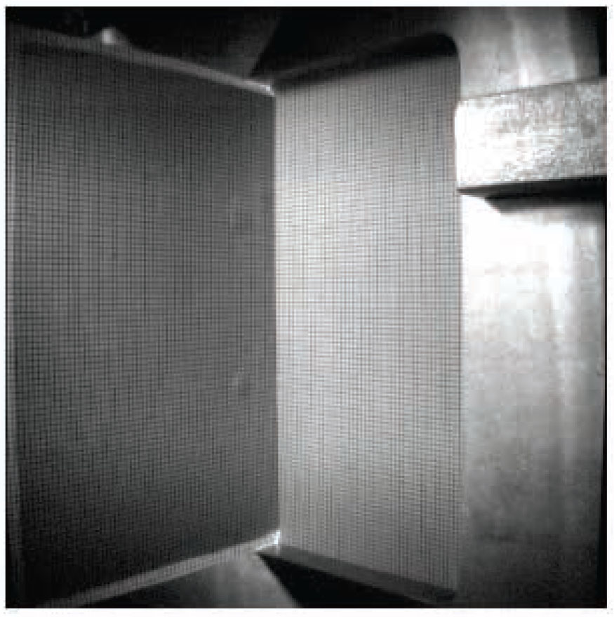
The textile ballistic packages of biaxial and triaxial Kevlar 29 fabrics before shooting were fixed in a handle (Figure 10). The ballistic packages were fixed between two steel frames. The frames were clasped in bottleneck places using clamps. As a result of such a fixture, the movement of the package in the fixing point was approximately equal to zero during the numerical tests. In reality, during the shooting, small protractions of the package layers from the fixture area were observed, particularly the threads in contact with the bullet front. The dimensions of the surface of the sample absorbing the bullet energy were constant at 20 × 20 cm, identical to the numerical tests.

Method of fixing the ballistic packages in steel frames’ view from the side of the deformation cone and the side of the bullet impact.
The textile ballistic packages made of the biaxial and triaxial Kevlar 29 fabrics were subject to shooting with the Parabellum 9 × 19 mm FMJ cartridge. Table 4 includes the basic technical parameters of this bullet.
Technical data of Parabellum 9 × 19 mm FMJ cartridge by Winchester
| Parameter | Value or description |
|---|---|
| Caliber, mm | 9 mm Parabellum |
| Bullet type | FMJ |
| Cartridge length, mm | ~29 |
| Bullet mass, g | 8 |
| Bullet initial velocity, m/s | 406 ± 10 |
| Kinetic energy, J | ~640 |
For a series of shots to the textile ballistic packages, one package of cartridges was used to avoid dispersion in the impact velocity size. The average velocity of the bullets was 406±10 m/s, which corresponds with the class of bulletproof II, according to NIJ Standard 0101.06 [28]. During the experimental tests at the ballistic research laboratory for each package, there was one shot with the zero angle of impact in the center of the sample. For x = 0 and y = 0, the bullet impact velocity and residual velocity were measured at the same time in the case where the package was shot through. A series of the measurements for each ballistic package was conducted three times, and the average value was calculated from the measured velocities. Using one of the most modern methods for the measurement of the deformation cone using a camera for quick registration, a sequence of deformation of the ballistic package accruing over time was registered. The camera registration angle a in relation to the plane of the ballistic package was constant for all the analyzed variants. Figure 11 presents the scheme of the registration process of the deformation cone of the package fixed in the frames.

Scheme of the registration process of the deformation cone by the camera.
To measure the height of the deformation cone, before testing the ballistic packages, 1×1 mm grid sheet was fixed between frames (x–y plane) and the second 1×1 mm grid sheet was fixed in 0-y-z half-plane. The fixed millimeter sheets were then registered by a camera for the fixed angle α (Figure 12).
Photograph from the experimental test for the millimeter sheets fixed in frames.
The height of deformation cone in textile ballistic packages was finally determined by overlapping the partial transparency image of the fixed millimeter sheets on the images registered during testing the ballistic packages and counting the number of millimeter lines form the base of deformation cone to its apex (Figure 13). The angle α and the camera lens parameters were kept the same during registering the millimeter sheets and ballistic packages.

The way of measuring deformation cone in textile ballistic packages.
4 Results of numerical and experimental tests
4.1 Bullet residual velocity
First, while assessing the ballistic resistance of the packages consisting of the biaxial and triaxial fabrics, the residual velocity of the bullet in the numerical and experimental tests was analyzed. Figure 14 presents the distribution of the residual velocity as a function of the number of layers of the ballistic packages consisting of biaxial and triaxial fabrics. As it can be seen, both numerical and experimental analyses showed that the residual velocity for the triaxial ballistic packages is higher than for the biaxial ballistic packages taking into account the same number of layers which corresponded the same areal density of both packages. As it can be seen, both numerical and experimental analyses showed that the residual velocity for the triaxial ballistic packages is higher than for the biaxial ballistic packages taking into account the same number of layers or areal density in both packages.

Distribution of residual velocity as a function of the number of layers of the packages consisting of the biaxial and triaxial fabrics.
While assessing the ballistic effectiveness from the perspective of the minimum number of layers in the ballistic package needed to stop the bullet, it was concluded that for the ballistic package of the biaxial fabrics consisting of 16 layers, it was not shot through. Concerning the triaxial fabric, 22 layers in the ballistic package allowed to brake the bullet in the multilayer structure.
The larger number of the layers in the ballistic package consisting of the triaxial fabrics needed to stop the bullet is a result of an impact of its structure, which has considerable transparency in relation to the biaxial fabric. The experimental verification of the obtained results of the numerical tests of the ballistic packages showed their similarities in terms of the minimum number of the layers needed to stop the bullet. Larger values of the bullet residual velocity obtained in the experimental tests compared with results from the numerical tests may arise from the possibility of pulling out of the stuck layers of the ballistic package from the frames, which does not exist in the numerical tests due to the jam of all the edging knots.
To assess the impact of the geometry of the open-work structure of the triaxial fabric concerning the compact structure of the biaxial fabric, Figures 15 and 16 show the views from the numerical tests of shooting through the ballistic packages consisting of 6 and 12 layers of the tested fabrics.

Views from shooting through the ballistic packages consisting of six layers of the fabrics: (a) biaxial and (b) triaxial.

Views from shooting through the ballistic packages consisting of 12 layers of the fabrics: (a) biaxial and (b) triaxial.
The results presented in Figures 15 and 16 show that the geometry of the fabric weave of the tested fabrics has a considerable influence on the ballistic resistance of the soft packages. The open-work weave of the triaxial fabric had a greater influence on the possibility of quick shooting through the ballistic packages consisting of 6 and 12 layers than in the case of the packages of the biaxial fabrics. This was particularly visible in the case of the ballistic package consisting of 12 layers. Then, at t = 0.12 ms, the package of 12 layers of the triaxial fabrics is shot through, whereas shooting through the package of 12 layers of the biaxial fabrics takes place at t = 0.19 ms. This is a result of the impact of the geometry of the plain weave of the biaxial fabric characterized by the compact and built-up structure.
4.2 Maximum height of deformation cone in textile ballistic packages
In the next stage, the assessment of the ballistic effectiveness of the textile packages was analyzed from the perspective of the maximum deformation cone. Figure 17 presents the results of the maximum value of the cone depending on the number of layers of the ballistic package made of the biaxial and triaxial fabrics.
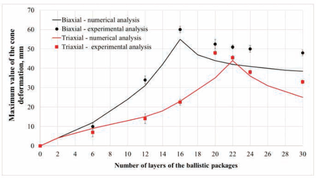
Maximum value of the cone depending on the number of layers of the ballistic package made of the biaxial and triaxial fabrics.
The obtained results of the maximum deformation cone in the numerical and experimental tests for the ballistic packages of the biaxial and triaxial fabrics show the existence of two characteristic tendencies: accruing and decreasing. The use of a larger number of layers of the ballistic package increases the deformation cone. The accruing curve stops for the same number of layers of the package during the numerical and experimental analyses both for the biaxial and triaxial fabrics. As a result of decreasing the height of the maximum deformation cone during the nonpenetrating shooting in the numerical tests, smaller values in the experimental research were achieved.
This could arise from pulling out of the stuck layers of the ballistic package from the frames during the experimental tests, which did not occur in the numerical analyses where the edges of each layer of the tested package were stuck by the BAUNDARY SPC-SET function. As a consequence, this had an influence on the achievement of smaller values of the maximum cone in the numerical tests than in the case of the experimental tests. For the minimum number of layers of the ballistic package of the biaxial fabrics needed to stop the bullet in the numerical tests, the value of the maximum deformation cone was 55 mm, whereas for the package of the triaxial fabrics, it was 44 mm. The tendency to achieve larger values of the cone in the case of the packages of the biaxial fabrics was confirmed experimentally. An analysis of these results showed that the maximum value of the deformation cone for the package consisting of 30 layers of the biaxial fabrics was 48 mm, whereas for the package of the triaxial fabrics, this value was smaller and was 33 mm.
To assess the maximum deformation cone in the numerical tests, the side view for the 30th layer of the ballistic packages was analyzed. Figure 18 presents the selected views for the 30th layer of the ballistic package of the biaxial and triaxial fabrics along with the distribution of deformation.

Side views of the accruing deformation cone for the packages of the fabrics: (a) biaxial and (b) triaxial.
Based on the results shown in Figure 18, it was concluded that in the numerical tests, the value of the maximum deformation cone was 38.5 mm for the ballistic package of the biaxial fabrics, whereas for the package of the triaxial fabrics, it was 25 mm. A considerable influence on the achievement of the smaller value of the deformation cone for the ballistic package of the triaxial fabrics is a result of the influence of the structure of this fabric, characterized by three systems of threads. This allowed us to obtain a larger surface deformation, whereas the maximum arrow of deflection in the bullet impact place was smaller.
4.3 Shape of deformation cone in textile ballistic packages
During the impact of the bullet into the ballistic packages of the biaxial and triaxial fabrics, the difference in the shape of the deformation cones was observed. Figure 19 presents the selected isometric views and cross-sections of the packages consisting of 30 layers of the biaxial and triaxial fabrics during the numerical tests.

Views of the shape of the deformation cone during the impact of the bullet into the ballistic packages consisting of 30 layers of the fabrics: (a) biaxial and (b) triaxial.

Views of the shape of the deformation cone during the impact of the bullet into the ballistic packages consisting of 30 layers of the fabrics: (a) biaxial and (b) triaxial.
It is visible from the numerical results that the biaxial weave structure behaves like an orthotropic material concerning the weft and warp directions, whereas the triaxial weave structure behaves like a quasi-isotropic material concerning both warps and weft directions. It strongly influenced the shape of the deformation cones during the impact of the bullet on the ballistic packages of the biaxial and triaxial fabrics. Concerning the package of the biaxial fabrics in the final stage of braking the bullet, a process of movement of a small area of the fabrics remaining in direct contact with the bullet was observed. This was reflected in a sharper shape of the cone apex than in the case of the package consisting of 30 layers of the triaxial fabrics, in which a smaller height and a smooth, spherical shape of the deformation cone were observed. By geometrical considerations, it was found that, at the same time of bullet penetration, the area bounded by the transverse wavefront is greater for the triaxial wave over the biaxial weave. It is expected that the kinetic energy of the transversely moving region of the fabric would be greater for triaxial than for biaxial weaves.
To verify the shape of the deformation cone during the shooting of the packages consisting of the biaxial and triaxial fabrics in the ballistic research laboratory, images were captured using the CORDIN 535D. Figure 20 presents the selected images for the packages consisting of 30 layers of the biaxial and triaxial fabrics during the experimental tests.

Photographs from the experimental tests for the ballistic package consisting of 30 layers of the fabrics: (a) biaxial and (b) triaxial.
It is important to emphasize that the experimental results that are shown here mainly highlight their similarities in the deformation mechanism with this numerically observed test. Upon analyzing the results from the numerical and experimental tests (Figures 19 and 20), it was concluded that in the case of the package of the biaxial fabrics, the cone has a shape that is similar to a regular pyramid with the base of a regular quadrangle. In the first stage of the bullet impact, one can notice the movement of a small area of the fabric remaining in direct contact with the bullet. As a consequence, this has an influence on the obtainment of a sharp shape of the cone for the package of the biaxial fabrics until the braking of the bullet. Concerning the triaxial fabrics, it was noticed that from the first moment of the bullet impact, the cone does not have a clear sharp tip, and the surface covered by deformation is larger. The structure of the triaxial fabric has a significant influence on this, which has quasi-isotropic properties. It was established that the shape of the cone is similar to a pyramid with the base of a regular hexagon, and in the phase of braking the bullet, the shape of the base of the cone is rounded.
4.4 Distribution of stress over time in textile ballistic packages
As a result of the conducted numerical tests, the distribution of the stresses over time in the textile ballistic packages was investigated. Figure 21 presents the selected views for the 30th layer of the ballistic packages of the biaxial and triaxial fabrics along with the distribution of stresses.

Views of the distribution of the stresses for the 30th layer of the ballistic packages of the fabrics: (a) biaxial and (b) triaxial.
The views of the distribution of the stresses presented in Figure 21 show a considerable influence of the geometry of the fabric weaves on the spread of the stresses. Concerning the ballistic package of the biaxial fabrics, a two-way orthogonal distribution of the stresses was noticed. In contrast, concerning the package consisting of 30 layers of the triaxial fabrics, there is a distribution of the stress in three directions. The characteristic shape in the areal stress distribution can be seen for both types of fabrics. In the case of biaxial fabric, the shape of the areal distribution is like a four-pointed star, whereas in the case of triaxial fabric, it is like a six-pointed star. This is a considerable influence of the quasi-isotropic properties of the triaxial fabric, which increased the area covered by the distribution of the stress.
5 Summary and conclusions
This article presents the results from numerical tests and their experimental verification concerning the assessment of the ballistic effectiveness of packages consisting of biaxial and triaxial Kevlar 29 fabrics. The conducted tests showed that the structure of the triaxial fabric has a considerable influence on ballistic effectiveness. Based on these tests, it can be concluded that both numerical and experimental comparative analyses of the bullet impact on triaxial and biaxial structures showed that the triaxial weave is ballistically inferior to the biaxial weave. Conversely, it might be expected that the triaxial fabric might be ballistically more efficient than biaxial fabric by considering differences in the transverse wavefront.
The numerical and experimental comparative analyses of the results of the bullet residual velocity showed that the minimum number of layers needed to stop the bullet was larger for the package of the triaxial fabrics than for the biaxial fabrics. The bullet, a Parabellum 9 × 19 mm FMJ, impacting with a velocity of 406 m/s was stopped by the ballistic package consisting of 22 layers of the triaxial fabrics. In contrast, concerning the biaxial fabric, the minimum number of layers in the package needed to stop the bullet was smaller and came to 16. The larger number of the layers in the ballistic package consisting of the triaxial fabrics needed to stop the bullet is a result of an impact of its structure, which has considerable transparency in relation to the biaxial fabric. The experimental verification of the obtained results of the numerical tests of the ballistic packages showed their similarity in terms of the minimum number of the layers needed to stop the bullet.
The numerical assessment of the ballistic effectiveness in terms of the maximum deformation cone showed that for the minimum number of layers in the ballistic package of the triaxial fabrics, the maximum deformation cone was smaller and came to 44 mm, whereas concerning the biaxial fabrics, it was equal to 55 mm. The tendency to achieve smaller values of the cone in the case of the packages of the triaxial fabrics was confirmed experimentally. Concerning the package consisting of 30 layers of the triaxial fabrics, the value of the maximum cone was 33 mm. For the package of 30 layers of the biaxial fabrics, it was 48 mm. A considerable influence on the value of the maximum deformation cone obtained for the packages of the triaxial fabrics resulted from the quasi-isotropic structure of this fabric, which leads to an increase of the surface covered by deformation and, on the other hand, to a decrease in the maximum deformation cone.
The comparative analysis of the ballistic packages of the biaxial and triaxial fabrics demonstrated a considerable difference in the shape of the deformation cone. Concerning the package of the triaxial fabrics, the cone does not have a clear sharp tip. The structure of the triaxial fabric has a significant influence on this, which has quasi-isotropic properties. The shape of the cone for the packages of the triaxial fabrics is similar to a pyramid with the base of a regular hexagon and in the final phase of braking the bullet, the shape of the base of the cone is rounded. Concerning the package of the biaxial fabrics, the cone has a shape similar to a regular pyramid with the base of a regular quadrangle, and both in the numerical and experimental tests, the characteristic shape of the pyramid was visible with a clear sharp tip.
The numerical analysis of the distribution of the stress for the packages of the biaxial and triaxial fabrics demonstrated a considerable influence of the geometry of the fabric weave on the way of its spread. Concerning the packages of the triaxial fabrics, the distribution of the stress was visible in three directions, which is evidence of the quasi-isotropic properties of this fabric. In contrast, concerning the packages of the biaxial fabrics, at the moment of the bullet impact, the orthogonal distribution of the stress, characteristic of the plain weave, is observed.
References
[1] Cunniff, P. M. (1992). An analysis of the system effects in woven fabrics under ballistic impact. Textile Research Journal, 62(9), 495–509.10.1177/004051759206200902Search in Google Scholar
[2] Chu, C. K., Chen, Y. L. (2010). Ballistic-proof effects of various woven constructions. Fibres & Textiles in Eastern Europe, 83(6), 63–67.Search in Google Scholar
[3] Stempień, Z. (2011). Effect of velocity of the structure-dependent tension wave propagation on ballistic performance of aramid woven fabrics. Fibres & Textiles in Eastern Europe, 87(4), 74–80.Search in Google Scholar
[4] Othman, A. R., Hassan, M. H. (2013). Effect of different construction designs of aramid fabric on the ballistic performances. Materials and Design, 44, 407–413.10.1016/j.matdes.2012.07.061Search in Google Scholar
[5] Yang, C., Tran, P., Ngo, T., Mendis, P., Humphries, W. (2014). Effect of textile architecture on energy absorption of woven fabrics subjected to ballistic impact. Applied Mechanics and Materials, 553, 757–762.10.4028/www.scientific.net/AMM.553.757Search in Google Scholar
[6] Tran, P., Ngo, T., Yang, E.C., Mendis, P., Humphries, W. (2014). Effects of architecture on ballistic resistance of textile fabrics: Numerical study. International Journal of Damage Mechanics, 23(3), 359–376.10.1177/1056789513495246Search in Google Scholar
[7] Scardino, F. L., Ko, F. K. (1981). Triaxial woven fabrics: Part I: Behavior under tensile, shear, and burst deformation. Textile Research Journal, 51(2), 80–89.10.1177/004051758105100205Search in Google Scholar
[8] Harle, J. W. S., Leech, C. M., Adeyefa, A., Cork, C. R. (1981). Ballistic impact resistance of multi-layer textile fabrics. University of Manchester INST of Science and Technology (United Kingdom) DEPT of Textile Technology, Manchester.Search in Google Scholar
[9] Egres, R.G., Carbajal, L A., Deakyne, C.K., (2011). Non-Orthogonal Kevlar® fabric architectures for body armor applications. In: Ballistics 2011: 26th International Symposium, Miami, September 12–16, 2011.Search in Google Scholar
[10] Roberts, G. D., Pereira, J. M., Revilock, D. M., Binienda, W. K., Xie, M., et al. (2005). Ballistic impact of braided composites with a soft projectile. Journal of Aerospace Engineering, 18(1), 3–7.10.1061/(ASCE)0893-1321(2005)18:1(3)Search in Google Scholar
[11] Yen, C. F., Caiazzo, A. A. (2001). 3D woven composite for new and innovative impact and penetration resistance systems, Technical progress report MSC, Material Sciences Corporation.10.21236/ADA393077Search in Google Scholar
[12] Liu, L., Xuan, H., Chen, G., Ye. D., Hong, W. R., et al. (2012). Ballistic impact testing and analysis of triaxial braided composite fan case material. Advanced Materials Research, 535–537, 121–132.10.4028/www.scientific.net/AMR.535-537.121Search in Google Scholar
[13] Haijun, X., Lulu, L., Guangtao, C., Na, Z., Yiming, F., et al. (2013). Impact response and damage evolution of triaxial braided carbon/epoxy composites. Part I: Ballistic impact testing. Textile Research Journal, 83(16), 1703–1716.10.1177/0040517512474363Search in Google Scholar
[14] Liu, L., Chen, W., He, M., Luo, G., Zhao, Z. (2015). Mesoscale modeling of triaxial braided textile under ballistic impact. In: 20th International Conference on Composite Materials, Copenhagen, 19–24th July 2015.Search in Google Scholar
[15] Johnston, J. P., Pereira, J. M., Ruggeri, C. R., Roberts, G. D. (2018). High-speed infrared thermal imaging during ballistic impact of triaxially braided composites. Journal of Composite Materials, 52(25), 3549–3562.10.1177/0021998318765290Search in Google Scholar
[16] Steckel, M. G. (1982). Triaxial wovens’ structural resistance to tear propagation. Journal of Industrial Fabrics. 26–37.Search in Google Scholar
[17] El Messiry, M. (2014). Investigation of puncture behaviour of flexible silk fabric composites for soft body armour. Fibres and Textiles in Eastern Europe, 22(5), 71–76.Search in Google Scholar
[18] El Messiry, M., Eltahan, E. (2016). Stab resistance of triaxial woven fabrics for soft body armor. Journal of Industrial Textiles, 45(5), 1062–1082.10.1177/1528083714551441Search in Google Scholar
[19] Briscoe, B. J., Motamedi, F. (1992). The ballistic impact characteristics of aramid fabrics: The influence of interface friction. Wear, 158(1–2), 229–247.10.1016/0043-1648(92)90041-6Search in Google Scholar
[20] Lim, C. T., Shim, V. P. W., Ng, Y. H. (2003). Finite-element modeling of the ballistic impact of fabric armor. International Journal of Impact Engineering, 28(1), 13–31.10.1016/S0734-743X(02)00031-3Search in Google Scholar
[21] Tan, V. B. C., Zeng, X. S., Shim, V. P. W. (2008). Characterization and constitutive modeling of aramid fibers at high strain rates. International Journal of Impact Engineering, 35(11), 1303–1313.10.1016/j.ijimpeng.2007.07.010Search in Google Scholar
[22] Rao, M. P., Duan, Y., Keefe, M., Powers, B. M., Bogetti, T. A. (2009). Modeling the effects of yarn material properties and friction on the ballistic impact of a plain-weave fabric. Composite Structures, 89(4), 556–566.10.1016/j.compstruct.2008.11.012Search in Google Scholar
[23] Marechal, C., Haugou, G., Bresson, F. (2011). Development of a numerical model of the 9 mm Parabellum FMJ bullet including jacket failure. Engineering Transactions, 59, 263–272.Search in Google Scholar
[24] Zhang, G. M., Batra, R. C., Zheng, J. (2008). Effect of frame size, frame type, and clamping pressure on the ballistic performance of soft body armor. Composites Part B: Engineering, 39(3), 476–489.10.1016/j.compositesb.2007.04.002Search in Google Scholar
[25] Wang, Y., Chen, X., Young, R., Kinloch, I. (2016). Finite element analysis of effect of inter-yarn friction on ballistic impact response of woven fabrics. Composite Structures, 135, 8–16.10.1016/j.compstruct.2015.08.099Search in Google Scholar
[26] Barauskas, R., Abraitiene, A. (2007). Computational analysis of impact of a bullet against the multilayer fabrics in LS-DYNA. International Journal of Impact Engineering, 34(7), 1286–1305.10.1016/j.ijimpeng.2006.06.002Search in Google Scholar
[27] Lee, H. P., Gong, S. W. (2010). Finite element analysis for the evaluation of protective functions of helmets against ballistic impact. Computer Methods in Biomechanics and Biomedical Engineering, 13(5), 537–550.10.1080/10255840903337848Search in Google Scholar PubMed
[28] NIJ Standard 0101.06. (2008). Ballistic resistance of body armor, U.S. Department of Justice Office of Justice Programs, National Institute of Justice.Search in Google Scholar
© 2020 Justyna Pinkos et al., published by Sciendo
This work is licensed under the Creative Commons Attribution 4.0 International License.
Articles in the same Issue
- Compressive Property of an Auxetic-Knitted Composite Tube Under Quasi-Static Loading
- Investigation of the Tribological Behaviors of Upholstery Woven Fabrics after Abrasion
- Microstructural Damage Characteristic of a Layer-to-Layer Three-Dimensional Angle-Interlock Woven Composite Under Quasi-Static Tensile Loading
- Initial Investigation Into Real 3D Body Scanning Versus Avatars for the Virtual Fitting of Garments
- Mathematical Model Predicting the Heat and Power Dissipated in an Electro-Conductive Contact in a Hybrid Woven Fabric
- A Method of 1D UVC Radiation Dose Measurement using a Novel Tablet Dosimeter
- Introducing a Newly Developed Fabric for Air Filtration
- A New Approach to Evaluate Fabric Hand Based on Three-Dimensional Drape Model
- Study on the use of Aerogel on the Surface of Basalt Fabric
- Analysis of Factors Affecting Thermal Comfort Properties of Woven Compression Bandages
- Country-Specific Determinants of Textile Industry Development in Poland: Comparative Analysis of the Years 2007 and 2017
- Comparative Study of Needle Penetration Forces in Sewing Hems on Toweling Terry Fabrics: Influence of Needle Type and Size
- Numerical and Experimental Comparative Analysis of Ballistic Performance of Packages Made of Biaxial and Triaxial Kevlar 29 Fabrics
- Characterization of Fabric-to-Fabric Friction: Application to Medical Compression Bandages