Kinematic Comparison of a Heald Frame Driven by A Rotary Dobby with A Cam-Slider, A Cam-Link and A Null Modulator
-
Honghuan Yin
 and
Lei Wang
and
Lei Wang

Abstract
The kinematics of the heald frame of a rotary dobby with two different modulator types are analyzed and compared. Kinematic mathematical models of the modulator main shaft, cam unit, and heald frame driven by the rotary dobby with a cam-slider modulator and a cam-link modulator were constructed based on two different cam contours derived from measured points on the conjugate cams of the two modulators. The motion characteristics of the two modulators and a null modulator, the cam unit, and the motion transmission unit are analyzed. The purpose of the present study was to establish the kinematic models, investigate the motion characteristics, and analyze their differences. At the same time, a calculation method for each motion transmission process was established and numerical models were developed. The results demonstrated that the two different modulators produce almost the same heald frame motion characteristics. Despite that both modulator types can be adapted to the requirements of a loom, the cam-link modulator can produce a more stable and reliable motion.
1 Introduction
Rotary dobby is a commonly used shedding device that can be applied to shuttleless looms such as high-speed rapiers and air-jet and water-jet looms. Today, it is a dominant type of dobby in the industry that can be used on all types of weaving machines [1]. At opening, the warp yarn is lifted and lowered by the heald frame. The characteristics of the heald frame motion have great influence on the force of warp yarn in weaving, and this is the fundamental factor affecting the shedding motion.
Dobby constructions are classified according to their shedding principles, control program, structure, and motion transmission mechanism to the heald frame [2]. Eren et al. introduced mechanism models for rotary dobbies and cranks, and cam shedding motions have been introduced and equations governing heald frame motion have been derived. Heald frame motion curves have been obtained and compared with each other, while heald frame motion characteristics have been mainly determined by the design of modulator mechanisms. According to References [1,3,4,5,6,7], the eccentric mechanism of rotary dobbies also has a significant effect on heald frame motion, and the motion is transmitted to the link of the heald frame and the heald blade to perform the upper and lower motions of the heald frame. Guo and Chen [8] introduced a new type of microprocessor-controlled dobby, which has been proved to be practical, simple, and easy to be manufactured compared to recent positive dobbies. Gao et al. [9,10] analyzed the motion mechanism of the rotary dobby GT241, established the kinematics model for the main transmission component, and carried out kinematics simulation analysis. The description of a mechanism based upon the method of devising motion equations by means of Lagrange’s equations was successfully applied in Mrazek [11] and Jin et al. [12]. The relevant mathematical model is described with more details in Bílek and Mrazek [13,14]. Zhang et al. [15] established a variable rotation speed mechanism of dobby and performed kinematics simulation analysis.
At present, the dobby development technology is focused toward higher speed, higher efficiency, and easier control and operation [16,17,18]. Conjugate cams are also used in most rotation transmission mechanisms of rotary dobby lifting mechanisms. The input uniform rotational motion is transformed into the output motion of the main shaft [19,20,21]. In another study, the redesign of crank connection mechanism ensured that the heald frame moved according to the law of simple harmonic motion [22]. In the present study, a kinematic comparison of a heald frame driven by a rotary dobby with cam-slider and cam-link modulators is introduced. The cam-modulated linkage, also known as the cam-integrated linkage or the combined cam-linkage mechanism, is a composite mechanism consisting of at least one cam–follower pair in combination with a linkage [23,24,25,26,27]. Moreover, in this paper, 200 mapping points based on two conjugate cam profiles are measured using a three-coordinate measuring machine, and non-uniform rational B-splines (NURBS) [28,29] are used to form the cam contour curves. Kinematic comparison mathematical models of the heald frame motion generated by rotary dobby with cam-link or cam-slider modulator are established based on the two different curves. In addition, theoretical numerical calculations of the mathematical models are performed using Visual Studio 2012.
2 Motion principle
Figure 1(a)–(c) shows the basic structure of the cam-slider, cam-link, and null modulators, respectively. In Figure 1(a), large gear 1; conjugate cams 5 and 10; cam rollers 3, 6, 9, and 12; cam swing arms 2 and 8; modulator sliders 4 and 7; and main shaft 11 constitute the cam-slider modulator. The cam swing arms are fixed on the large gear. When the loom is running, the slider is embedded in the groove of the slide rack, so that when the large gear continuously rotates, it leads the slider rack and the main shaft to rotate synchronously. The rotational speed of large gear is uniform. The groove direction of the cam swing arms is always toward the center of the main shaft. The groove direction can be changed by conjugate cams. The cam swing arms are equipped with four cam rollers (3, 6, 9, and 12). With the rotation of the large gear, the groove direction of the cam swing arms changes according to certain rules, resulting in the rotation of the main shaft.
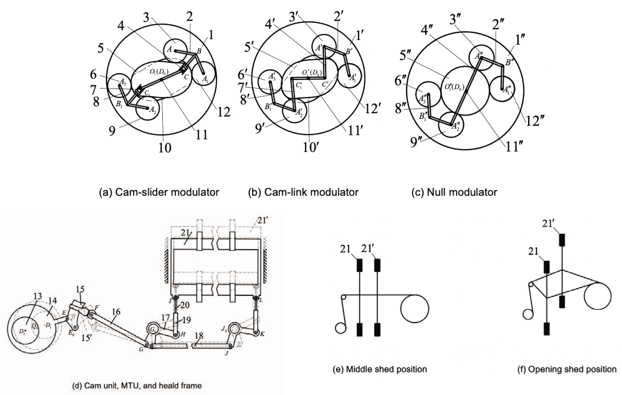
Heald frame motion principle. (a) Cam-slider modulator. (b) Cam-link modulator. (c) Null modulator. (d) Cam unit, motion transmission unit (MTU), and heald frame. (e) Middle shed position. (f) Opening shed position.
The cam-link modulator is similar to the cam-slider modulator. In Figure 1(b), large gear 1′; conjugate cams 5′ and 10′; cam rollers 3′, 6′, 9′, and 12′; cam swing arms 2′ and 8′; links 4′ and 7′; and main shaft 11′ constitute the cam-link modulator. The cam swing arms are fixed on the large gear. When the loom is running, cam swing arms are hinged to the large gear, and the motion is transmitted to cam rollers. The conjugate cams are fixed on the dobby body, so that the four cam rollers move along the main and the auxiliary cam contours of the conjugate cam. The clockwise rotation of follower rollers causes links to move and drive main shaft.
Therefore, the modulator transforms the uniform rotary motion of the weaving machine into a non-uniform rotary motion of the dobby main shaft. The use of conjugate cam and linkages or sliders with precise characteristics and the requirements of heald frame motion principle can be met.
The null modulator is similar to the cam-link modulator. The difference is that the conjugate cam is replaced by a circular one. As it can be seen in Figure 1(c), the null modulator transforms the uniform rotary motion of the weaving machine into the main shaft of the dobby.
Rotary dobby mechanisms are normally built to control 12, 16, 20, 24, 28, and up to 32 heald frames. Thus, the same number of cam units and motion transmission units (MTUs) as heald frames is required. Two groups are taken as an example. Figure 1(d) shows the moving principle of the cam unit and the MTU, where 15 is the first lifting arm and 15′ is the other lifting arm, and 21 is the first heald frame and 21′ is the other heald frame. Eccentric disc cam 13, ring link 14, and lifting arm 15 constitute one of the cam units of the rotary dobby. Point D0 is the central point of the main shaft, which transfers the non-uniform rotary motion generated by the modulator to the main shaft and then to the cam unit. In addition, it performs the reciprocating swing of lifting arm 15(15′). Each heald frame is controlled by a cam unit with a width of only 12 mm. A ratchet placed on the outside of the cam connects it with the driver, and a 180° rotation of the cam produces a lifting or lowering motion. The MTU consists of a four-bar linkage mechanism and a crank-slider mechanism. Lifting arm 15(15′), lifting arm link 16, and swivel arm 17 constitute one of the four-bar linkage mechanism. Heald frame link 19, support link 20, and heald frame 21 constitute the crank slider mechanism and transform the swing motion of the lifting arm 15(15′) into a straight-line motion of the heald frame 21(21′).
Figure 1(e) and (f) illustrates the schematic diagram of the middle shed and the shuttle opening configurations. The heald frame 21(21′) separates warp yarns into two layers, forming an opening for weft insertion.
The warp yarn forms a shed at one revolution of the loom main shaft. The warp yarn motion goes through three stages:
Opening stage: heald frames 21 and 21′ leave the middle shed position and separate up and down until the shed is in its fully open state.
Dwell stage: the weft has enough time to pass through the shed, and heald frames 21 and 21′ need to be stationary for a certain period of time.
Closing stage: heald frames 21 and 21′ return from the fully open position to the middle shed position.
3 Shedding motion mathematical model
3.1 Modulator modeling
Figure 2(a) and (b) shows the schematic diagrams of the cam-slider and cam-link modulators, respectively.
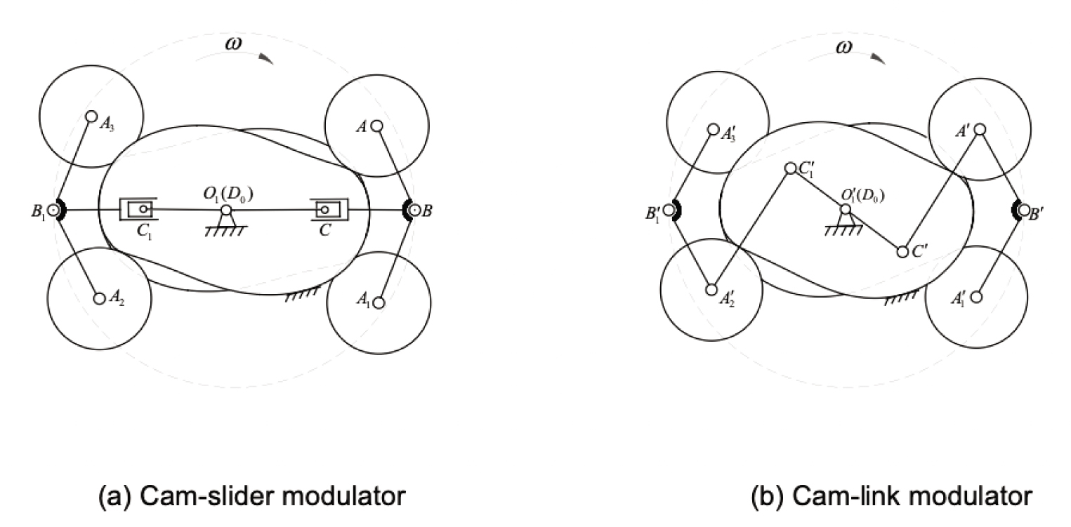
The two modulator types. (a) Cam-slider modulator. (b) Cam-link modulator.
When large gear rotates clockwise at an angular velocity W, the cam rollers are tangent to the conjugate cams. Taking a cam roller as an example, in Figure 2(a), cam swing arm AB is hinged at point B and can rotate around it through the large gear. When engagement takes place, the uniform motion of the large gear is transmitted to the cam swing arm AB . The modulator slider BC is hinged at point C, can rotate around point O1, and develop a rotary motion of the dobby main shaft fixed at point O1. In Figure 2(b), the cam swing arm A′B′ is hinged at point B′ and can rotate around it through the large gear. When engagement takes place, the uniform motion of the large gear is transmitted to the cam swing arm A′B′ through the cam roller. The modulator linkage A′C′ is hinged at point C′, can rotate around point
In order to perform numerical calculations, 200 cam contour points were measured using a coordinate measuring machine. Cubic NURBS curve interpolation was used to construct the conjugate cam contour of the rotary dobby. In Figure 3, the coordinates of the cam profile mapping points are presented.
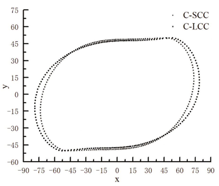
Contour point coordinates. C-SCC: cam contour of the cam-slider. C-LCC: cam contour of the cam-link.
3.1.1 Cam-slider
Figure 4 illustrates the schematic diagram of the cam-slider of the single roller modulator. The radius of the roller is r. Point B on the large gear is centered at point O1 . The trajectory formed by point A is the theoretical cam profile.
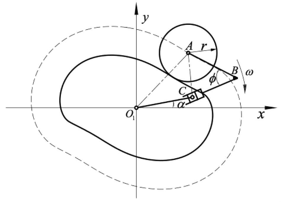
Cam-slider with a single roller.
The theoretical cam curve is described by
Point A (xA, yA) satisfies
Point B (xB, yB) satisfies
From the law of cosines:
From the geometric relationship:
where ω the uniform angular velocity, the angle ϕ, and points A (xA, yA), LAB, LBC, and LAC are known parameters. The angle a can be obtained from Equations (1) to (7).
3.1.2 Cam-link
Figure 5 shows the schematic diagram of the cam-link with a single roller. The radius of the roller is r1. Point B′ on the large gear is centered at point

Cam-link with a single roller.
The theoretical cam curve is described by
Point A′ (xA′, yA′) coordinates satisfy
Point B′ (xB′, yB′) coordinates satisfy
From the geometric relationship:
From the law of cosines:
In addition:
The uniform angular velocity ω, the angle ϕ1, and points A′ (xA′, yA′), LA′B′, LB′C′, and LA′C′ are known parameters. From equations (8) to (13), α1 can be obtained.
3.2 Modeling of the cam unit
Figure 6 shows the schematic diagram of the cam unit of the rotary dobby. The kinematic design and analysis of the cam unit of a rotary dobby can be carried out using the illustrated crank rocker mechanism (D0DEE0). During one revolution of the link D0D, the link E0E swings between its extreme positions. When the link D0D translates to the D0D1 position, the lifting arm 15 is at the upper position and the lifting arm 15′ is at the lower position. Then, the heald frame 21′ reaches the upper shed position, and the heald frame 21 reaches the lower shed position. Otherwise, when the link D0D translates to the D0D2 position, the lifting arm 15 is at the lower position and the lifting arm 15′ is at the upper position, and then, the heald frame 21′ reaches the lower shed position and the heald frame 21 reaches the upper shed position.

Schematic diagram of the cam unit.
The rotation center D0 of the link D0D is the main shaft center point O1(O1′). The D0D and the x axis is in the positive angle φ0, φ0=α, α=α1.
From the geometric relationships and the law of cosines:
Then
where LD0D, LDE, LEE0, and LD0E0 are known parameters.
3.3 MTU modeling
Figure 7 shows the schematic diagram of the MTU. The link E0E is rigidly coupled to the link E0F and the angle β1 around point E0. The positive angle between the link E0F and the x axis is φ4.

Schematic diagram of the motion transmission unit (MTU).
The angular displacement of the link G0G relative to the link E0F can be calculated as follows:
Equation (19) can be written as
Then
where A = a2 + b2, B = −2bc, C = c2 − a2, a = LE0F cosj4 − LE0G0,
The angle φ6 between the link G0G and the x axis can be obtained. The rotational motion of the link G0H is transformed into a straight-line motion of the slider IL through the following geometric relationships:
where φ7=270°−(φ6+β2) is the angle between the link G0H and the y axis, β2 and e are known parameters in the slider crank mechanism (G0HI), φ6 is obtained in the analysis of the four-bar linkage (E0FGG0), and S is the displacement of the heald frame 21(21′).
4 Results and discussion
The parameters of the cam-slider and cam-link modulators are shown in Table 1, and the parameters of the cam unit and the MTU are shown in Table 2.
Modulator parameters
| Cam-slider modulator | Value | Cam-link modulator | Value |
|---|---|---|---|
| r (mm) | 31 | r1 (mm) | 31 |
| LAB (mm) | 47 | LA′B′ (mm) | 47 |
| LO1 C (mm) | 81 | LA′C′ (mm) | 81 |
| ϕ (°) | 60 |
|
56 |
Cam unit and motion transmission unit (MTU) parameters
| Cam unit | Value | MTU | Value |
|---|---|---|---|
| LD0D (mm) | 30 | LFG (mm) | 550 |
| LDE (mm) | 170 | LGG0 (mm) | 150 |
| LEE0 (mm) | 96 | LG0H (mm) | 200 |
| LD0E0 (mm) | 185 | LE0G0 (mm) | 695 |
| LE0F (mm) | 207 | LHI (mm) | 375 |
| β1 (°) | 90 | β2 (°) | 90 |
| – | – | e (mm) | 198 |
A program was developed in Visual Studio 2012 using the data in Tables 1 and 2, and Equations (1) to (21). The rotational speed of the large gear of the main motor was set to 100 rpm. One work cycle of the large gear was calculated. Figure 8 shows the motion characteristics of the cam-slider modulator and the cam-link modulator.
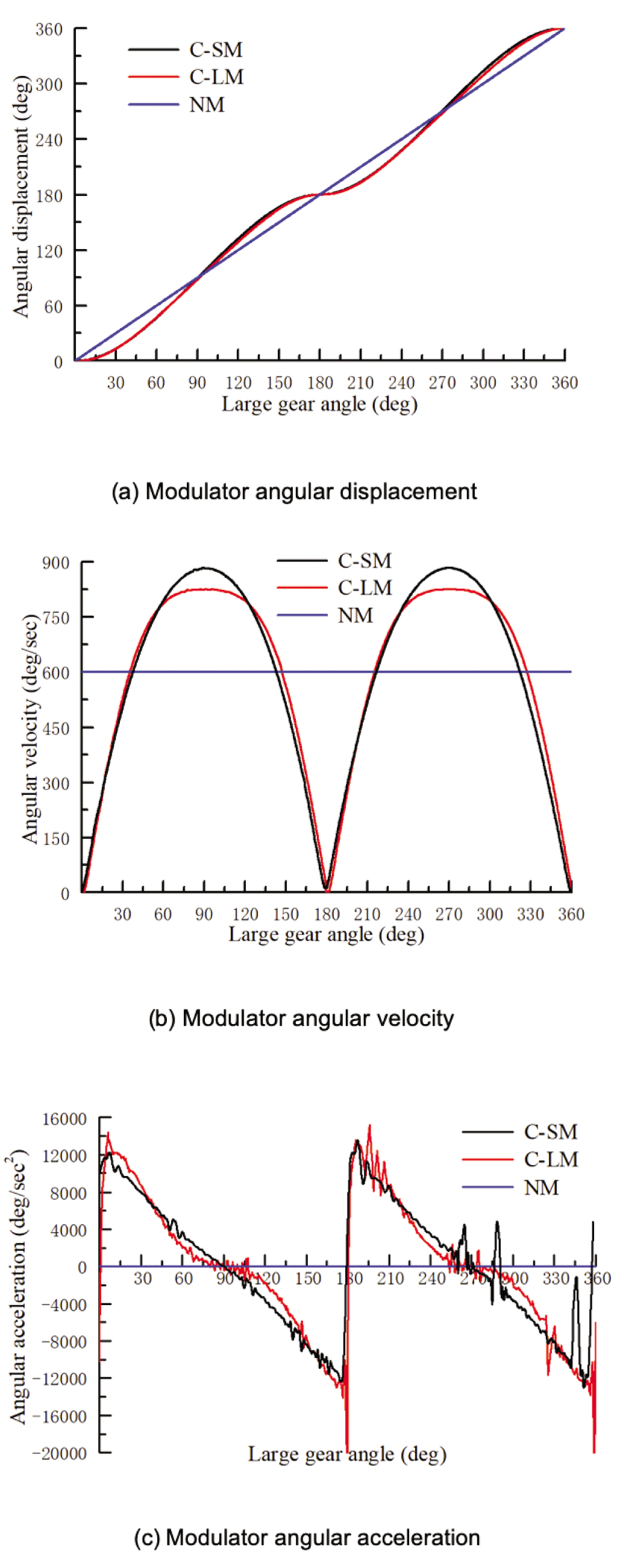
Motion characteristics of the cam-slider modulator (C-SM), cam-link modulator (C-LM), and null modulator (NM). (a) Modulator angular displacement. (b) Modulator angular velocity. (c) Modulator angular acceleration.
As it can be seen in Figure 8(a), the cam-slider modulator and cam-link modulator angular displacement curves are basically consistent. Approximately 10° dobby modulator main shaft double-dwells are formed. Therefore, the modulator transformed the uniform rotary motion of the weaving machine into a non-uniform rotary motion of the dobby main shaft. On the other hand, the null modulator cannot form dwell, and thus, the dobby main shaft performed a uniform rotary motion. Figure 8(b) shows that the maximum angular velocity was higher with the cam-slider modulator than with the cam-link modulator, while the cam-slider modulator angular velocity was about 7% higher than that of the cam-link modulator. The cam-link modulator generated a motion with a longer approximately uniform motion period than the cam-slider modulator. From the angular velocity curves, it can be clearly seen that the cam-link modulator was more stable than the cam-slider modulator. This can be more clearly observed in the modulator angular acceleration curves in Figure 8(c). The surface irregularity of the cam profile is one of the primary sources of vibration noise. The angular acceleration of the cam-link modulator had a gradual period, but the cam-slider modulator did not. This means that the motion characteristics produced by the cam-link modulator were more stable and reliable than those produced by the cam-slider modulator.
Modulator maximum velocity and acceleration comparison
| Type | Velocity (deg/s) | Acceleration (deg/s2) |
|---|---|---|
| Cam-slider | 883 | 12154 |
| Cam-link | 826 | 11778 |
| Difference (%) | 7 | 3 |
The cam unit is the main executive mechanism for controlling the shedding motion of the heald frame. The design of the cam unit determines the output motion characteristics of the lifting arm, thus affecting the shedding motion of the heald frame. Figure 9 demonstrates the motion characteristics of the cam unit’s lifting arms 15 and 15′ generated by the three different modulators. In Figure 9(a), the input motion of the cam unit is a nonuniform rotating motion transmitted by the cam-slider and cam-link modulators, and the output motion is the swing motion of the cam unit’s lifting arm. The cam-slider and cam-link modulators’ angular displacement curves were basically consistent. It can be concluded that the cam-slider and the cam-link modulators can generate a cam motion with an approximately same dwell period. As it was previously mentioned, the null modulator cannot form dwell. This can be more clearly seen in the curves of angular velocity and angular acceleration in Figure 9(b) and (c), respectively.

Motion characteristics of the cam unit 15 driven by the cam-slider modulator (C-SCU 15), cam unit 15′ driven by the cam-slider modulator (C-SCU 15′), cam unit 15 driven by the cam-link modulator (C-LCU 15), cam unit 15′ driven by the cam-link modulator (C-LCU 15′), cam unit 15 driven by the null modulator (NCU 15), and cam unit 15′ driven by the null modulator (NCU 15′). (a) Cam unit’s angular displacement. (b) Cam unit’s angular velocity. (c) Cam unit’s angular acceleration.
In Figure 9(b), it can be seen that the maximum velocities of both the cam lifting arms 15 and 15′ are higher with the cam-slider modulator than with the cam-link modulator. The velocity of the cam driven by the cam-slider modulator was approximately 7% higher in the upper position and 6% higher in the lower position than that driven by the cam-link modulator. Similarly, as it can be observed in Figure 9(c), the maximum acceleration of the cam unit was higher with the cam-slider modulator than with the cam-link modulator, while the acceleration of the cam unit driven by the cam-slider modulator was approximately 10% higher than that driven by the cam-link modulator in both the upper and lower positions. A detailed comparison is given in Tables 4 and 5. The results indicated that the motion curves of the cam unit have continuous velocity and acceleration. Therefore, the cam-link modulator should be used to prevent impact stresses and noise in the structure.
Cam units’ maximum velocity comparison (deg/s)
| Type | Cam unit 15 | Cam unit 15′ | ||
|---|---|---|---|---|
| Upper | Lower | Upper | Lower | |
| Cam-slider | 275 | 289 | 275 | 289 |
| Cam-link | 258 | 271 | 258 | 271 |
| Difference (%) | 6 | 7 | 6 | 7 |
Cam units’ maximum acceleration comparison (deg/s2)
| Type | Cam unit 15 | Cam unit 15′ | ||
|---|---|---|---|---|
| Upper | Lower | Upper | Lower | |
| Cam-slider | 3625 | 3688 | 3625 | 3688 |
| Cam-link | 3300 | 3348 | 3300 | 3348 |
| Difference (%) | 10 | 10 | 10 | 10 |
Figure 10 demonstrates the motion characteristics of the heald frames 21 and 21′ generated by the three different modulators. The motion characteristics of the heald frame are similar to those of the lifting arm. The motion transmission mechanism does not affect significantly the motion characteristics of the heald frame.

Motion characteristics of the heald frame 21 driven by the cam-slider modulator (C-SHF 21), heald frame 21′ driven by the cam-slider modulator (C-SHF 21′), heald frame 21 driven by the cam-link modulator (C-LHF 21), heald frame 21′ driven by the cam-link modulator (C-LHF 21′), heald frame 21 driven by the null modulator (NHF 21), and heald frame 21′ driven by the null modulator (NHF 21′). (a) Heald frame displacement. (b) Heald frame velocity. (c) Heald frame acceleration.
In Figure 10(a), it can be concluded that the cam-slider modulator and the cam-link modulator generate a heald frame motion with an approximately same dwell period. However, it may be recalled from Figure 6 that the cam unit is a crank-rocker mechanism without snapback characteristics. The motion characteristics of heald frames 21 and 21′ are not exactly the same. The heald frame 21 has a longer approximate dwell than heald frame 21′ at both the lower and upper shed positions. At a displacement of 46 mm, the heald frames 21 and 21′ reach the middle shed position and complete the shedding motion. Since the null modulator’s main shaft performs a uniform circular motion where no heald frame dwell is obtained, the actual working conditions of the loom are not met. This result indicated that the dwell of the heald frame is controlled by the cam-slider or the cam-link modulator of the rotary dobby.
On the other hand, Figure 10(b) and (c) shows that the maximum velocities of the heald frames 21 and 21′ with the cam-slider modulator were higher than those with the cam-link modulator. The velocity of heald frames 21 and 21′ driven by the cam-slider modulator was approximately 7% higher in the upper position and 6% higher in the lower position than that driven by the cam-link modulator. The maximum acceleration of heald frames 21 and 21′ with the cam-slider modulator was higher than that with the cam-link modulator. The acceleration of heald frame driven by the cam-slider modulator was approximately 9% higher in the upper position and 5% higher in the lower position than that driven by the cam-link modulator. A detailed comparison is given in Tables 6 and 7. The motion characteristics of the heald frame require the velocity of the heald frame to be stable and avoid sudden changes. The warp should move slowly in its tense state and faster in the relaxed state. Therefore, the motion of the heald frame should be slower near the fully open shed position and faster near the middle shed position. The transition of the heald frame from stationary to moving and from moving to stationary should be slow and the acceleration should be stable, in order to avoid causing vibration of the heald frame. Owing to this, the cam contour in the modulator was obtained by mapping; there were measurement and fitting errors. However, by comparing the curves in Figure 10(b) and (c), it can be clearly seen that the velocity and acceleration of heald frames 21 and 21′ produced by the cam-link modulator were more stable compared to those produced by the cam-slider modulator.
Heald frame maximum velocity comparison (m/s)
| Type | Heald frame 21 | Heald frame 21′ | ||
|---|---|---|---|---|
| Upper | Lower | Upper | Lower | |
| Cam-slider | 0.858 | 0.927 | 0.858 | 0.927 |
| Cam-link | 0.802 | 0.873 | 0.802 | 0.873 |
| Difference (%) | 7 | 6 | 7 | 6 |
Heald frame maximum acceleration comparison (m/s2)
| Type | Heald frame 21 | Heald frame 21′ | ||
|---|---|---|---|---|
| Upper | Lower | Upper | Lower | |
| Cam-slider | 10.217 | 12.846 | 10.217 | 12.846 |
| Cam-link | 9.365 | 12.242 | 9.365 | 12.242 |
| Difference (%) | 9 | 5 | 9 | 5 |
When rotary dobby with this cam-link modulator is applied to different looms or different fabrics, especially with different speeds, further analysis to the characteristics of the dynamics of the heald frame is required.
5 Conclusions
The displacement, velocity, and acceleration curves of the modulator main shaft, cam unit, and heald frame with a cam-slider or a cam-link modulator were obtained by numerical calculations based on the established mathematical model. At the same time, the motion characteristics of the cam unit and heald frame with the null modulator were obtained. Based on the above analysis, it can be concluded that the dwell of the heald frame is controlled by the modulator of the rotary dobby. The motion characteristics of the heald frame are similar to those of the cam unit. The MTU enlarges the swing motion of the cam unit and transfers it to the heald frame, producing the up and down motion of the heald frame.
The comparison of the displacement, velocity, and acceleration curves of the modulator main shaft, cam unit, and heald frame with a cam-slider or a cam-link modulator indicated that the motion characteristics of the modulator and heald frame produced by the cam-link modulator are more stable than those produced by the cam-slider modulator. This difference is more apparent when comparing the velocity and acceleration curves. The heald frame driven by the rotary dobby with the cam-link is more stable and reliable than that with the cam-slider modulator.
Acknowledgment
The authors disclosed receipt of the following financial support for the research, authorship, and/or publication of this article: This research was supported by the National Key R&D Program of China (2016YFB1102003 and 2017YFB1104202).
References
[1] Eren, R., Özkan, G., Turhan, Y. (2008). Kinematics of rotary dobby and analysis of heald frame motion in weaving process. Textile Research Journal, 78, 1070–1079.10.1177/0040517507083549Search in Google Scholar
[2] Adanur, S. (2000). Handbook of weaving. CRC Press (U.S.A.), 110–113.Search in Google Scholar
[3] Eren, R., Özkan, G., Karahan, M. (2005). Comparison of Heald frame motion generated by rotary dobby and crank & cam shedding motions. Fibres & Textiles in Eastern Europe, 13(4), 78–83.Search in Google Scholar
[4] Korolev, P. A., Lohmanov, V. N. (2011). Kinematics of connections of the shedding mechanism of a circular loom TKP-110-U. Lzvestiya Vysshikh Uchebnykh Zavedenii, Seriya Teknologiya, 4, 116–119.Search in Google Scholar
[5] Sadettin, K., Taylan, D. M., Ali, K. (2010). Cam motion tuning of shedding mechanism for vibration reduction of heald frame. Gazi University Journal of Science, 23(2), 227–232.Search in Google Scholar
[6] Abdullah, G., Hasçelik, B., Palamutcu, S., Soydan, A. S. (2010). Synthesis work about driving mechanism of a novel rotary dobby mechanism. Tekstil ve Konfeksiyon, 20(3), 218–224.Search in Google Scholar
[7] Liu, Z. X. (1985). Structure and motion analysis of rotary dobby. Wool Textile Journal, 1, 29–38.Search in Google Scholar
[8] Guo, Y. Y., Chen, R. Q. (2003). A new type of microprocessor controlled positive dobby. Indian Journal of Fiber and Textile Research, 28, 275–280.Search in Google Scholar
[9] Gao, D. N., Shen, Y., Liu, C. L. (2012). The design of election comprehensive conjugate cam of GT421 dobby. Advance Textile Technology, 20(1), 27–31.Search in Google Scholar
[10] Gao, D. N., Shen, Y., Liu, C. L. (2012). Dynamic simulation of mechanism of GT421 dobby based on ADAMS. Journal of Textile Research, 33(8), 119–123.Search in Google Scholar
[11] Mrazek, J. (1992). Theoretical analysis of dynamics four-bar beat up mechanisms of a loom. Mechanism and Machine Theory, 27(3), 331–341.10.1016/0094-114X(92)90023-BSearch in Google Scholar
[12] Jin, G. G., Wei, X. Y., Wei, Z., Chang, B., Zhang, X. (2018). Dynamic analysis and optimization of rotary dobby lifting comprehensive mechanism. Journal of Textile Research, 39(9), 160–168.Search in Google Scholar
[13] Bílek, M., Mrazek, J. (1998). Dynamic stress of Heald shaft of weaving looms. Fibres and Textiles, 3, 131–134.Search in Google Scholar
[14] Bílek, M., Skřivánek, J. (2013). Mathematical modeling of the system shedding motion - Heald - warp. AUTEX Research Journal, 13(2), 42–46.10.2478/v10304-012-0022-8Search in Google Scholar
[15] Zhang, Y. H., Gou, X. F., Chen, X. F., et al. Redesign of conjugate cam of rotation variable speed mechanism of electronic dobby. Journal of Mechanical Transmission 2018; 42(4): 57–61.Search in Google Scholar
[16] Anon. (1983). Rotary dobby-the efficient shed forming mechanism for modern weaving machines. International Textile Bulletin, Fabric Forming (Eng. Ed.), 66, 45–46.Search in Google Scholar
[17] Marks, R., Robinson, A. T. C. (1976). Principles of weaving. London: The Textile Institute, Manchester, 59–72.Search in Google Scholar
[18] Guha, A., Amarnath, C., Kurien, I., Talukdar, M. K. (2009). Linkage driven dobby with dwell. Textile Research Journal, 79(9), 804–809.10.1177/0040517507087673Search in Google Scholar
[19] Chiu, H. C., Lin, T. R. (2005). A novel reverse measurement and manufacturing of conjugate cams in a diesel engine. International Journal of Advanced Manufacturing Technology, 26(1), 41–46.10.1007/s00170-003-1984-4Search in Google Scholar
[20] Wang, Q. X., Yuan, Y. H. (2013). Analysis and design of Heald selecting conjugate cam mechanism of HQ3620 rotary electronic dobby. Advanced Textile Technology, 21(6), 9–12.Search in Google Scholar
[21] Shen, Y., Liu, C. L., Gao, D. N. (2012). Design and application of a combined mechanism with conjugate cam and slider rocker. Machine Design and Research, 28(4), 22–25.Search in Google Scholar
[22] Chen, M., Ma, F. X. (1998). A positive dobby for weaving converted from a negative one (Staubli 2500). Journal of China Textile University (Eng. Ed.), 15(2), 39–41.Search in Google Scholar
[23] Singh, Y. P., Kohli, D. (1981). Synthesis of cam-link mechanisms for exact path generation. Mechanism and Machine Theory, 16(4), 447–457.10.1016/0094-114X(81)90017-3Search in Google Scholar
[24] Erdman, A. G., Sandor, G. N., Kota, S. (2001). Mechanism design: Analysis and synthesis. Prentice-Hall (Englewood Cliffs), 1, 426–435.Search in Google Scholar
[25] Ye, Z., Smith, M. R. (2005). Design of a combined cam-linkage mechanism with an oscillating roller follower by an analytical method. Proceedings of the Institution of Mechanical Engineers-Part C: Journal of Mechanical Engineering Science, 219(4), 419–427.10.1243/095440605X16884Search in Google Scholar
[26] Mundo, D., Danieli, G. A., Yan, H. S. (2006). Kinematic optimization of mechanical presses by optimal synthesis of cam-integrated linkages. Transactions of the Canadian Society for Mechanical Engineering, 30(4), 519–532.10.1139/tcsme-2006-0033Search in Google Scholar
[27] Mundo, D., Liu, J. Y., Yan, H. S. (2006). Optimal synthesis of cam-linkage mechanisms for precise path generation. Journal of Mechanical Design, 128(6), 1253–1260.10.1115/1.2337317Search in Google Scholar
[28] Wang, Y., Chen, J. N., Zhao, X., Zhang, G., Yu, B. (2013). Study on cam profile’s expression method and its applications based on NURBS curves. China Mechanical Engineering, 24(10), 1375–1380.Search in Google Scholar
[29] Sun, H., Chen, Z. M., Ge, W. J. (2006). Theory of machines and mechanisms. (7th ed.) Higher Education Press (Beijing), 117–120.Search in Google Scholar
© 2021 Honghuan Yin et al., published by Sciendo
This work is licensed under the Creative Commons Attribution 4.0 International License.
Articles in the same Issue
- Investigation of Textile Heating Element in Simulated Wearing Conditions
- The Influence of Brand on Consumer Quality Assessment of Clothes: A Case Study of the Polish Market
- Limitations of the CAD-CAM System in the Process of Weaving
- Thermal Protective Performance of Firefighters’ Clothing Under Low-Intensity Radiation Heat Exposure
- The Eco-Modification of Textiles Using Enzymatic Pretreatment and New Organic UV Absorbers
- Development of Ergonomically Designed Functional Bra for Women with Hemiplegia
- Polish Textile and Apparel Industry: Global Supply Chain Management Perspective
- Yarn Damage Evaluation in the Flat Knitting Process
- Surface Characteristics of Seersucker Woven Fabrics
- Structural Damage Characteristics of a Layer-to-Layer 3-D Angle-Interlock Woven Composite Subjected to Drop-Weight Impact
- Changeover Process Assessment of Warp-Knitting Let-Off Equipped with Multispeed Electronic Let-Off System
- Thermal Analysis of Heating–Cooling Mat of Textile Incubator for Infants
- Kinematic Comparison of a Heald Frame Driven by A Rotary Dobby with A Cam-Slider, A Cam-Link and A Null Modulator
- Durability Assessment of Composite Structural Element Reinforced with Fabric due to Delamination
- Analysis of Basis Weight Uniformity Indexes for the Evaluation of Fiber Injection Molded Nonwoven Preforms