Two new POM-based compounds containing a linear tri-nuclear copper(II) cluster and an infinite copper(II) chain, respectively
-
Ai-xiang Tian
 ,
Ya-li Ning
,
Ya-li Ning

Abstract
Using the pendent organic ligand 1-butyl-1H-(1,3,4)triazole (btz), two new polyoxometalate (POM)-based compounds, [Cu3(btz)6(H2O)4(H3P2W18O62)2]·6H2O (1) and [Cu2(btz)(tz)(H2O)2(SiMo12O40)]·5H2O (2) (tz=1H-(1,3,4)triazole), have been synthesized under hydrothermal conditions. In compound 1, three CuII ions are fused by six btz ligands to form a linear tri-nuclear CuII cluster, with water as bridging molecules. Two Wells-Dawson anions offer two terminal O atoms to link two apical CuII atoms of this tri-nuclear cluster. In compound 2, the btz and tz molecules connect CuII ions to construct an infinite CuII chain still with water molecules as bridges. The adjacent chains are linked by one type of POM anions to build a 2D grid-like layer. Considering the long-range coordinative Cu–O bonds, the other types of POM anions connect adjacent layers to form a 3D framework. The electrochemical and photocatalytic properties of compounds 1 and 2 were also studied.
1 Introduction
In recent years, polyoxometalates (POMs), as inorganic metal oxide clusters, have attracted much attention as they own diverse structures [1], [2], [3] and applications in the areas of catalysis, magnetism, medicine, and electrochromism [4], [5], [6]. Owing to the abundant bridging and terminal oxygen atoms, POMs are always viewed as good inorganic candidates to link metal–organic complexes (MOCs) [7], [8], [9], aiming to broaden the scope of structures and property in the POM field. Among various POM types, Wells-Dawson and Keggin are classical anions and are usually used as inorganic ligands to connect MOCs. A series of Wells-Dawson- and Keggin-based organic–inorganic hybrid compounds have already been synthesized and reported [10], [11]. Thus, using Wells-Dawson and Keggin anions as inorganic ligands is an effective synthetic strategy to coordinate with MOCs, in order to obtain structures with novel topologies and properties.
In POM-based organic–inorganic hybrid compounds, nitrogen donor-containing ligands are commonly used because of their strong coordination ability. In our previous work, we used flexible bis(1,2,4-triazole) ligands as organic moieties, such as 1,3-bis(1,2,4-triazole-1-y1)propane, 1,4-bis(1,2,4-triazole-1-y1)butane, and 1,6-bis(1,2,4-triazole-1-y1)hexane [12], [13], [14], [15]. However, the two N donors in this series are discrete, only in favor of forming highly connective and multi-dimensional frameworks. In this work, we change the strategy to choose an isomeric derivative 1,3,4-triazole to construct POM structures, namely 1-butyl-1H-(1,3,4)triazole (btz). The two apical N donors of btz can induce multi-nuclear clusters with ease [16]. Though btz contains only one 1,3,4-triazole group, we want to explore whether this simple ligand can still induce novel structures.
Thus, in this work we introduced Wells-Dawson and Keggin anions to the CuII–btz system, and fortunately, we obtained two POM-based compounds, namely, [Cu3(btz)6(H2O)4(H3P2W18O62)2]·6H2O (1) and [Cu2(btz)(tz)(H2O)2(SiMo12O40)]·5H2O (2) (tz=1H-(1,3,4)triazole). We also studied the electrochemical and photocatalytic properties of these two compounds.
2 Results and discussion
2.1 Structure description of 1 and 2
2.1.1 [Cu3(btz)6(H2O)4(H3P2W18O62)2]·6H2O (1)
A single crystal X-ray diffraction study has revealed that compound 1 incorporates three CuII ions, six btz ligands, two [P2W18O62]6− anions (abbreviated to P2W18), and four coordinated and six crystal water molecules (Fig. 1). The valence sum calculations [17] show that all the W atoms are in the +VI oxidation states and all the Cu atoms are in the +II oxidation states. In order to balance the charge, six protons have been added to the formula.
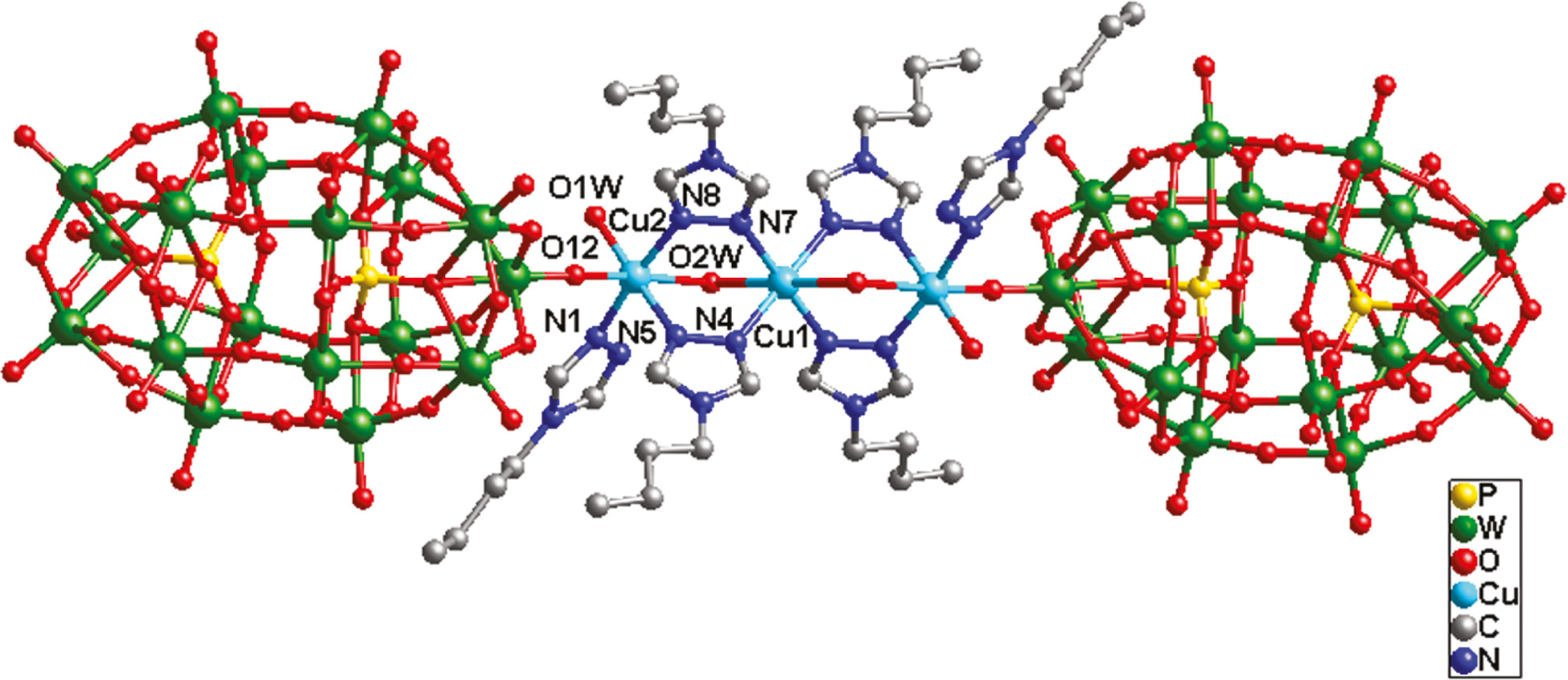
Ball-and-stick view of the centrosymmetric basic molecular unit of 1. The hydrogen atoms and crystal water molecules are omitted for clarity.
In compound 1, there are two crystallographically independent six-coordinated CuII ions, both showing an octahedral coordination geometry. The Cu1 ion is coordinated by four N donors (two N4 and two N7) from four btz ligands and two O2W molecules, whereas the Cu2 ion is coordinated by three N donors (N1, N5, and N8) from three btz ligands, one O12 atom from one P2W18 anion and two water molecules (O1W and O2W). The Cu–N distances are in the range of 1.97(2)–2.007(16) Å, whereas the Cu–O bonds are from 1.93(8) to 2.472(19) Å.
In 1 there exists a linear tri-nuclear CuII cluster, in which three CuII ions are fused by six btz ligands. The btz molecule offers its two apical successive N donors to link two CuII ions. The water molecule O2W acts as a bridging factor to further strengthen this cluster. Two P2W18 anions provide two terminal O12 atoms to connect two apical Cu2 atoms of this tri-nuclear cluster, preventing a dimensional extension (Fig. 2a). Namely, two P2W18 anions cover the linear tri-nuclear CuII cluster, just like a POM “triple-decker” (Fig. 1). Between adjacent POM “triple-decker”, there are several hydrogen bonding interactions inducing a supramolecular 1D chain of 1, such as O34···O2W=2.73 Å (Fig. 3).
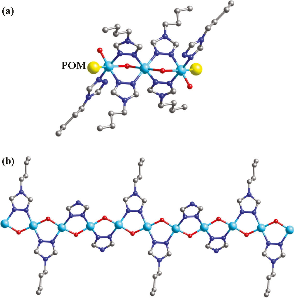
(a) The linear tri-nuclear cluster in compound 1. Two P2W18 anions linked CuII ions are symbolized as yellow spheres; (b) infinite CuII chain in the crystal structure of 2.
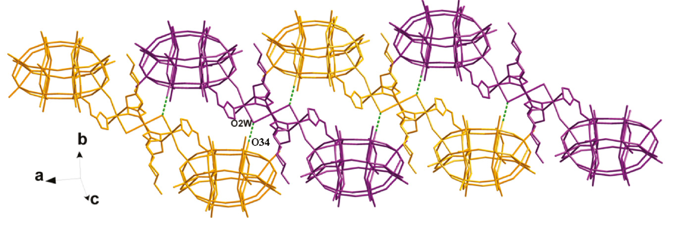
Supramolecular chain formation in the crystal structure of 1 formed by hydrogen bonding interactions (O34···O2W=2.79 Å). The molecular units depicted in Fig. 1 are shown here with different colors.
2.1.2 [Cu2(btz)(tz)(H2O)2(SiMo12O40)]·5H2O (2)
A single crystal X-ray diffraction analysis has shown that compound 2 consists of two CuII ions, one btz and one tz ligands, one [SiMo12O40]4− anion (abbreviated to SiMo12), two coordinated and five crystal water molecules (Fig. 4). The valence sum calculations [17] show that all the Mo atoms are in the +VI oxidation states and all the Cu atoms are in the +II oxidation states. In compound 2, the butyl “tail” –(CH2)3CH3 of some btz molecules was lost to produce a tz ligand, which also has been observed in previous reports using similar ligands [18], [19]. Thus, in 2, the btz and tz molecules cooperate to modify the connectivity of the Keggin anions.
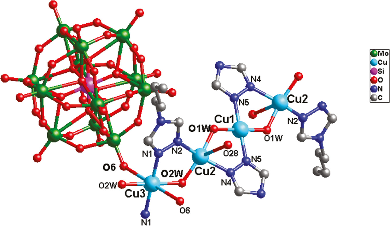
Ball-and-stick view of the basic molecular unit of 2. The hydrogen atoms and crystal water molecules are omitted for clarity.
In compound 2, there are three crystallographically independent CuII ions. The Cu1 ion is four-coordinated by two N5 atoms from two tz ligands and two O1W, showing a square planar coordination geometry. Considering the long-range coordinative Cu2–O28 bonds (2.868 Å), the Cu2 ion is five-coordinated by two N atoms (N2 and N4) from a btz and a tz ligand, respectively, two water molecules (O1W and O2W), and one O28 from one SiMo12 anion, exhibiting a distorted tetragonal pyramidal geometry. The Cu3 ion exhibits an octahedral geometry, coordinated by two N1 atoms from two btz ligands, two O6 from two SiMo12 anions, and two O2W. The Cu–O bonds are in the range 1.874(8)–2.86(8) Å and the Cu–N bonds are from 1.97(10) to 1.988(9) Å.
Both the btz and tz molecules in 2 provide two successive N atoms to link CuII ions, inducing an infinite CuII chain with water molecules as bridges. The btz and tz ligands are attached to this chain up and down alternately (Fig. 2b). In compound 2, there are two types of SiMo12 anions: Si1- and Si2-containing anions. Each Si1-containing anion provides two terminal O6 atoms to fuse Cu3 atoms of adjacent infinite CuII chains. Thus, a grid-like layer of 2 is formed (Fig. 5). Furthermore, considering the long-range coordinative Cu2–O28 bonds (2.868 Å), the Si2-containing anion can supply two terminal O28 atoms to connect adjacent layers. So a 3D framework is constructed (Fig. 6). In the crystal structure of 2, there exist large voids of about 324 Å3, which may be important for potential applications of this material.
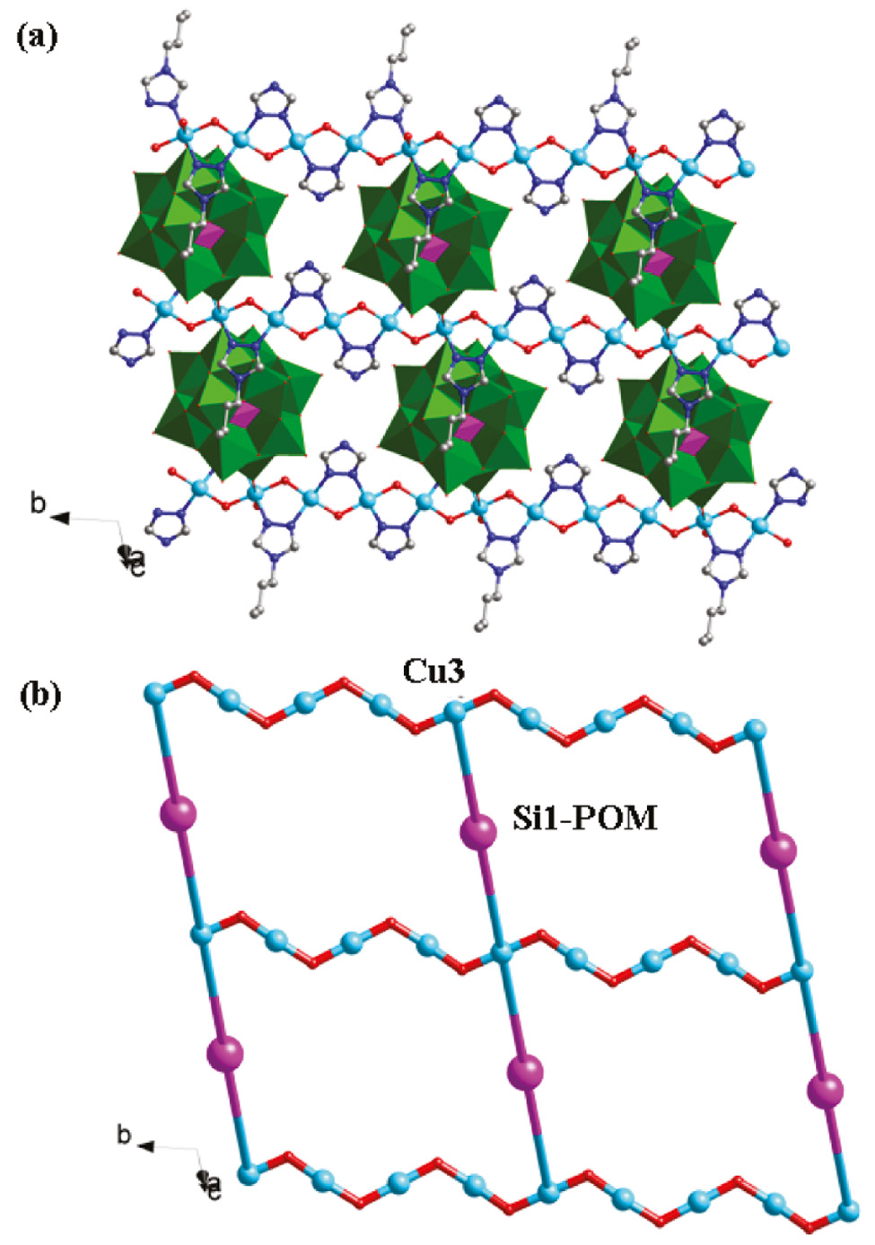
The grid-like layer (a) and its schematic view (b) of compound 2 with Si1-containing anions as pillars.
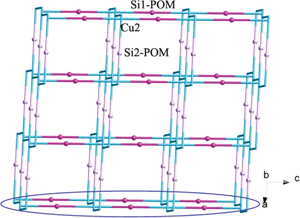
The 3D framework of compound 2 with Si2-containing anions as linkers.
2.2 FT-IR spectra
Figure S1 (Supplementary Information) shows the IR spectra of compounds 1 and 2. The bands at 1093, 954, 906, and 793 cm−1 for 1 are ascribed to the modes of ν(P–O), ν(W–Od), and ν(W–Ob/c–W), respectively. In the spectrum of 2, the characteristic bands at 1089, 968, 906 and 790 cm−1 are attributed to ν(Si–O), ν(Mo–Od), and ν(Mo–Ob/c–Mo), respectively. Furthermore, the bands in the regions of 1614–1214 cm−1 for 1 and 1606–1227 cm−1 for 2 are attributed to the btz and tz ligands.
2.3 Photocatalytic activity
Recently, the POM-based compounds have usually been used as photocatalysts to degrade organic dyes [20]. In this work, we also studied the photocatalytic activities of compounds 1 and 2 to degrade methylene blue (MB) and rhodamine B (RhB) solution under UV irradiation. The process of photocatalysis is as follows: 100 mg of compound 1 or 2 was suspended in 0.02 mmol L−1 MB or RhB aqueous solution 250 mL. The suspension was magnetically stirred for about 10 min to ensure the equilibrium in the dark. In the continued stirring process, the solution was exposed to UV irradiation from an Hg lamp. Every 30 min, 5.0 mL samples were taken out for analysis by UV/Vis spectroscopy. It can be clearly observed from Fig. 7 that after 120 min the conversions of MB are 45% for 1 and 48% for 2. Figure 8 shows the photocatalytic degradation of RhB and the conversions are 33% for 1 and 35% for 2.
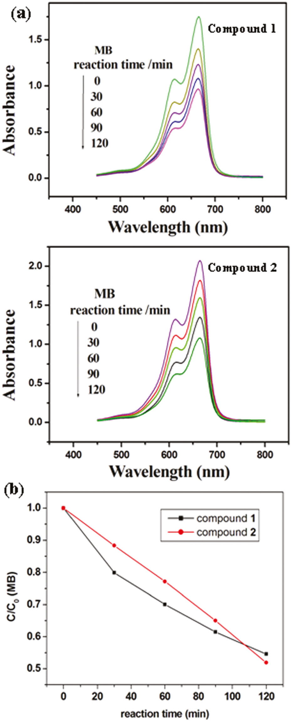
(a) Absorption spectra of the MB solution during the decomposition reaction under UV irradiation with compounds 1 and 2 as catalysts; (b) photocatalytic decomposition rates of the MB solution under UV irradiation with the use of 1 and 2.
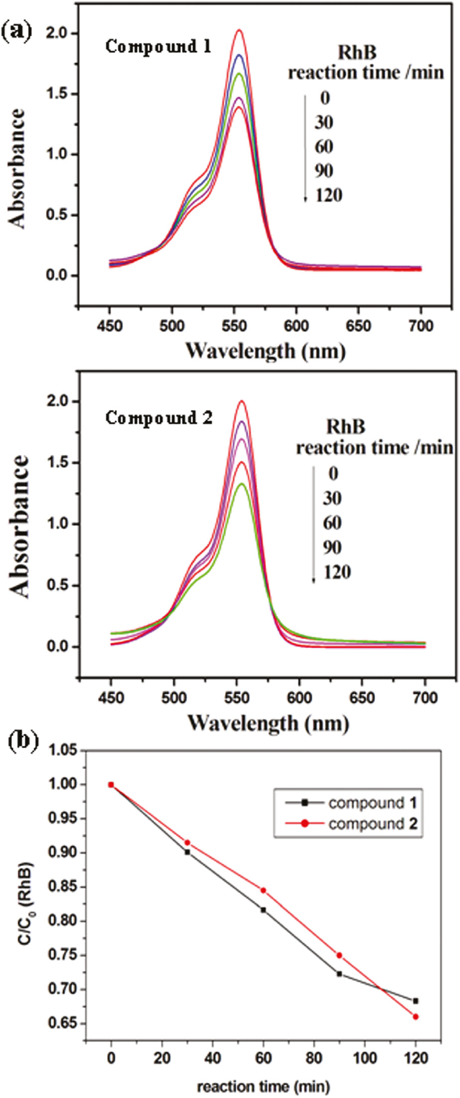
(a) Absorption spectra of the RhB solution during the decomposition reaction under UV irradiation with compounds 1 and 2 as catalysts; (b) photocatalytic decomposition rates of the RhB solution under UV irradiation with the use of 1 and 2.
2.4 Voltammetric behavior and electrocatalytic activity
In this work, we studied the electrochemical properties of 1- and 2-CPEs (1/2 bulk-modified CPE; CPE=carbon paste electrode). The cyclic voltammograms for 1- and 2-CPEs are presented in Fig. 9 for 0.1 m H2SO4+0.5 m Na2SO4 aqueous solutions at different scan rates. In the potential range of +400 to −850 mV for 1-CPE, three reversible redox peaks II-II′, III-III′, and IV-IV′ are observed, respectively, with the half-wave potentials E1/2=(Epa+Epc)/2 at –166 (I-I′), −478 (II-II′), −724 (III-III′) mV (scan rate: 80 mV·s−1). These three redox peaks for 1-CPE should be ascribed to three consecutive two-electron processes of P2W18 [12], [21]. Moreover, there also exists one irreversible anodic peak I′ with the potential of +84 mV, which is assigned to the oxidation of the copper centers [12]. The 2-CPE shows three reversible redox peaks I-I′, II-II′, and III-III′ in the potential range of +600 to −200 mV, corresponding to three consecutive two-electron processes of SiMo12 anions [22]. The half-wave potentials are at +229 (I-I′), +100 (II-II′), and −89 (III-III′) mV (scan rate: 80 mV·s−1). With the scan rates increasing from 20 to 500 mV·s−1, the peak potentials for 1- and 2-CPEs change gradually: the cathodic peak potentials are shifted toward the negative direction, whereas the corresponding anodic peak potentials are shifted to the positive direction.
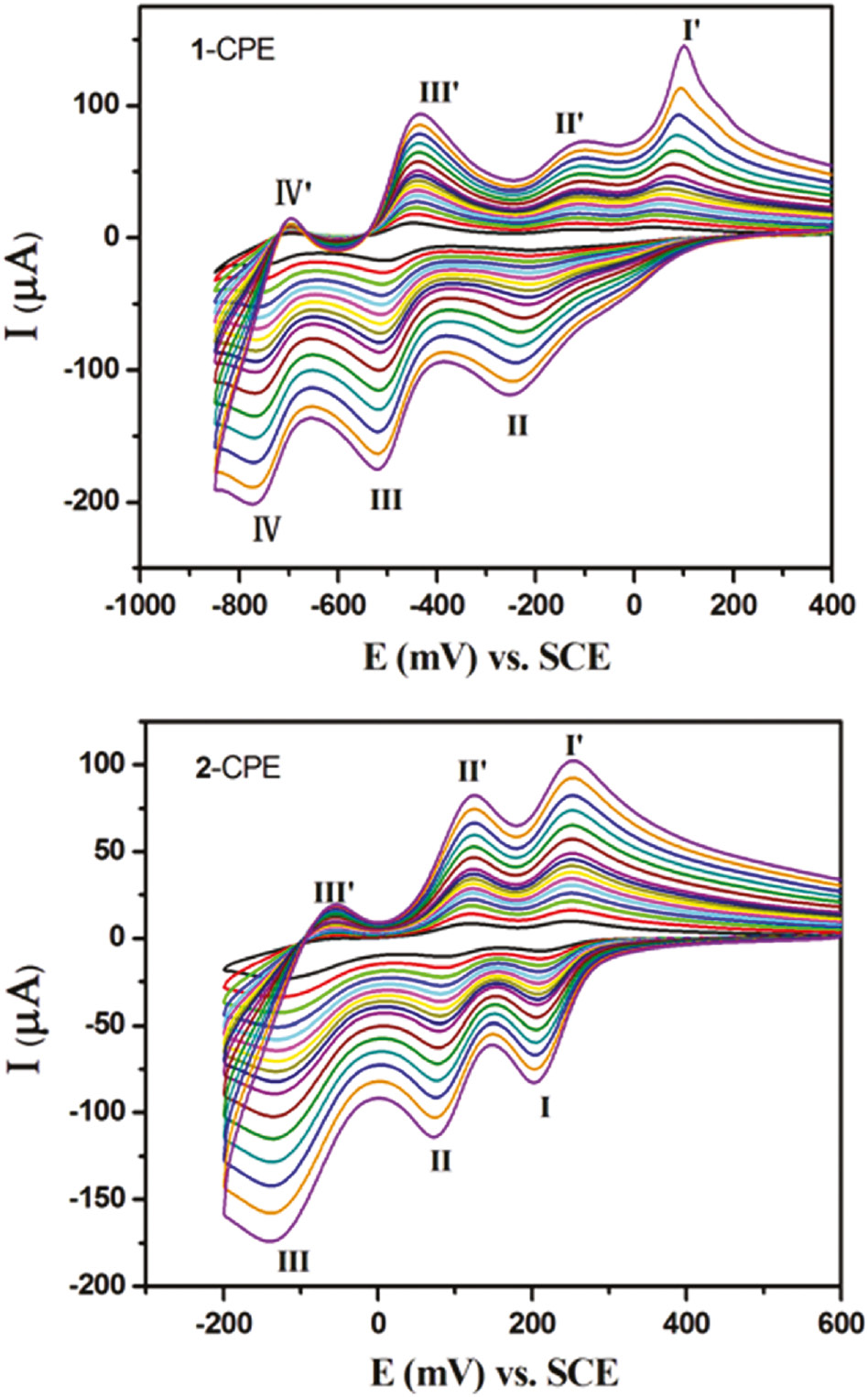
The cyclic voltammograms of the 1- and 2-CPEs in 0.1 m H2SO4+0.5 m Na2SO4 aqueous solution at different scan rates (from inner to outer: 20, 40, 60, 80, 100, 120, 140, 160, 180, 200, 250, 300, 350, 400, 450, and 500 mV·s−1, respectively).
The electrocatalytic reduction of nitrite by 1- and 2-CPEs in 0.1 m H2SO4+0.5 m Na2SO4 aqueous solutions is shown in Fig. 10a. With the addition of nitrite gradually, all the reduced species of P2W18 in 1-CPE and SiMo12 in 2-CPE present electrocatalytic activity for the reduction of nitrite. We also studied the electrocatalytic reduction of bromate by these CPEs (Fig. 10b). With the addition of bromate, the first redox peak remains almost unchanged, showing that only four- and six-electron-reduced species of P2W18 in 1-CPE and SiMo12 in 2-CPE present electrocatalytic activity for the reduction of bromate. It was also noted that the six-electron-reduced species presented the largest catalytic activity.
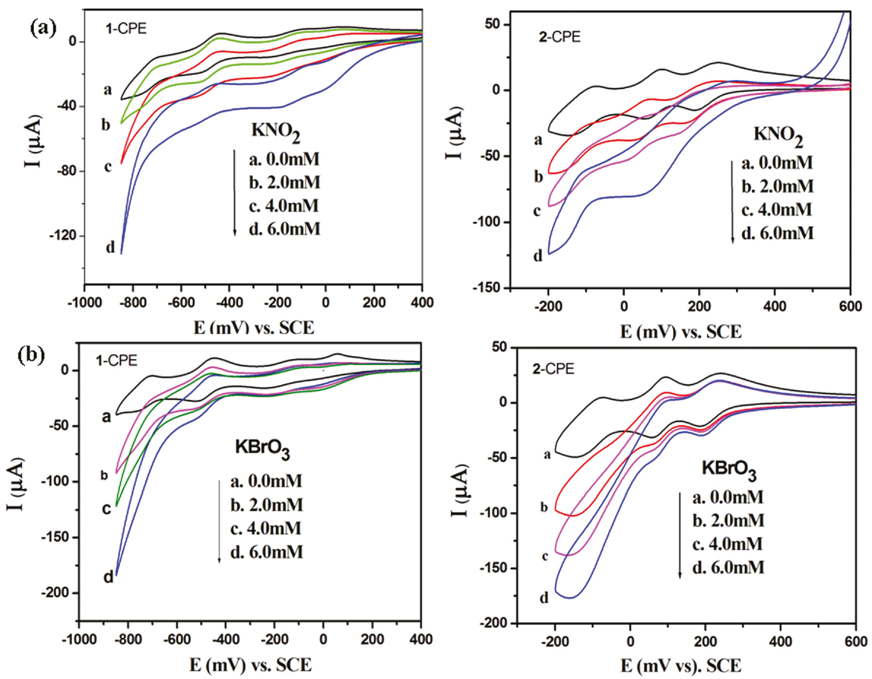
Cyclic voltammograms of the 1- and 2-CPEs in 0.1 m H2SO4+0.5 m Na2SO4 aqueous solution containing KNO2 (a) and KBrO3 (b). Scan rate: 100 mV·s−1.
3 Conclusions
In summary, by using btz ligands, we have obtained two new compounds based on Wells-Dawson and Keggin anions, respectively. The two successive N donors of btz induce a linear tri-nuclear CuII cluster in 1 and an infinite CuII chain in compound 2. Compound 1 shows a “triple-decker” structure with the tri-nuclear cluster clamped by two Wells-Dawson anions. Compound 2 is a 3D framework with infinite CuII chains linked by Keggin anions. Further study on other ligands to build multi-nuclear clusters is underway.
4 Experimental section
4.1 Materials and methods
All reagents and solvents for the syntheses were purchased from commercial sources and used as received without further purification. Elemental analyses (C, H, and N) were carried out with a Perkin-Elmer 2400 CHN elemental analyzer. The FT-IR spectra were taken on Alpha Centaurt FT-IR spectrometer in the 400–4000 cm−1 region (KBr pellets). Electrochemical measurements were performed with a CHI 440 electrochemical workstation. A conventional three-electrode system was used, with modified CPEs as the working electrodes. A saturated calomel electrode was used as a reference electrode, and a Pt wire as a counter electrode. UV/Vis absorption spectra were obtained using an SP-1901 UV/Vis spectrophotometer.
4.2 Synthesis
4.2.1 [Cu3(btz)6(H2O)4(H3P2W18O62)2]·6H2O (1)
A mixture of Cu(CH3COO)2·2H2O (0.064 g, 0.3 mmol), K6P2W18O62 (0.2 g, 0.04 mmol), and btz (0.031 g, 0.25 mmol) was dissolved in 10 mL of distilled water. The pH of the mixture was adjusted with 1 m HCl solution to 4.4 and the solution then sealed into a 20 mL Teflon-lined autoclave. After heating for 3 days at 150°C, the reactor was slowly cooled to room temperature. Green block crystals were filtered and washed with distilled water (40% yield based on W). – Anal. for C36H92Cu3N18O134P4W36 (9854): calcd. C 4.39, H 0.94, N 2.56; found C 4.28, H 0.85, N 2.45%. – IR data (KBr pellet, cm−1): 3490(s), 3120(w), 1614(s), 1567(w), 1490(w), 1454(w), 1397(m), 1254(w), 1214(m), 1151(w), 1093(m), 954(m), 906(s), 793(s), 638(w).
4.2.2 [Cu2(btz)(tz)(H2O)2(SiMo12O40)]·5H2O (2)
Compound 2 was synthesized similarly to 1, except for using H4SiMo12O40·12H2O (0.41 g, 0.2 mmol) in place of K6P2W18O62. Blue block crystals were filtered and washed with distilled water (30% yield based on Mo). – Anal. for C8H27Cu2N6O47SiMo12 (2265): calcd. C 4.24, H 1.19, N 3.71; found: C 4.35, H 0.88, N 3.74%. – IR (solid KBr pellet, cm−1): 3526(m), 3124(w), 1606(s), 1557(w), 1495(w), 1468(w), 1409(w), 1348(w), 1284(m), 1227(m), 1190(m), 1089(s), 968(s), 906(s), 790(s), 633(w).
4.3 X-ray crystallographic study
X-ray intensity data for compounds 1 and 2 were collected on a Bruker Smart Apex CCD diffractometer with graphite-monochromatized MoKα radiation (λ=0.71073 Å) at 293 K. The structures were solved by Direct Methods and refined on F2 by full-matrix least-squares methods using the Shelxtl package [23], [24]. All the hydrogen atoms attached to carbon atoms were generated geometrically. In compound 2, the five water molecules were highly disordered and could not be modeled properly. As a consequence, the SQUEEZE routine of Platon [25], [26], [27] was applied to remove the contributions of the solvent molecules to the scattering power. The reported refinements are of the guest-free structures using the structure factors produced by SQUEEZE [27]. Table 1 shows a summary of the crystallographic data and structure determinations. Selected bond lengths and angles are listed in Table S1 (Supplementary information).
Crystal data and numbers pertinent to data collection and structure refinement of 1 and 2.
| Compound | 1 | 2 |
|---|---|---|
| Empirical formula | C36H92Cu3N18O134P4W36 | C8H27Cu2N6O47SiMo12 |
| Formula weight, Mr | 9854 | 2265 |
| Temperature, K | 293(2) | 293(2) |
| Crystal system | Monoclinic | Triclinic |
| Space group | P21/n | P1̅ |
| a, Å | 15.129(2) | 12.8614(7) |
| b, Å | 21.003(3) | 13.0548(8) |
| c, Å | 23.080(3) | 14.7859(8) |
| α, deg | 90 | 97.359(1) |
| β, deg | 97.897(3) | 97.339(1) |
| γ, deg | 90 | 102.717(1) |
| V, Å3 | 7264.3(19) | 2370.3(2) |
| Z | 2 | 2 |
| Dcalcd., g·cm−3 | 4.44 | 3.04 |
| μ, mm−1 | 29.0 | 4.1 |
| F(000), e | 8582 | 2030 |
| θ range, deg | 1.52–25 | 1.41–28.32 |
| Refs. measured | 40 719 | 17 662 |
| Refs. unique/Rint | 12 779/0.0962 | 11 805/0.0202 |
| Ref. parameters | 952 | 709 |
| Final R1a/wR2b [I>2σ(I)] | 0.0532/0.1100 | 0.0694/0.1499 |
| Final R1a/wR2b (all data) | 0.0965/0.1206 | 0.0901/0.1606 |
| GoF (F2)c | 1.026 | 0.928 |
| Δρfin (max/min), e Å−3 | 3.85/−2.69 | 3.82/−4.03 |
aR1=Σ||Fo|−|Fc||/Σ|Fo|.
bwR2=[Σw(Fo2−Fc2)2/Σw(Fo2)2]1/2, w=[σ2(Fo2)+(AP)2+BP]−1, where P=(Max(Fo2, 0)+2Fc2)/3.
cGoF=S=[Σw(Fo2−Fc2)2/(nobs−nparam)]1/2.
CCDC 1474765 (1) and 1474766 (2) contain the supplementary crystallographic data for this paper. These data can be obtained free of charge from The Cambridge Crystallographic Data Centre viawww.ccdc.cam.ac.uk/data_request/cif.
4.4 Preparation of compounds 1 and 2 bulk-modified CPEs
Compound 1 bulk-modified CPE (1-CPE) was used as the working electrode, which was prepared as the following process: 90 mg of graphite powder and 8 mg of 1 were mixed and ground together by an agate mortar and pestle to achieve a uniform mixture. Then 0.1 mL of Nujol was added with stirring. The homogenized mixture was packed into a glass tube with a 1.5 mm inner diameter. The tube surface was wiped with weighing paper. Electrical contact was established with a copper rod through the back of the electrode. A 2-CPE was made with compound 2 in a similar manner.
5 Supplementary information
The IR spectra and selected bond distances and angles for compounds 1 and 2 are given as Supplementary Information available online (http://dx.doi.org/10.15.15/znb-2016-0115).
Funding source: National Natural Science Foundation of China
Award Identifier / Grant number: 21571023
Award Identifier / Grant number: 21471021
Funding statement: This research was financially supported by the National Natural Science Foundation of China (No. 21571023 and 21471021) and Program of Innovative Research Team in University of Liaoning Province (LT2012020)
Acknowledgments
This research was financially supported by the National Natural Science Foundation of China (No. 21571023 and 21471021) and Program of Innovative Research Team in University of Liaoning Province (LT2012020).
References
[1] R. Yu, X. F. Kuang, X. Y. Wu, C. Z. Lu, J. P. Donahue, Coord. Chem. Rev.2009, 253, 2872.10.1016/j.ccr.2009.07.003Search in Google Scholar
[2] D. Lachkar, D. Vilona, E. Dumont, M. Lelli, E. Lacôte, Angew. Chem. Int. Ed.2016, 55, 5961.10.1002/anie.201510954Search in Google Scholar PubMed
[3] H. L. Li, Y. J. Liu, R. Zhang, L. J. Chen, J. W. Zhao, G. Y. Yang, Inorg. Chem.2016, 55, 3881.10.1021/acs.inorgchem.6b00061Search in Google Scholar PubMed
[4] J. J. Walsh, A. M. Bond, R. J. Forster, T. E. Keyes, Coord. Chem. Rev.2016, 306, 217.10.1016/j.ccr.2015.06.016Search in Google Scholar
[5] A. Kumar, M. Devi, N. Mamidi, K. E. Gonsalves, C. P. Pradeep, Chem. Eur. J.2015, 21, 18557.10.1002/chem.201503574Search in Google Scholar PubMed
[6] S. J. Li, S. M. Liu, S. X. Liu, Y. W. Liu, Q. Tang, Z. Shi, S. X. Ouyang, J. H. Ye, J. Am. Chem. Soc.2012, 134, 19716.10.1021/ja307484aSearch in Google Scholar PubMed
[7] J. Zhou, J. W. Zhao, Q. Wei, J. Zhang, G. Y. Yang, J. Am. Chem. Soc.2014, 136, 5065.10.1021/ja413218wSearch in Google Scholar PubMed
[8] J. Lü, J. X. Lin, X. L. Zhao, R. Cao, Chem. Comm.2012, 48, 669.10.1039/C1CC16268CSearch in Google Scholar PubMed
[9] A. B. Lysenko, G. A. Senchyk, L. V. Lukashuk, K. V. Domasevitch, M. Handke, J. Lincke, H. Krautscheid, E. B. Rusanov, K. W. Krämer, S. Decurtins, S. X. Liu, Inorg. Chem.2016, 55, 239.10.1021/acs.inorgchem.5b02188Search in Google Scholar PubMed
[10] M. L. Qi, K. Yu, Z. H. Su, C. X. Wang, C. M. Wang, B. B. Zhou, C. C. Zhu, Dalton Trans.2013, 42, 7586.10.1039/c3dt50271fSearch in Google Scholar PubMed
[11] J. Ying, Y. L. Ning, X. Hou, R. Xiao, J. W. Zhang, A. X. Tian, Z. Naturforsch.2014, 69b, 871.10.5560/znb.2014-4117Search in Google Scholar
[12] A. X. Tian, J. Ying, J. Peng, J. Q. Sha, Z. G. Han, J. F. Ma, Z. M. Su, N. H. Hu, H. Q. Jia, Inorg. Chem.2008, 47, 3274.10.1021/ic7023082Search in Google Scholar PubMed
[13] A. X. Tian, J. Ying, J. Peng, J. Q. Sha, H. J. Pang, P. P. Zhang, Y. Chen, M. Zhu, Z. M. Su, Inorg. Chem.2009, 48, 100.10.1021/ic801338bSearch in Google Scholar PubMed
[14] A. X. Tian, J. Ying, J. Peng, J. Q. Sha, H. J. Pang, P. P. Zhang, Y. Chen, M. Zhu, Z. M. Su, Cryst. Growth. Des.2008, 8, 3717.10.1021/cg800353ySearch in Google Scholar
[15] A. X. Tian, H. P. Ni, Y. Tian, X. B. Ji, G. C. Liu, J. Ying, Inorg. Chem. Commun.2016, 68, 50.10.1016/j.inoche.2016.04.012Search in Google Scholar
[16] A. X. Tian, Y. Yang, J. Ying, N. Li, X. L. Lin, J. W. Zhang, X. L. Wang, Dalton Trans.2014, 43, 8405.10.1039/c4dt00107aSearch in Google Scholar PubMed
[17] I. D. Brown, D. Altermatt, Acta Crystallogr.1985, B41, 244.10.1107/S0108768185002063Search in Google Scholar
[18] A. X. Tian, Y. L. Ning, J. Ying, X. Hou, T. J. Li, X. L. Wang, Dalton Trans.2015, 44, 386.10.1039/C4DT02821JSearch in Google Scholar
[19] A. X. Tian, Y. L. Ning, J. Ying, J. W. Zhang, X. Hou, T. J. Li, X. L. Wang, Dalton Trans.2015, 44, 10499.10.1039/C5DT00903KSearch in Google Scholar
[20] Y. Q. Chen, G. R. Li, Y. K. Qu, Y. H. Zhang, K. H. He, Q. Gao, X. H. Bu, Cryst. Growth. Des.2013, 13, 901.10.1021/cg3016244Search in Google Scholar
[21] P. P. Zhang, J. Peng, H. J. Pang, J. Q. Sha, M. Zhu, D. D. Wang, M. G. Liu, CrystEngComm. 2011, 13, 3832.10.1039/c1ce05093aSearch in Google Scholar
[22] M. Sadakane, E. Steckhan, Chem. Rev. 1998, 98, 219.10.1021/cr960403aSearch in Google Scholar PubMed
[23] G. M. Sheldrick, Shelxtl, Bruker Analytical X-ray Instruments Inc., Madison, WI (USA) 2001.Search in Google Scholar
[24] G. M. Sheldrick, Acta Crystallogr.2008, A64, 112.10.1107/S0108767307043930Search in Google Scholar PubMed
[25] A. L. Spek, Platon, A Multipurpose Crystallographic Tool, Utrecht University, Utrecht (The Netherlands) 2010.Search in Google Scholar
[26] A. L. Spek, Acta Crystallogr.2009, D65, 148.10.1107/S090744490804362XSearch in Google Scholar
[27] A. L. Spek, Acta Crystallogr.2015, C71, 9.Search in Google Scholar
Supplemental Material:
The online version of this article (DOI: 10.1515/znb-2016-0115) offers supplementary material, available to authorized users.
©2016 Walter de Gruyter GmbH, Berlin/Boston
Articles in the same Issue
- Frontmatter
- In this Issue
- Li2Pt3Se4: a new lithium platinum selenide with jaguéite-type crystal structure by multianvil high-pressure/high-temperature synthesis
- RE4B4O11F2 (RE = Sm, Tb, Ho, Er): four new rare earth fluoride borates isotypic to Gd4B4O11F2
- Regioselective C-3 arylation of coumarins with arylhydrazines via radical oxidation by potassium permanganate
- Two new POM-based compounds containing a linear tri-nuclear copper(II) cluster and an infinite copper(II) chain, respectively
- Environmentally benign synthesis of methyl 6-amino-5-cyano-4-aryl-2,4-dihydropyrano[2,3-c]pyrazole-3-carboxylates using CeO2 nanoparticles as a reusable and robust catalyst
- Synthesis and structural characterization of Ca12Ge17B8O58
- Synthesis of some new hydrazide-hydrazones related to isatin and its Mannich and Schiff bases
- Purpureone, an antileishmanial ergochrome from the endophytic fungus Purpureocillium lilacinum
- Syntheses and crystal structures of two new silver–organic frameworks based on N-pyrazinesulfonyl-glycine: weak Ag···O/N interaction affecting the coordination geometry