
Design and analysis of 6CB nematic liquid crystal–based rectangular patch antenna for S-band and C-band applications
-
G. Srilekha

 ,
B. T. P. Madhav
,
R. K. N. R. Manepalli
,
B. T. P. Madhav
,
R. K. N. R. Manepalli

Abstract
This article presents the design and analysis of 4-hexyl-4′-biphenylcarbonitrile (6CB) nematic liquid crystal (NLC)–based rectangular patch antenna for S-band and C-band communication applications. Two glass substrates with permittivity of 6.4, loss tangent of 0.01 and thickness of 1 mm each with 21 × 25 mm2 and 19 × 19 mm2 dimension has been used, and 0.005 mm air gap has been placed to fill 6CB NLC. A rectangular patch of 10 × 11 mm2 size has been considered over the top substrate to achieve the application specific bands. The designed antenna model-1 with air gap is resonating at 5 GHz (4.01–7.85 GHz) with minimum S11 of −24.2 dB. The proposed antenna model-2 is filled with 6CB NLC in the air gap between glass substrates is resonating at 3.3 GHz (2.61–4.45 GHz) with minimum S11 of −29.75 dB. Antennas of both air gaps filled, and liquid crystal material filled models are fabricated and tested through combinational analyser for validation. The correlation between transmitted and received signals of the antenna models are analysed with time domain analysis by taking the identical antennas in face to face and side by side condition. The simulated results from HFSS electromagnetic tool and fabricated antennas results in chamber are exhibiting good agreement with each other.
1 Introduction
Liquid crystals (LCs) are having several applications in different fields, for example, optical thermometers, optical switches, microstrip patch antennas [1], display devices and advanced medical imaging etc. These are extremely impressive since they give different electrical, optical and thermal properties in the region of condensed matter physics [2], [3], [4], [5], [6]. Liquid crystal antenna is an emerging topic that has growing attention in these days and different types of liquid materials, such as water and mercury have been used to design antennas. Tae-Wan Kim [7] proposed a theoretical design of rectangular patch antenna on LC substrate. Syeda Fizzah Jilani [8] proposed an array antenna for 5G applications using liquid crystal polymer (LCP) substrate. Anilkumar [9] proposed a frequency reconfigurable patch antenna using LCP for automotive communication applications. Polycarpou [10] proposed a patch antenna printed on a nematic LC cell for controlling of resonant frequency. Liquid materials are having attractive features like reconfigurability and transparency and can achieve desired radiation performance by the structure of liquid antenna. Fundamentally, these antennas can be divided into two categories based on the implementation of liquid materials. Those are liquid metal antennas [11], [12], [13] and water antennas [14], [15], [16], [17], [18]. Water antennas are designed as it has advantage of easy access and can serve as a good conductor at high frequency bands. In [19], a sea water monopole is designed with high efficiency operating at very high frequency band for maritime wireless applications. In [20], a novel water dielectric patch antenna is designed by utilizing similar working principle as compared with traditional patch antennas. Mostly in S-band and C-band applications microstrip antennas (MSA) can be used due to low-profile planar configuration light weight and smaller in size [20]. The flaws of MSA can be reduced by choosing proper substrate material with suitable dielectric constant for controlling the bandwidth of antenna. Even though wide varieties of substrates are available, still a lot of research is going on to identify the most suitable material for specific applications with good performance characteristics.
By taking the literature into consideration, in this article we proposed a new 4-hexyl-4′-biphenylcarbonitrile (6CB) nematic liquid crystal (NLC)–based rectangular patch antenna. Glass substrate is used to design proposed antenna with air gap and the gap is filled with 6CB NLC. Liquid crystal is filled to reduce the resonant frequency of the antenna and narrow down the bandwidth of antenna to achieve better reflection coefficient and bandwidth.
2 Materials and methods
2.1 Characterization of the compound
The LC mesogens 6CB were supplied by Sigma Aldrich, Germany, and were used without further purification to study the textural and phase transition temperatures using differential scanning calorimetry (DSC) and a polarizing optical microscope with a hot stage, in which the material was filled in planar alignment and it could be placed along with thermometer described by Gray [21]. The chemical structure of pure Nematic Mesogens 6CB used in this study is shown in Figure 1. Transition temperatures obtained from DSC along with enthalpy values are shown in Table 1. The DSC curve of 6CB is shown in Figure 2.
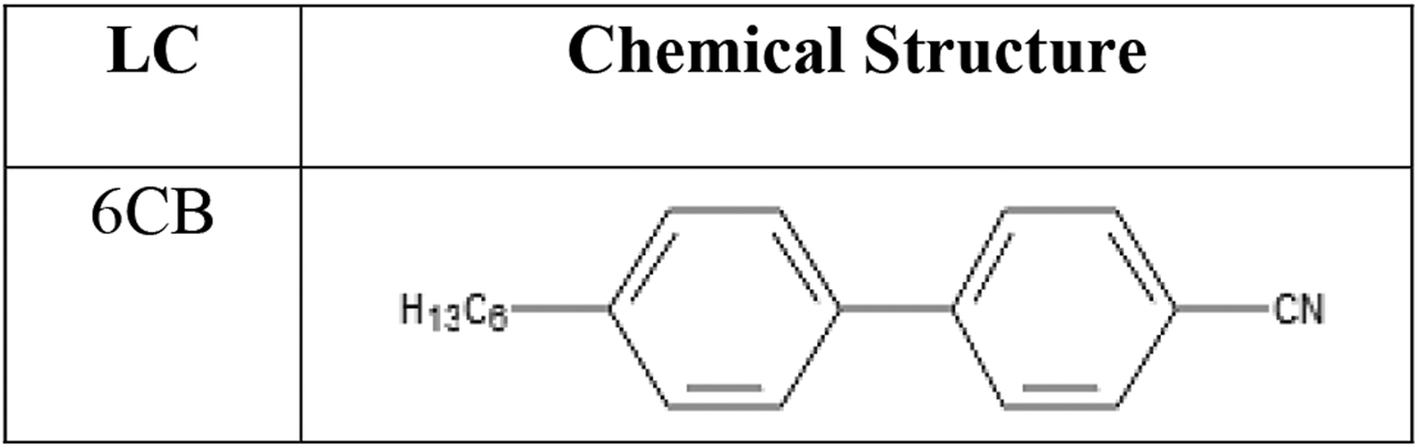
Molecular structures of 4-hexyl-4′-biphenylcarbonitrile (6CB).
Phase transition temperatures (T) and enthalpy changes (∆H) of 6CB.
| Material | Method | TCrN | ∆HCrN (J/g) | TNI | ∆HNI (J/g) |
|---|---|---|---|---|---|
| 6CB (cooling) | DSC | 2.3 | −57.3 | 27.23 | −3.1 |
DSC, differential scanning calorimetry.
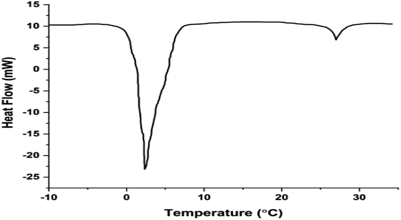
Differential scanning calorimetry (DSC) curve of 6CB compound.
2.2 Antenna design and modelling
The design flow of proposed antenna is shown in Figure 3 with step by step procedure. As shown in Figure 3, two glass substrates placed on each other and in between them a 0.005 mm air gap has been placed to fill 6CB NLC. A rectangular patch has been placed on top of the upper glass substrate.
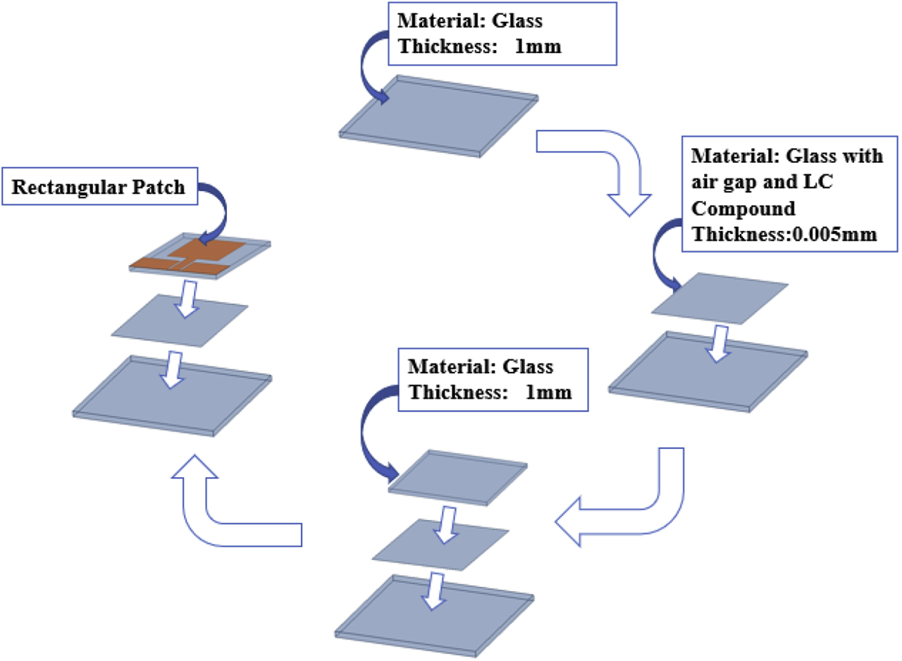
Antenna design flow.
The geometry of the proposed antenna is shown in Figure 4. Glass substrates of size 21 × 25 mm2 and 19 × 19 mm2 with relative permittivity of 6.43 has been utilised to design antenna models. In between these two glass substrates; 0.005 mm air gap is placed and filled with 6CB NLC compound. A rectangular patch having 10 × 11 mm2 size is excited with 50-Ω microstrip feed line (7 × 2 mm2) on the top of substrate. A symmetrical ground plane with coplanar waveguide feed of 5 × 8 mm2 size has been used in the design of proposed antenna. The dimensions of the proposed antenna calculated using standard rectangular patch antenna formulae [22] and are tabulated in Table 2.
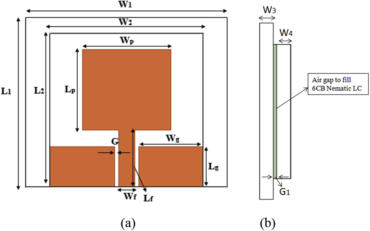
Proposed antenna (a) top view, (b) side view.
Dimensions of the proposed antenna.
| Parameters | L1 | W1 | L2 | W2 | Lp | Wp | Lf | Wf | Lg | Wg | G | G1 | W3, W4 |
|---|---|---|---|---|---|---|---|---|---|---|---|---|---|
| Values (in mm) | 21 | 25 | 19 | 19 | 10 | 11 | 7 | 2 | 5 | 8 | 0.5 | 0.005 | 1 |
Comparison table for proposed antennas.
| Antenna model | Results | Operating band (GHz) | BW (GHz) | Resonance frequency (GHz) | S11 (in dB) |
|---|---|---|---|---|---|
| Proposed antenna with air gap | Simulated | 4.01–7.85 | 3.84 | 5 | −24.2 |
| Measured | 4.03–7.66 | 3.63 | 5.08 | −25 | |
| Proposed antenna with 6CB NLC | Simulated | 2.61–4.45 | 1.84 | 3.3 | −29.75 |
| Measured | 2.62–4.44 | 1.82 | 3.37 | −30 |
NLC, nematic liquid crystal.
3 Results and discussions
Both the designed antennas are fabricated and compared the measured results with simulated results for validation is given in Table 3.
3.1 Proposed antenna with air gap
Figure 5 shows, both simulated and measured reflection coefficient and voltage standing wave ration (VSWR) of the proposed antenna with air gap. Designed antenna model-1 is providing bandwidth of 3.84 GHz and operating from 4.01 to 7.85 GHz with S11 of −24.2 dB from simulation studies. Similarly, fabricated antenna is providing bandwidth of 3.63 GHz, which is operating from 4.03 to 7.66 GHz with S11 of −25 dB by using combinational analyser. Amount of mismatch between feed line and antenna can be described by VSWR and a value between 2:1 is considered as best for practical antenna applications. From Figure 5 VSWR is ranging from 3.92 to 8.38 GHz for simulated and 3.93–8.37 GHz for measured results.
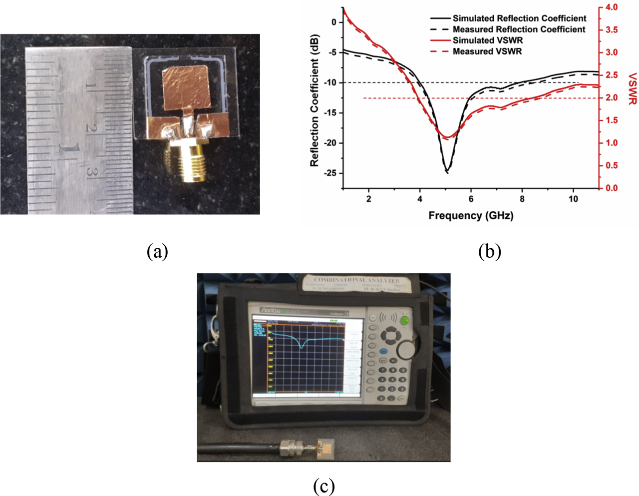
Experimentation results (a) Fabricated prototype, (b) Simulated and measured results of proposed antenna with air gap and (c) Reflection coefficient measurement on combinational analyser.
Radiation patterns of E-plane (φ = 0°) copolarization and cross-polarization, H-plane (φ = 90°) copolarization and cross-polarization at resonant frequency 5 GHz are shown in Figure 6. A Bidirectional radiation pattern is distributed in E-plane and omni-directional pattern is distributed in H-plane.
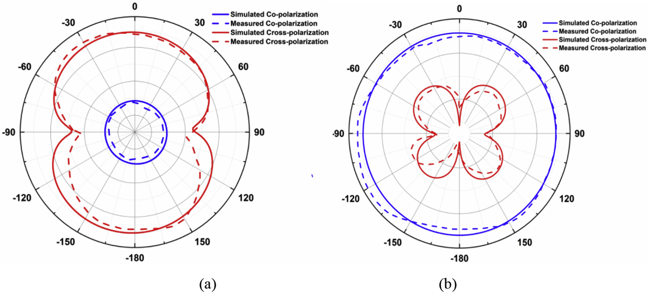
Simulated and measured radiation patterns of proposed antenna with air gap (a) Co and cross-polarization in E-Plane (b) Co and cross-polarization in H-Plane.
The simulated results of E-field distribution and surface current distribution at the resonant frequency 5 GHz is observed in Figure 7. In the E-field distribution of antenna model-1, the amplitude with minimum field distribution at the end of the rectangular patch, maximum field distribution is at the feeding of rectangular patch and at edges of the symmetrical ground plane. Similarly, the minimal surface current distribution is occurring at the end of the rectangular patch, maximal current distribution observed at the edge of symmetrical ground plane and at the feed line of the rectangular patch.
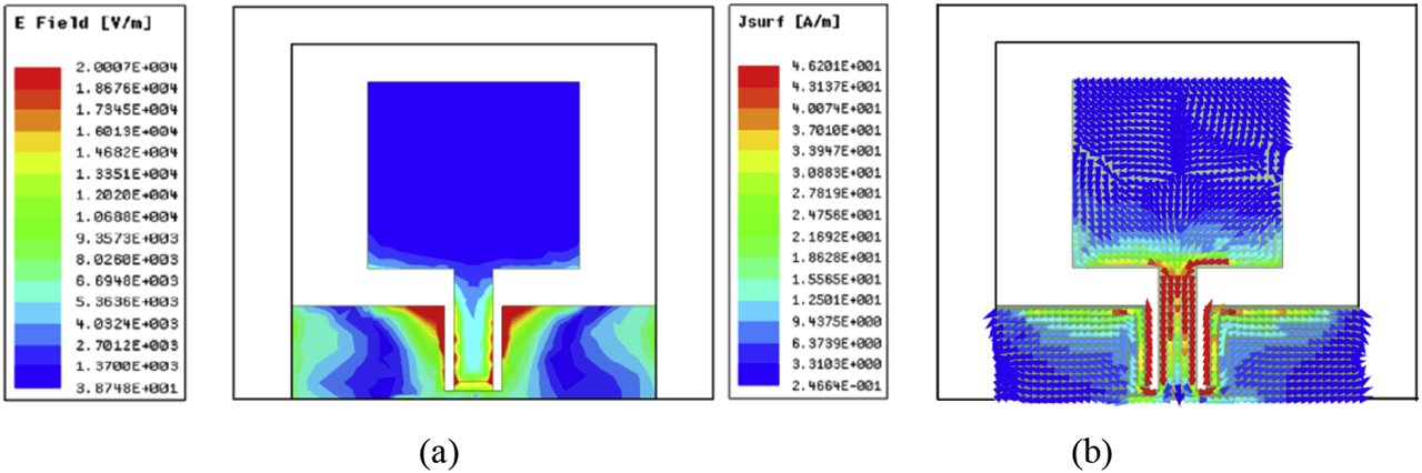
(a) E-field distribution at 5 GHz (b) Surface current distribution at 5 GHz.
Figure 8a provides the peak gain and radiation efficiency plots for proposed antenna. A gain value of 2.99 dB is observed at resonant frequency of the antenna model-1, and an average radiation efficiency of 87% is observed. Figure 8b provides 3-D plot of antenna gain for proposed antenna with air gap and the obtained gain of 2.99 dB.
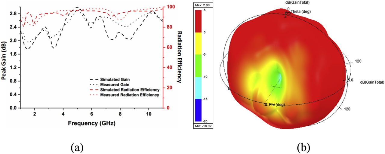
(a) Peak gain and radiation efficiency versus frequency plot and (b) simulated 3-D plot of antenna gain in dB at 5 GHz for proposed antenna with air gap.
3.2 Proposed antenna with 6CB nematic LC
Figure 9 shows, both simulated and measured reflection coefficient and VSWR of the proposed antenna with 6CB NLC filled in air gap between glass plates. Proposed antenna model-2 is providing bandwidth of 1.84 GHz, which is operating from 2.61 to 4.45 GHz with S11 of −29.75 dB in simulation. Similarly, fabricated antenna is providing bandwidth of 1.82 GHz, which is operating from 2.62 to 4.44 GHz with S11 of −30 dB by using combinational analyser. From Figure 9, VSWR is ranging from 2.55 to 4.54 GHz from simulation and 2.5–4.6 GHz for measured results.
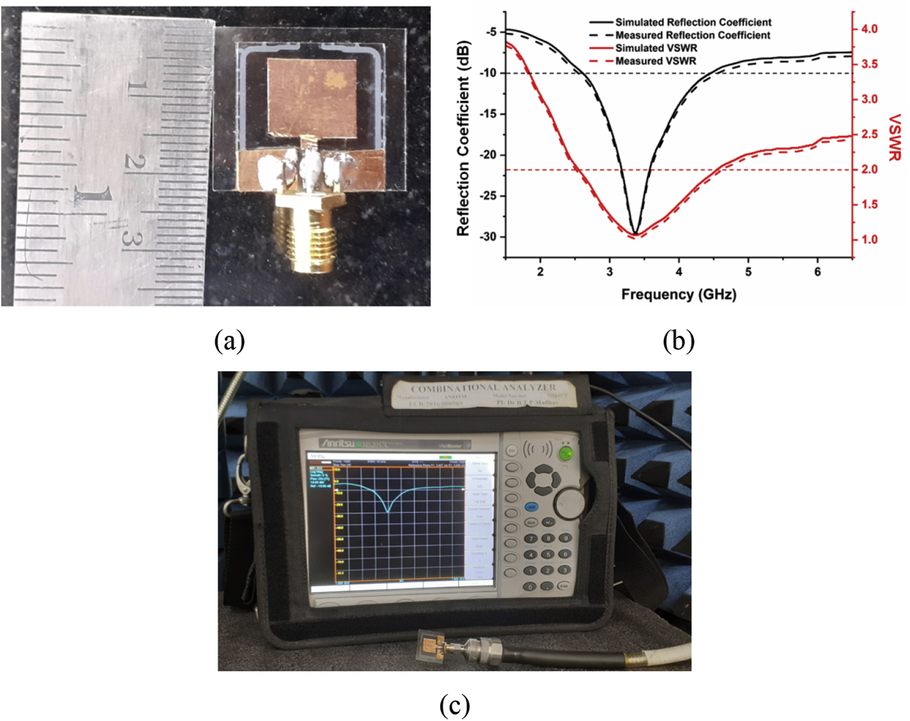
(a) Fabricated prototype, (b) simulated and measured results of proposed antenna with LC compound and (c) reflection coefficient measurement on combinational analyser.
Radiation patterns of E-plane (φ = 0°) in copolarization and cross-polarization, H-plane (φ = 90°) in copolarization and cross-polarization at resonant frequency 3.3 GHz are shown in Figure 10. The Bidirectional radiation pattern is distributed in E-plane with low cross-polarization and omni-directional pattern is distributed in co-polarization of H-plane with butterfly like low cross-polarization pattern.
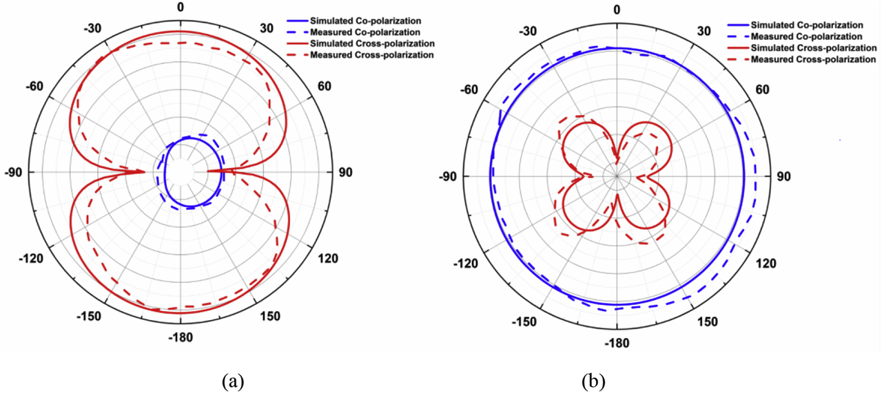
Simulated and measured radiation patterns of proposed antenna with LC compound at 3.3 GHz (a) copolymerization and cross-polarization in E-Plane and (b) copolymerization and cross-polarization in H-Plane. LC, liquid crystal.
The simulated results of E-field distribution and surface current distribution at the resonant frequency 3.3 GHz is observed in Figure 11. In the E-field distribution of proposed antenna model-2, maximum field distribution is at the feed line of the rectangular patch and edges of the symmetrical ground plane. Similarly, maximal current distribution occurs at the edge of symmetrical ground plane and at the feed line of the rectangular patch.
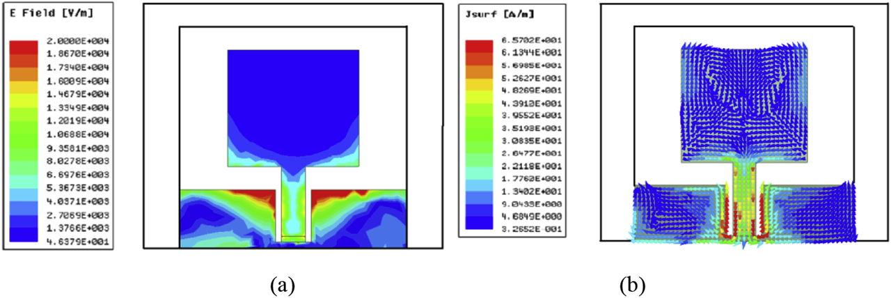
(a) E-field distribution at 3.3 GHz and (b) surface current distribution at 3.3 GHz.
Figure 12a provides the peak gain and radiation efficiency plots for proposed antenna model-2. A gain of 3.9 dB is observed at resonant frequency of proposed antenna and an average radiation efficiency of 88% is observed for proposed antenna model-2. Figure 12b provides 3-D plot of antenna gain for proposed antenna with 6CB LC compound.
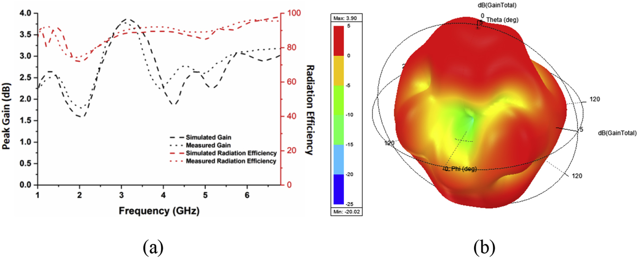
(a) Peak gain and radiation efficiency versus frequency plot and (b) simulated 3-D plot of antenna gain in dB for proposed antenna with 6CB liquid crystal.
4 Time domain analysis
A very high degree of correlation between information modules will place an important role in wireless communication systems. In this present work, two identical antennas of both proposed models have been taken and analysed in two cases with different distances from each other. To avoid losses in modulated data, correlation between transmitted and received signals must be high. Here, u(t) and v(t) are considered as transmitted and received signals, respectively. In order to find fidelity factor and transmitted characteristics of both the proposed antennas, two cases (face to face and side by side) with 25, 50 and 75 cm distances has been considered. Equation (1) can be used to find fidelity factor or correlation between transmitted and received signals.
4.1 Proposed antenna model-1 with air gap
Figures 13 and 14 provides correlation analysis between two face to face and side by side identical proposed antenna model-1 with air gap. Here, a Gaussian input signal has been transmitted between two identical antennas with separation of 25, 50 and 75 cm. To find the effective fidelity factor, amplitude has been normalised for received signal according to transmitted signal. When both the identical antennas are face to face, the obtained fidelity factor is 0.51, 1.24 and 1.97 ns for 25, 50 and 75 cm distances, respectively. When both the identical antennas are side by side, the obtained fidelity factor is 0.53, 1.26 and 2.02 ns for 25, 50 and 75 cm, respectively. Measured results of both face to face and side by side scenarios are having 5% more time delay from simulated results. From the analysis, it can be observed that when distance between transmitter antenna and received antenna increases then the time delay also increases.
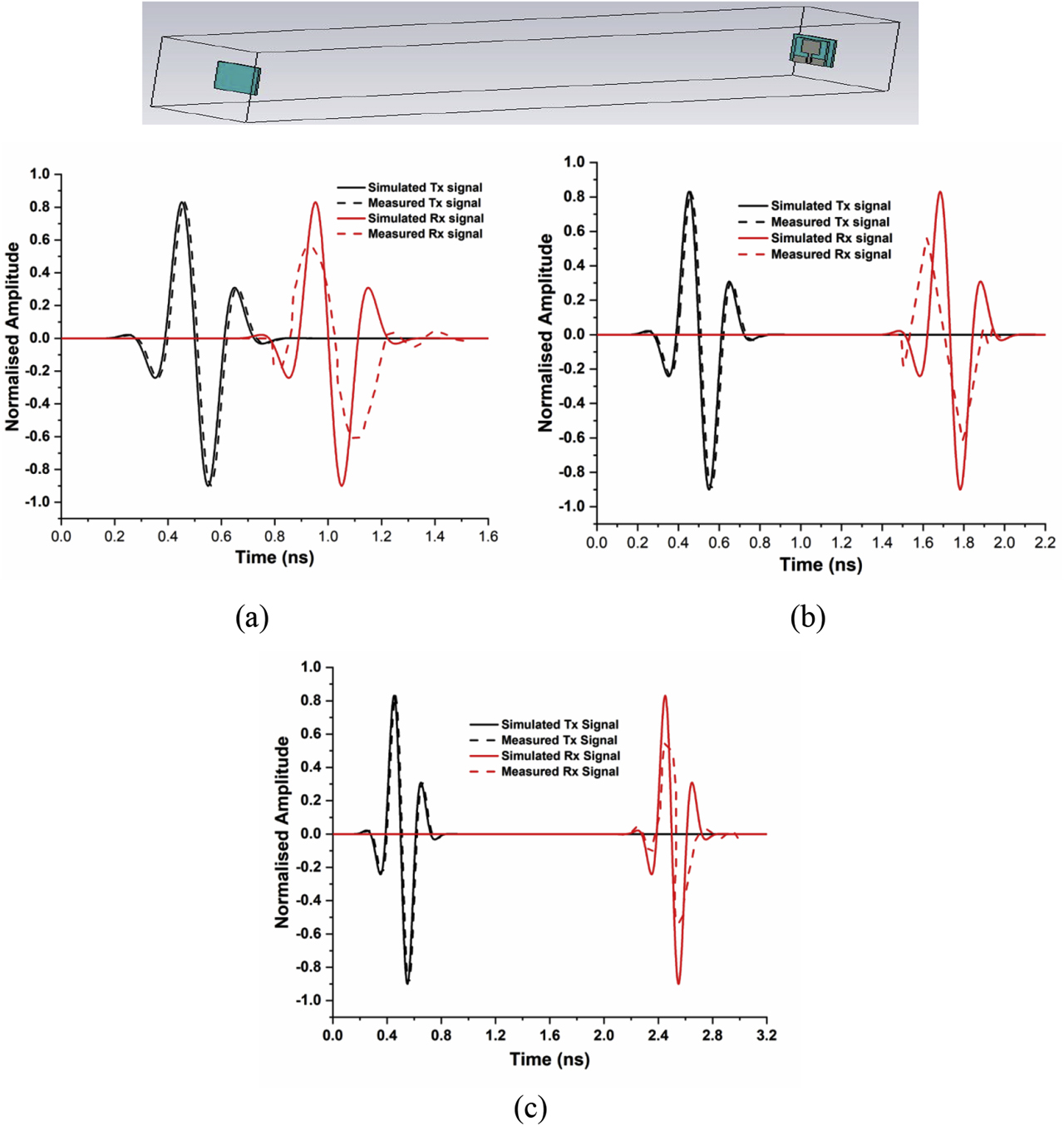
Correlation analysis between two face to face identical antennas with, (a) 25 cm distance, (b) 50 cm distance and (c) 75 cm distance.
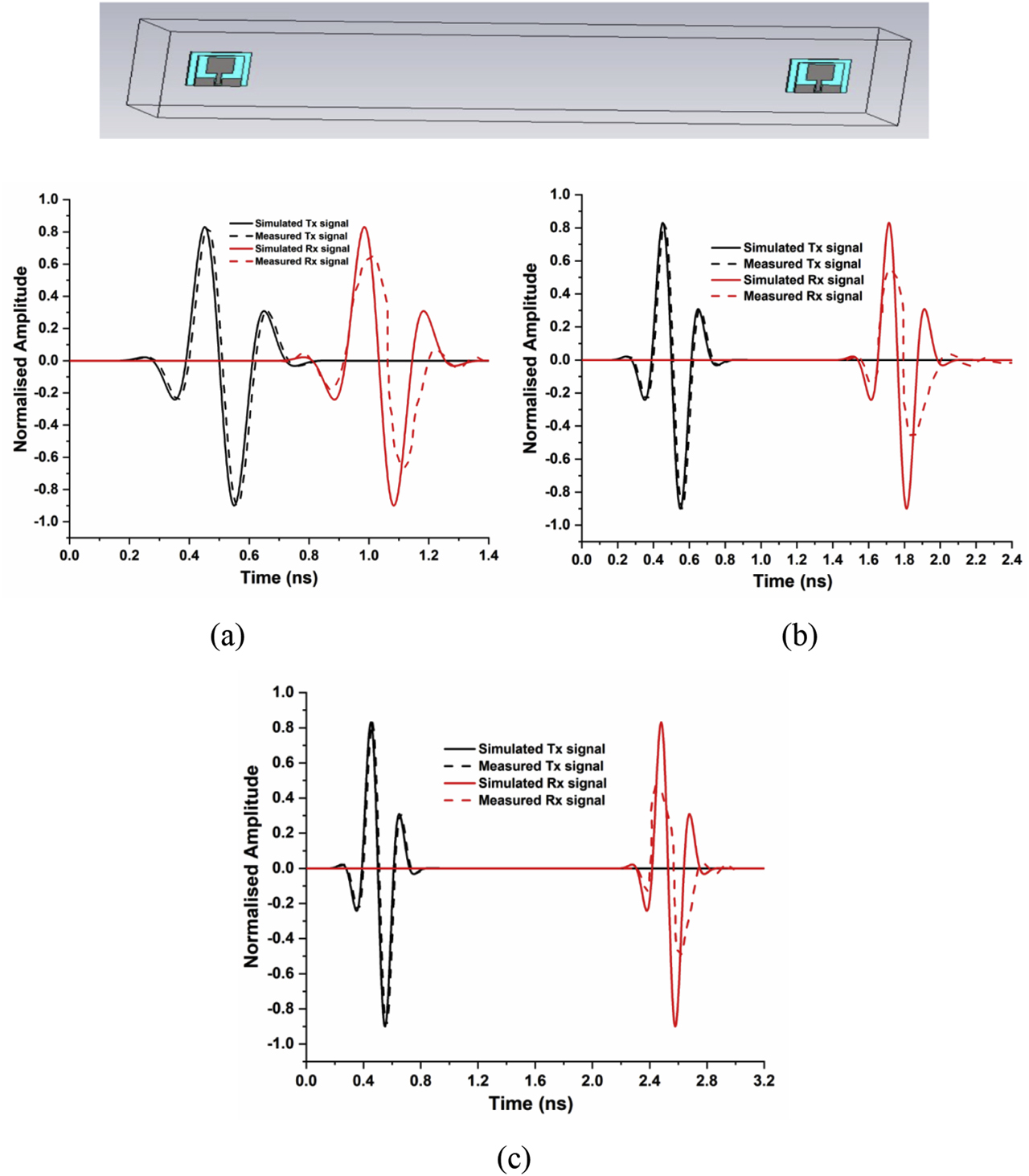
Correlation analysis between two side by side identical antennas with, (a) 25 cm distance, (b) 50 cm distance and (c) 75 cm distance.
4.2 Proposed antenna with 6CB LC
Figures 15 and 16, provides correlation analysis between two face to face and side by side identical proposed antennas with nematic 6CB LC. Here, a Gaussian input signal has been transmitted between two identical antennas with separation of 25, 50 and 75 cm. To find the effective fidelity factor, amplitude has been normalised for received signal according to transmitted signal. When both the identical antennas are face to face, the obtained fidelity factor is 0.51, 1.24 and 1.97 ns for 25, 50 and 75 cm distances respectively. When both the identical antennas are side by side, the obtained fidelity factor is 0.53, 1.26 and 2.02 ns for 25, 50 and 75 cm respectively. Measured results of both face to face and side by side scenarios are having 4% more time delay from simulated results. From the analysis, it can be observed that when distance between transmitter antenna and received antenna increases then the time delay also increases. From the comparative analysis table of Table 4, it has been observed that the glass substrate-based antenna and LC compound-based antenna are providing good bandwidths and compact in the dimension also. Comparison of simulated and measured reflection coefficient and measured peak gain versus frequency, for both the proposed antennas are given in Figure 17.
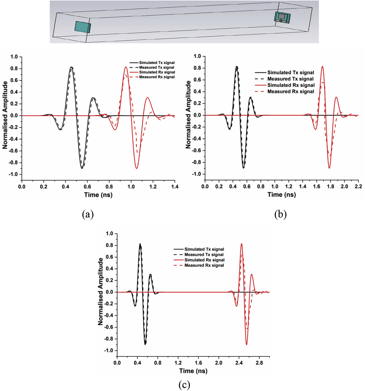
Correlation analysis between two face to face identical antennas with, (a) 25 cm distance, (b) 50 cm distance and (c) 75 cm distance.
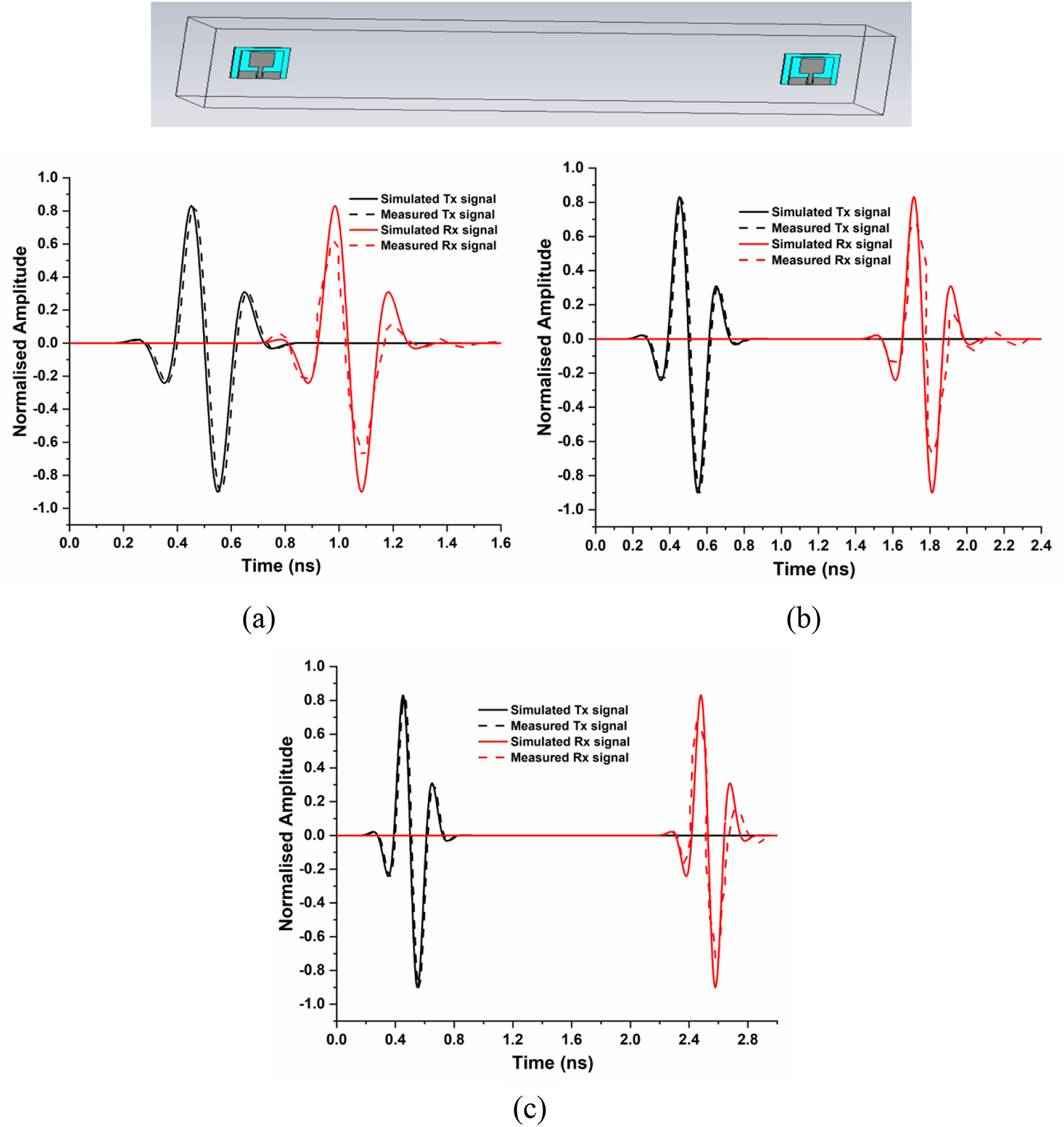
Correlation analysis between two side by side identical antennas with (a) 25 cm distance, (b) 50 cm distance and (c) 75 cm distance.
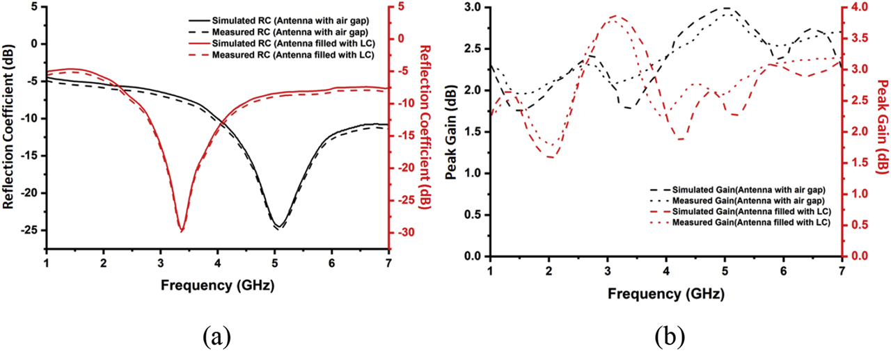
Comparison of (a) simulated and measured reflection coefficient and (b) simulated and measured peak gain versus frequency, for both the proposed antennas.
Comparison table of proposed antennas with existing literature.
| Reference | Material | Size | Operating band (in GHz) | BW (in GHz) | Resonating frequency (fr) | S11 (in dB) |
|---|---|---|---|---|---|---|
| [23] | Taconic glass reinforced Polytetrafluoroethylene (PTFE) | 22 × 15 × 1.53 mm | 5.43–5.66 | 0.23 | 5.5 | −30 |
| [24] | FR4 | 22 × 15 × 1.6 mm | 2.38–2.53 | 0.15 | 2.46 | −29 |
| [25] | Duroid 5880 | 40 × 48.4 × 1.5 mm | 2.44–2.46 | 0.02 | 2.45 | 31.5 |
| [26] | Rogers-R04003C | 22 × 15 × 1.6 mm | 2.36–2.55 | 0.19 | 2.4 | −18 |
| Proposed antenna – 1 | Glass | 21 × 25 × 2.005 mm | 4.01–7.85 | 3.84 | 5.0 | −24.2 |
| Proposed antenna – 2 | Glass, LC | 21 × 25 × 2.005 mm | 2.61–4.45 | 1.84 | 3.3 | −29.75 |
LC, liquid crystal.
5 Conclusion
The design of 6CB NLC rectangular patch antenna is proposed in this article. Antennas with both air gap and liquid crystal material filled are fabricated and analysed through combinational analyser for validation. Antenna model-1 with air gap is resonating at 5 GHz frequency and antenna model-2 with 6CB nematic LC is resonating at 3.3 GHz frequency. After filling LC into the antenna model-2, the resonating frequency is shifted to low frequency and observed that the return loss is reduced. This is the novel advantage in the antenna design that the operating band shifting to lower side without changing the physical dimensions of the antenna. Correlation between transmitted and received signals is experimented using time domain analysis with separation of 25, 50 and 75 cm, respectively. Both the fabricated antennas are tested, and the measured results in the chamber with combinational analyser are in good agreement with the simulated results.
Acknowledgments
DST through Fund for Improvement of S&T Infrastructure (FIST) grant of SR/FST/ET-II/2019/450. KLEF Internal funding project File no. KLEF/IF/SEP/2019/002.
Author contribution: All the authors have accepted responsibility for the entire content of this submitted manuscript and approved submission.
Research funding: None declared.
Conflict of interest statement: The authors declare no conflicts of interest regarding this article.
References
[1] T. L. Ting, “Technology of liquid crystal based antenna,” Opt. Express, vol. 27, no. 12, pp. 17138–17153, 2019, https://doi.org/10.1364/oe.27.017138.Search in Google Scholar PubMed
[2] R. D. Venkata, P. Pardhasaradhi, V. G. K. M. Pisipati, and P. V. D. Prasad, “Orientational order parameter studies on 3. Om and 3O. Om liquid crystals,” Phase Transit., vol. 88, no. 2, pp. 137–152, 2015, https://doi.org/10.1080/01411594.2014.961154.Search in Google Scholar
[3] M. Tejaswi, P. Pardhasaradhi, B. T. P. Madhav, M. C. Rao, N. Krishna Mohan, and R. K. N. R. Manepalli, “Spectroscopic studies on liquid crystalline n-hexyloxy-cyanobiphenyl with dispersed citratecapped gold nanoparticles in visible region,” Liq. Cryst., vol. 47, no. 6, pp. 918–938, 2019, https://doi.org/10.1080/02678292.2019.1688874.Search in Google Scholar
[4] P. S. Sastry, P. Pardhasaradhi, C. Srinivasu, V. G. K. M. Pisipati, and P. V. Datta Prasad, “Synthesis, characterisation and phase transition studies in N-(-4-ethyloxybenzylydene)-4′-alkoxyanilines,” Liq. Cryst., vol. 43, no. 5, pp. 632–638, 2016, https://doi.org/10.1080/02678292.2015.1131342.Search in Google Scholar
[5] P. Jayaprada, M. C. Rao, P. Pardhasaradhi, P. V. D. Prasad, R. K. N. R Manepalli, and V. G. K. M. Pisipati, “Optical studies of n-octyloxy-cyanobiphenyl (8ocb) with dispersed ZnO nanoparticles for display device application,” Optik, vol. 185, pp. 1226–1237, 2019, https://doi.org/10.1016/j.ijleo.2019.04.060.Search in Google Scholar
[6] D. Gennes, P. Gilles, and J. Prost, The physics of liquid crystals, vol. 83, Oxford, Oxford University Press, 1993.10.1093/oso/9780198520245.001.0001Search in Google Scholar
[7] T. W. Kim, J.S. Park, and S.O. Park, “A theoretical model for resonant frequency and radiation pattern on rectangular microstrip patch antenna on liquid crystal substrate,” IEEE Trans. Antenn. Propag., vol. 66, no. 9, pp. 4533–4540, 2018, https://doi.org/10.1109/tap.2018.2851304.Search in Google Scholar
[8] S. F. Jilani, M. O. Munoz, H. QammerAbbasi, and A. Alomainy, “Millimeter-wave liquid crystal polymer based conformal antenna array for 5G applications,” IEEE Antenn. Wireless Propag. Lett., vol. 18, no. 1, pp. 84–88, 2018. https://doi.org/10.1109/LAWP.2018.2881303.Search in Google Scholar
[9] T. Anilkumar, B. T. P. Madhav, M. Venkateswara Rao, and B. Prudhvi Nadh, “Bandwidth reconfigurable antenna on a liquid crystal polymer substrate for automotive communication applications,” AEU-Int. J. Electron. C., vol. 117, p. 153096, 2020, https://doi.org/10.1016/j.aeue.2020.153096.Search in Google Scholar
[10] A. C. Polycarpou, A. MariosChristou, and N. C. Papanicolaou, “Tunable patch antenna printed on a biased nematic liquid crystal cell,” IEEE Trans. Antenn. Propag., vol. 62, no. 10, pp. 4980–4987, 2014, https://doi.org/10.1109/tap.2014.2344099.Search in Google Scholar
[11] M. Wang, C. Trlica, M. R. Khan, M. D. Dickey, and J. J. Adams, “A reconfigurable liquid metal antenna driven by electrochemically controlled capillarity,” J. Appl. Phys., vol. 117, no. 15, 2015, Art no.194901. https://doi.org/10.1063/1.4919605.Search in Google Scholar
[12] G. J. Hayes, J.H. So, A. Qusba, M. D. Dickey, and G. Lazzi, “Flexible liquid metal alloy (EGaIn) microstrip patch antenna,” IEEE Trans. Antenn. Propag., vol. 60, no. 5, pp. 2151–2156, 2012, https://doi.org/10.1109/tap.2012.2189698.Search in Google Scholar
[13] A. M. Morishita, C. K. Y. Kitamura, A. T. Ohta, and W. A. Shiroma, “A liquid-metal monopole array with tunable frequency, gain, and beam steering,” IEEE Antenn. Wirel. Propag. Lett., vol. 12, pp. 1388–1391, 2013, https://doi.org/10.1109/lawp.2013.2286544.Search in Google Scholar
[14] C. Hua, Z. Shen, and J. Lu, “High-efficiency sea-water monopole antenna for maritime wireless communications,” IEEE Trans. Antenn. Propag., vol. 62, no. 12, pp. 5968–5973, 2014, https://doi.org/10.1109/tap.2014.2360210.Search in Google Scholar
[15] C. Hua and Z. Shen, “Shunt-excited sea-water monopole antenna of high efficiency,” IEEE Trans. Antenn. Propag., vol. 63, no. 11, pp. 5185–5190, 2015, https://doi.org/10.1109/tap.2015.2477418.Search in Google Scholar
[16] M. Zou, Z. Shen, and J. Pan, “Frequency-reconfigurable water antenna of circular polarization,” Appl. Phys. Lett., vol. 108, no. 1, p. 014102, 2016, https://doi.org/10.1063/1.4939455.Search in Google Scholar
[17] Y. Li and K. M. Luk, “A water dense dielectric patch antenna,” IEEE Access, vol. 3, pp. 274–280, 2015, https://doi.org/10.1109/access.2015.2420103.Search in Google Scholar
[18] Z. Hu, Z. Shen, and W. Wu, “Reconfigurable leaky-wave antenna based on periodic water grating,” IEEE Antenn. Wireless Propag. Lett., vol. 13, pp. 134–137, 2014, https://doi.org/10.1109/lawp.2014.2298245.Search in Google Scholar
[19] C. Hua, Z. Shen, and J. Lu, “High-efficiency sea-water monopole antenna for maritime wireless communications,” IEEE Trans. Antenn. Propag., vol. 62, no. 12, pp. 5968–5973, 2014, https://doi.org/10.1109/tap.2014.2360210.Search in Google Scholar
[20] S. D. Mahamine, R. S. Parbat, S. H. Bodake, and M. P. Aher, “Effects of different substrates on rectangular microstrip patch antenna for S-band,” in 2016 International Conference on Automatic Control and Dynamic Optimization Techniques (ICACDOT), IEEE, 2016, pp. 1142–1145.10.1109/ICACDOT.2016.7877765Search in Google Scholar
[21] G. W. von Gray. Molecular Structure and the Properties of Liquid Crystals, London-New York, Academic Press, 1962.Search in Google Scholar
[22] L. Liu and R. J. Langley, “Liquid crystal tunable microstrip patch antenna,” Electron. Lett., vol. 44, no. 20, pp. 1179–1180, 2008, https://doi.org/10.1049/el:20081995.10.1049/el:20081995Search in Google Scholar
[23] C. A. Balanis, Antenna Theory: Analysis and Design, New Jersey, John Wiley & Sons, 2016.Search in Google Scholar
[24] Z. X. Yang, H. C. Yang, J. S. Hong, and Y. Li, “Bandwidth enhancement of a polarization-reconfigurable patch antenna with stair-slots on the ground,” IEEE Antenn. Wireless Propag. Lett., vol. 13, pp. 579–582, 2014, https://doi.org/10.1109/LAWP.2014.2312971.Search in Google Scholar
[25] E. T. Aye and C. M. Nwe, “Rectangular microstrip patch antenna array for RFID application using 2.45 GHz frequency range,” Int. J. Sci. Res., vol. 4, no. 6, pp. 1–2, 2014.Search in Google Scholar
[26] N. Hasan, “Design of single & 1 × 1 microstrip rectangular patch antenna array operating at 2.4 GHz using ADS,” Int. J. Eng. Res. Afr., vol. 2, no. 5, pp. 2124–2127, 2012.Search in Google Scholar
© 2020 Walter de Gruyter GmbH, Berlin/Boston
Articles in the same Issue
- Frontmatter
- General
- Graphene in curved Snyder space
- Dynamical Systems & Nonlinear Phenomena
- Resonant interactions between the fundamental and higher harmonic of positron acoustic waves in quantum plasma
- Hydrodynamics
- Analysis of Carreau fluid flow by convectively heated disk with viscous dissipation effects
- Quantum Theory
- From quantum foundations to spontaneous quantum gravity – An overview of the new theory
- Variational principle for time-periodic quantum systems
- Solid State Physics & Materials Science
- Design and analysis of 6CB nematic liquid crystal–based rectangular patch antenna for S-band and C-band applications
- First-principles study of structures, elastic and optical properties of single-layer metal iodides under strain
- Influence of deposition time and annealing treatments on the properties of chemically deposited Sn2Sb2S5 thin films and photovoltaic behavior of Sn2Sb2S5-based solar cells