Effect of Urea on the Shape and Structure of Carbon Nanotubes
-
M. R. Elamin


Abstract
Coiled multiwall carbon nanotubes (MWCNTs) were prepared on Fe, Co, and Ni metal oxides supported on α-Al2O3 using urea as fuel and catalyst surface modifying agent by catalytic chemical vapour deposition (CCVD). The shape of the nanotubes was influenced by the addition of urea, where coiled and uncoiled tubes were obtained in the presence and absence of urea, respectively. The MWCNTs were characterized using scanning electron microscopy (SEM), transmission electron microscopy (TEM), X-ray diffraction (XRD), and nitrogen adsorption analysis. The coiling/uncoiling of the nanotubes was visualized from the SEM and TEM images of the prepared specimens. The XRD data showed the characteristic peaks of the nanotubes. BET analysis of the coiled tubes revealed 85.57 m2 g−1 surface area with a pore diameter 102.2–110.8 Å. A mechanism for the nanotubes coiling is suggested.
1 Introduction
Since Iijima’s original publication in Nature [1], [2], carbon nanotubes (CNTs) have become a focal point in research. Their use in various applications is facilitated by their outstanding electrical, optical, and mechanical properties [3], [4]. Methods such as arc discharge [1], laser vaporization [5], and chemical vapour deposition [6] are the most popular ones for the preparation of CNTs. CNTs with coil or helix structures were synthesized by Oberlin et al. [7]. Dunlap [8], Itoh et al. [9] and Itoh and Ihara [10] theoretically predicted the mechanisms of their formation. Coiled CNTs are obtained by incorporating pairs of pentagon and heptagon rings into the basic hexagonal rings of the nanotube network [11], [12]. Such coiled carbon nanotubes could be grown via catalytic chemical vapour deposition (CCVD) by decomposing a hydrocarbon over supported transition metals [13]. The type of catalyst, carbon source, reaction temperature, and gas flow rate are the factors that determine the shape of CNTs [14]. During CNT formation, transition metals react with carbon through the overlap of their d orbitals with the p orbitals of the carbon, and the extent of reactions is dependent on the number of vacancies in the d orbitals. Therefore, Fe, Ni, and Co with a few d orbital vacancies are the most popular CNT catalysts [15]. For CNT synthesis, a carbon source such as CO [16] and hydrocarbons such as C2H4, C2H2, xylene [17], and alcohol [18] are passed over a heated catalyst upon which carbon atoms start to precipitate as carbon nanotubes having the sp2 configuration [19], [20]. A blend of nanocoils as well as worm-like and helical carbon nanotubes were grown onto Fe deposited on a ceramic plate at 450°C [14]. Coiled carbon nanotubes were prepared on Fe/Mo supported on MgO via a combustion method using citric acid as the foaming and combustion additive [21].
In this work, we synthesized coiled CNTs by CCVD of ethanol on Fe, Co, and Ni nanoparticles supported on alumina at ambient pressure, 700°C, and N2 gas flow with the addition of urea. The objectives of this work were to (i) probe the morphology and structure of the coiled carbon nanotubes using X-ray diffraction (XRD), transmission electron microscopy (TEM), scanning electron microscopy (SEM), and BET surface area techniques; (ii) investigate the influence of urea on the growth of coiled nanotubes under the preparation conditions; and (iii) suggest a mechanism of growth of the coiled CNTs.
2 Materials and Methods
2.1 Preparation of the Catalysts
α-Aluminium oxide (α-Al2O3) powder (AR grade, BHD) was calcined in a muffle furnace at 1200°C for 4 h. The white powder was cooled and ground in an agate mortar and used as support material to encapsulate the transition-metal oxide catalysts. The calculated masses of cobalt acetate tetrahydrate (98.5%, LOBA Chemie), iron(II) sulfate heptahydrate, and nickel nitrate (AR grade 99.0%, BDH) were weighed separately and dissolved in 40 ml of methanol (AR grade, BDH). Then 5.0 g of urea and 3.0 g of calcined α-Al2O3 were added to give a ratio of 5% Co, Ni, and Fe. The suspension was stirred for 1 h at 600 rpm at room temperature. The mixture was evaporated to dryness on a hotplate. The dry cakes were collected, ground in an agate mortar, calcined in a porcelain evaporating dish in a muffle furnace at 600°C for 3 h, and cooled. The obtained catalysts were ground again and preserved in plastic containers for further characterization.
2.2 Synthesis of Carbon Nanotubes
The CCVD technique was employed in the preparation of CNTs. About 0.2 g of each catalyst was weighed in a dry porcelain boat, evenly spread at the bottom of the boat, and placed in a tubular furnace reactor consisting of a heater and a stainless steel (SS) cylinder of 800 mm in length and 40 mm inner diameter. The exhaust joint was attached to the SS cylinder and connected to a fume hood. Nitrogen gas at 40 l h−1 (11.1 cm3 s−1) was allowed to flow through the cylinder while the temperature of the furnace was increased gradually at the rate of 20°C min−1 to the reaction temperature of 700°C. When the temperature reached about 550°C, a 500-ml Pyrex glass conical flask containing 40 ml of pure ethanol was heated to boiling on a hot plate. As the temperature of the furnace attained 700°C, the ethanol vapour was carried by the nitrogen gas current to the reaction zone in the SS cylinder at the rate of ~2 ml of C2H5OH per minute. After all ethanol was evaporated, the reaction was kept at 700°C for a further 20 min and allowed to cool under nitrogen current until 250°C before finally switching off the nitrogen flow. On attaining room temperature, the boat and its content were removed. The removal of the catalysts and supports was carried out by immersing the crude CNTs in a mixture of 30 ml of concentrated hydrochloric and nitric acids in the ratio of 3:1 and boiled gently on the hotplate in the fume hood for 60 min. The mixture was then cooled and diluted with distilled water and filtered using a water pump, washed till neutral, and oven-dried at 80°C for 4 h.
2.3 Characterization
The crystal structures of the α-aluminium support, the catalyst, and CNTs were investigated using a diffractometer (D8 Advance; Bruker, Billerica, MA, USA) using Cu Kα radiation, with λ=0.15406 nm, accelerating voltage=40 kV, and in the scanning angle range 20–80°. The morphology of all the prepared samples was inspected using a scanning electron microscope (FE-SEM, JEOL-6700F; JEOL Ltd, Akishima, Tokyo, Japan). The CNT samples were gold-coated after drying at 105°C. The TEM images were acquired using a JEOL JEM 2100 microscope (JEOL Ltd, Akishima, Tokyo, Japan) operated at an accelerating voltage of 200 kV. Carbon-coated copper grids (300 mesh) were used, and the sample was dispersed in an aqueous solution and left to dry. The surface characteristics and porosity of the nanotubes were studied using the nitrogen adsorption at its boiling point (77 K) using an ASAP 2020 (Micromeritics) instrument (Micromeritics Instrument Corp., Norcross, GA, USA). Prior to each analysis, the samples were outgassed at 250°C for 6 h by a constant flow of helium. The porosity of the nanotubes was obtained employing the BET (Brunauer, Emmett, and Teller) equation and the t-plot method of Lippens and De Boer [22].
3 Results and Discussion
3.1 XRD of the Support and Catalysts
Figure 1a shows the XRD patterns of the calcined α-Al2O3 and metal oxides without the addition of urea. The 2θ and Miller indices values are 25.594° (0 1 2), 35.197° (1 0 4), 37.804° (1 1 0), 43.381° (1 1 3), 52.588° (0 2 4), 57.538° (1 1 6), 59.782° (2 1 1), 61.333° (0 1 8), 66.547° (2 1 4), 68.230° (3 0 0), and 76.909° (2 1 5) for the α-alumina XRD peaks [23], [24]. The pattern confirmed that α-Al2O3 was successfully prepared [25] to be used as a support for the catalyst nanoparticles. These results confirmed the work of Cava et al. [26], who found that heating different phases of aluminium oxides to high temperature resulted in α-Al2O3 with the same XRD peaks as obtained here. There are no significant extra peaks due to the metal oxides (Fig. 1a). The effect of urea on the XRD of nanoparticles can be obviously seen (Fig. 1b). The XRD pattern of the Co/Al2O3/urea nanoparticles is almost identical to that of α-Al2O3 but with a new peak at 2θ=33.5°, which may be attributed to a Co phase [27]. Also, the intensity of the peaks is enhanced and shifted to higher values, indicating the doping of Co in the α-Al2O3 lattice [28]. On the other hand, the XRD pattern of Fe/Al2O3/urea nanoparticles showed an Fe phase peak at 2θ=63.0° in addition to the typical peaks of the support [29]. The peaks at 2θ=37.0° and 63.0° characteristic of NiO nanoparticles [30] emerged when urea was added. The particle size of Co/Al2O3/urea, Ni/Al2O3/urea, and Fe/Al2O3/urea were found to be 53, 59, and 57 nm, respectively, as calculated using the Scherer equation. The good dispersion of the catalyst in the α-Al2O3 support is evidenced by the evolution of some characteristic peaks of the transition-metal oxide, as previously depicted by Kathyayini et al. [25].

XRD patterns of (a) α-Al2O3, Co/Al2O3, Ni/Al2O3, and Fe/ Al2O3; and (b) α-Al2O3, Co/Al2O3/urea, Ni/Al2O3/urea, and Fe/ Al2O3/urea. *Metal oxides peaks.
3.2 SEM of the Support and Catalysts
The SEM image of the α-Al2O3 nanoparticles shows granular clustered particles (Fig. 2a) in the range 30–40 nm. The nanoparticles exhibit many spaces and voids, providing suitable sites for the encapsulation of the transition-metals catalysts.
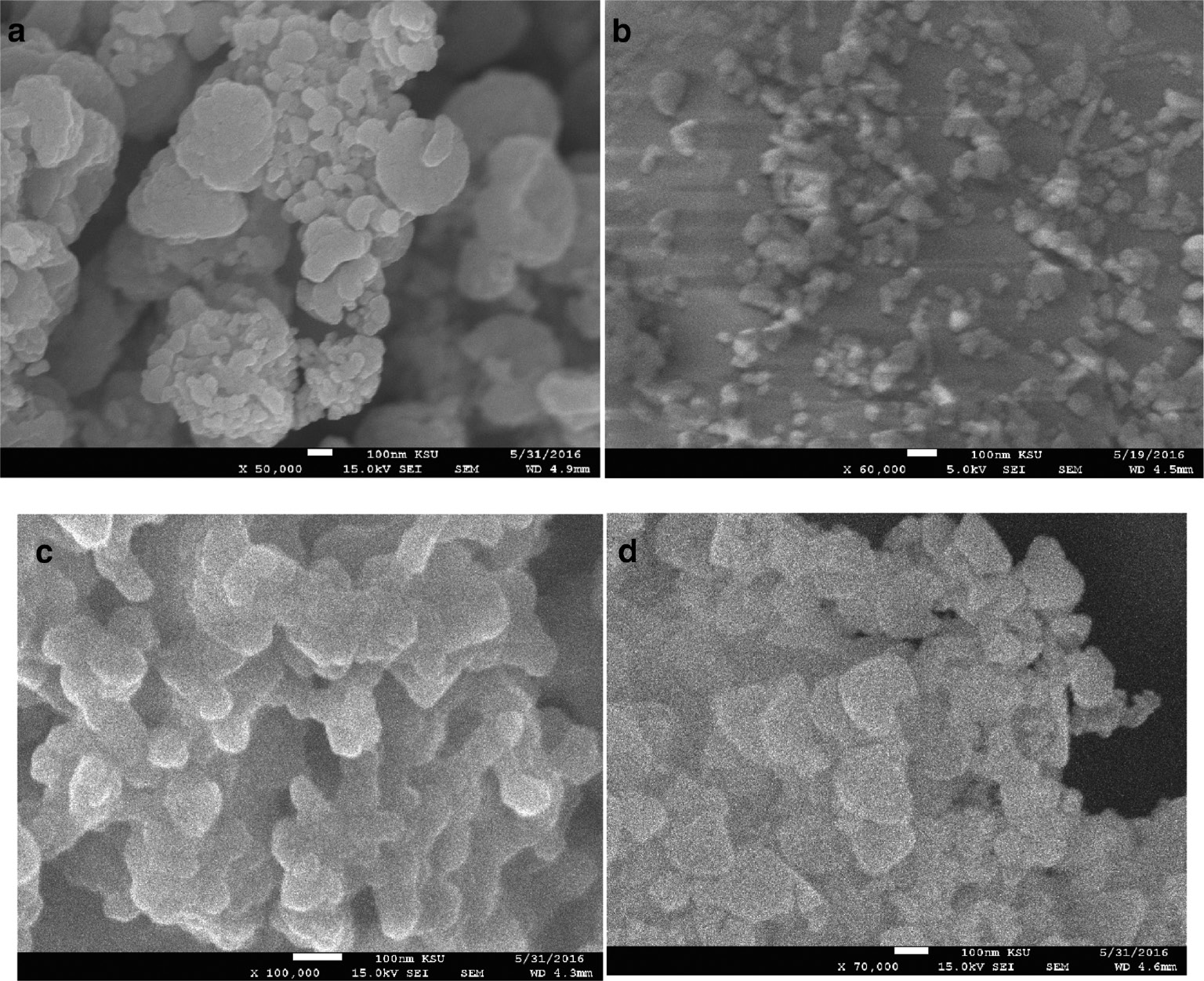
SEM images of (a) α-Al2O3, (b) Co/Al2O3, (c) Co/Al2O3/urea, and (d) Fe/Al2O3/urea nanoparticles.
The SEM image of Co/Al2O3 nanoparticles (Fig. 2b) without the addition of urea shows fine particles of size about 30 nm. On the other hand, the SEM images (Fig. 2c and d) clearly confirm an average size of ~59 and 57 nm of the catalyst as shown by XRD (Fig. 1) for the prepared Co/Al2O3/urea and Fe/Al2O3/urea nanoparticles. Deposition of these oxides on the Al2O3 support led to the cementing of the granules of the metal oxide nanoparticles with each other at the elevated calcination temperature. The addition of urea resulted in the transformation of the nanoparticles from spherical to elongated, non-spherical structures. The variation in the images of nanoparticles with and without urea may be due to the formation of differently shaped CNTs. The catalyst sizes reported here might have led to the formation of MWCNTs, as indicated in a previous similar work [31]. As the catalyst particle size and shape play a vital role in the CVD synthesis of carbon nanotubes, we can control the CNT properties by improving the characteristics of the catalysts. It has been reported that the catalyst grain is detrimental to the structure of a carbon nanocoil, and the irregularity of carbon extrusion speed in the different parts of the catalyst grain leads to the helical growth of the coiled CNTs [32]. The change of the catalyst from spherical (isotropic) to elongated semi-oval (anisotropic) shape is a necessary condition for coiled CNT synthesis [33]. Urea can preferentially bind to certain planes of the nanoprticle crystal by its functional groups (C=O and NH2) [34], [35], [36] prior to its composition, thereby modifying its shape and surface properties. As a consequence of this anisotropy, carbon deposition on the catalyst planes can take place. This finding is in agreement with that of Chen et al. [37] who attributed the coiling of straight CNTs to the strong catalytic anisotropy of carbon deposition between different crystal faces.
3.3 XRD of the CNTs
The XRD pattern of Figure 3a presents an example of pristine CNTs, with broad peaks that may have resulted from the overlap of the CNT peaks with those of the catalyst nanoparticles. In contrast, the XRD patterns of the CNTs (Fig. 3b) exhibit diffraction peaks at 2θ=~26.2° and 43.2° for the CNTs after purification. These peaks were, respectively, ascribed to the (0 0 2) and (1 0 0) reflections of hexagonal structures of graphite [38] in accordance with standard data (ICDD, PDF file no. 00-025-0284). Sankal and Kaynak [39] reported that the XRD spectra of all CNTs have virtually the same first-order diffraction peak at 2θ=25.6°, while the XRD peaks at 2θ=26.09° and 43.09° were allocated to graphitic MWCNTs in a similar study [29]. The addition of urea increased the XRD peak intensity of CNTs grown on Co/Al2O3/urea, Ni/Al2O3/urea, and Fe/Al2O3/urea relative those of CNTs grown on metal oxide/Al2O3 only, as can be deduced from Figure 3b.

XRD patterns of (a) pristine CNTs and (b) CNTs with and without urea addition.
3.4 Morphological Study of CNTs
Figure 4a shows the uncoiled or rather straight CNTs grown on Co/Al2O3 nanoparticles. On the other hand, Figures 4b and 5a and b display the SEM image of CNTs revealing different sizes of MWCNTs that have bent and coiled structures formed on the metal oxide/Al2O3/urea catalyst. The variation of the CNTs’ shape may be attributed to the addition of urea, which clearly changed the nanoparticle structure and size (Fig. 2b vs. Fig. 2c and d). This finding agrees with those of Csató et al. [40], who employed a Co/Fe catalyst supported on Al2O3 and CaCO3 to prepare coiled carbon nanotubes by passing acetylene and N2 at 700°C.

SEM image of CNTs prepared on Ni/Al2O3 catalyst (a) without urea and (b) with urea.

SEM image of CNTs prepared on (a) Co/Al2O3/urea and (b) Fe/Al2O3/urea catalysts.
The TEM image (Fig. 6a) demonstrates long coiled carbon nanotubes that were formed on iron oxide/Al oxide/urea at the relatively higher deposition time used in this work. Mohammed et al. [41] have reported that longer nanotubes are formed at a higher deposition time of about 10 min. Moreover, the strong interaction of Fe, Ni, and Co with the growing CNTs renders the efficient formation of high-curvature CNTs [42]. Without the addition of urea, uncoiled nanotubes are formed (Fig. 6b). This result confirms the coiling of nanotubes grown on nanoparticles treated with urea.

TEM image of (a) coiled and (b) uncoiled CNTs.
The TEM image (Fig. 7a) shows a CNT of 35 nm diameter, which reveals a hollow inner channel of about 10 nm nanotubes with a wall consisting of 32 concentric tubes (Fig. 7b). The inter-layer spacing between the sheets is 0.34 nm, which is consistent with the ideal graphitic inter-layer spacing of 3.30–3.33 Å [43], [44], [45]. The high magnification also confirmed the absence of embedded catalysts and impurities inside the tube or between the concentric tubes.
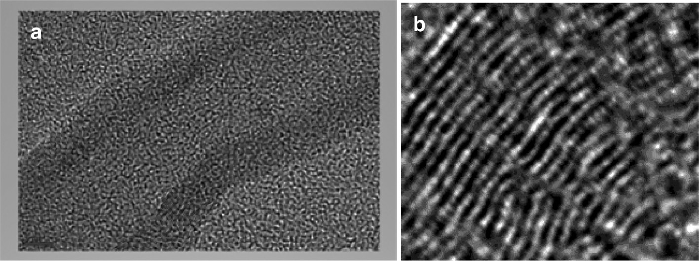
TEM image of nanotubes (a) with concentric tubes (b) grown on Co/Al2O3/urea.
3.5 Coiled Tubes’ Growth Mechanism
Though nanotubes primarily consist of hexagonal rings of carbon atoms, still non-hexagonal rings, mainly heptagonal and pentagonal structures, are also present. The incorporation of pentagons and heptagons into the hexagonal network leads to the formation of non-straight nanotubes such are coiled, bent, and toroidal [46]. As can be seen in Figure 8a and b, the twisting of the nanotubes (knees) may indicate the inclusion of pentagons and heptagons into the hexagonal network and the subsequent initiation of the coiling process. This is consistent with the kinetics of coiled CNT growth mechanism, which is based on the heptagon–pentagon construction theory. In addition, the comparatively low growth temperature applied in the CCVD method (700°C) may induce the slow movement of carbon atoms and the formation of non-hexagonal carbon rings [47], leading to the growth of coiled CNTs [32]. Figure 8c shows the final coiling stage that subsequently follows the bending.

SEM image of CNTs at the (a, b) bending (knees) and (c) coiled stages.
3.6 BET Analysis
The adsorption–desorption isotherms of the coiled nanotubes prepared on Co/Al2O3/urea are presented in Figure 9. The isotherm is Type V as classified by the IUPAC [48] with H3 hysteresis, indicating aggregates (loose assemblages) of plate-like particles forming slit-like pores. The specific surface is 85.57 m2 g−1 as estimated by applying the BET method. The pore volume and pore diameter were found to be 0.2199 cm3 g−1 and 106.50 Å, respectively. The surface area obtained in this work is within the ~15–300 m2 g−1 range recorded for MWCNTs [49], [50], [51], [52]. As for MWCNTs, Peigney et al. [53] reported a surface area of 50 m2 g−1 for 35-nm-diameter 40-walled MWCNTs. Concurrently, nanotubes of diameter ≈35 nm (Fig. 6a) and 32 walls (Fig. 6b) are produced by applying this procedure.

N2 adsorption-desorption isotherms of MWCNTs grown on Co/Al2O3/urea.
4 Conclusion
This study demonstrates that coiled MWCNTs can be prepared on metal oxide catalysts embedded in aluminium oxide and urea, which modify the nanoparticle surface. XRD data of the support and the catalysts showed excellent interaction behaviour between aluminium oxide and metal oxides. SEM images showed the granular morphology of the support and catalysts as well as the coiling and uncoiling of the CNTs. The study reported the formation of coiled MWCNTs as characterized by SEM and TEM with concentric tubes and clear inner channels on nanoparticles treated with urea. The 86 m2 g−1 surface area renders these tubes as potential candidates for applications in the adsorption of environmental wastes. The role of urea on the coiling of nanotubes and the growth mechanism were investigated. To our best knowledge, this is the first modification of the traditional method of fabricating coiled MWCNTs using ethanol along with the addition of urea to the catalyst.
Acknowledgement
The authors would like to thank the office of the Dean of Scientific Research, IMSIU, KSA, for funding this project (361217 – 2016).
References
[1] M. Dresselhaus, G. Dresselhaus, and R. Saito, Carbon 33, 883 (1995).10.1016/0008-6223(95)00017-8Search in Google Scholar
[2] S. Iijima, Nature 354, 56 (1991).10.1038/354056a0Search in Google Scholar
[3] C. Dekker, Phys. Today 52, 22 (1999).10.1063/1.882658Search in Google Scholar
[4] P. L. McEuen, M. S. Fuhrer, and H. Park, IEEE Trans. Nanotechnol. 99, 78 (2002).10.1109/TNANO.2002.1005429Search in Google Scholar
[5] A. Thess, R. Lee, P. Nikolaev, H. Dai, P. Petit, et al., Science 273, 483 (1996).10.1126/science.273.5274.483Search in Google Scholar
[6] A. M. Cassell, N. R. Franklin, T. W. Tombler, E. M. Chan, J. Han, et al., J. Am. Chem. Soc. 121, 7975 (1999).10.1021/ja992083tSearch in Google Scholar
[7] A. Oberlin, M. Endo, and T. Koyama, J. Cryst. Growth 32, 335 (1976).10.1016/0022-0248(76)90115-9Search in Google Scholar
[8] B. I. Dunlap, Phys. Rev. B 49, 5643 (1994).10.1103/PhysRevB.49.5643Search in Google Scholar PubMed
[9] S. Itoh, S. Ihara, and J. Kitakami, Phys. Rev. B 47, 1703 (1993).10.1103/PhysRevB.47.1703Search in Google Scholar
[10] S. Itoh and S. Ihara, Phys. Rev. B 48, 8323 (1993).10.1103/PhysRevB.48.8323Search in Google Scholar
[11] L. Biró, L. R. Ehlich, Z. Osváth, A. Koós, Z. E. Horváth, et al., Mater. Sci. Eng. C 19, 3 (2002).10.1016/S0928-4931(01)00405-2Search in Google Scholar
[12] L. P. Biró, G. I. Márk, A. A. Koós, J. B. Nagy, and P. Lambin, Phys. Rev. B 66, 165405 (2002).10.1103/PhysRevB.66.165405Search in Google Scholar
[13] A. Szabo, A. Fonseca, L. P. Biro, Z. Konya, I. Kiricsi, et al., Nanopages 1, 263 (2006).10.1556/NANO.1.2006.3.1Search in Google Scholar
[14] X. Qi, W. Zhong, Y. Deng, C. Au, and Y. Du, Carbon 48, 365 (2010).10.1016/j.carbon.2009.09.038Search in Google Scholar
[15] C.-M. Sung and M.-F. Tai, Int. J. Refract. Metals Hard Mater 15, 237 (1997).10.1016/S0263-4368(97)00003-6Search in Google Scholar
[16] S. B. Sinnott and R. Andrews, Crit. Rev. Solid State Mater. Sci. 26, 145 (2001).10.1080/20014091104189Search in Google Scholar
[17] K. Hernadi, A. Fonseca, J. B. Nagy, A. Siska, and I. Kiricsi, App. Catal. A: Gen. 199, 245 (2000).10.1016/S0926-860X(99)00561-XSearch in Google Scholar
[18] S. Maruyama, R. Kojima, Y. Miyauchi, S. Chiashi, and M. Kohnob, Chem. Phys. Lett. 360, 229 (2002).10.1016/S0009-2614(02)00838-2Search in Google Scholar
[19] N. Yang, X. Chen, T. Ren, P. Zhang, and D. Yang, Sensor Actuator B: Chem. 207, 690 (2015).10.1016/j.snb.2014.10.040Search in Google Scholar
[20] A. Szabó, C. Perri, A. Csató, G. Giordano, D. Vuono, et al., Materials 3, 3092 (2010).10.3390/ma3053092Search in Google Scholar
[21] T. Somanathan and A. Pandurangan, New Carbon Mater. 25, 175 (2010).10.1016/S1872-5805(09)60024-XSearch in Google Scholar
[22] B. C. Lippens and J. De Boer, J. Catal. 4, 319 (1965).10.1016/0021-9517(65)90307-6Search in Google Scholar
[23] K. A. Matori, L. C. Wah, M. Hashim, I. Ismail, and M. H. Mohd Zaid, Int. J. Mol. Sci. 13, 16812 (2012).10.3390/ijms131216812Search in Google Scholar
[24] M. Farahmandjou and N. Golabiyan, Transp. Phenomena Nano Micro Scales 3, 100 (2015).Search in Google Scholar
[25] H. Kathyayini, K. Vijayakumar Reddy, J. B. Nagy, and N. Nagaraju, Indian J. Chem. 47A, 663 (2008).Search in Google Scholar
[26] S. Cava, S. M. Tebcherani, S. A. Pianaro, C. A. Paskocimas, C. A. Paskocimas, et al., Mater. Chem. Phys. 103, 394 (2007).10.1016/j.matchemphys.2007.02.046Search in Google Scholar
[27] K. Hernadi, L. Thien-Nga, and L. Forro, J. Phys. Chem. B 105, 12464 (2001).10.1021/jp011208pSearch in Google Scholar
[28] S. Ito, S. Kanaya, H. Nishino, T. Umeyama, and H. Imahori, Photonics 2, 1043 (2015).10.3390/photonics2041043Search in Google Scholar
[29] F. He, J. Fan, D. Ma, L. Zhang, C. Leung, et al., Carbon 48, 3139 (2010).10.1016/j.carbon.2010.04.052Search in Google Scholar
[30] M. El-Kemary, N. Nagy, and I. El-Mehasseb, Mater. Sci. Semiconduct. Process. 16, 1747 (2013).10.1016/j.mssp.2013.05.018Search in Google Scholar
[31] S. Sinnott, R. Andrews, D. Qian, A. M. Rao, Z. Mao, et al., Chem. Phys. Lett. 315, 25 (1999).10.1016/S0009-2614(99)01216-6Search in Google Scholar
[32] L. Pan, M. Zhang, and Y. Nakayama, J. App. Phys. 91, 10058 (2002).10.1063/1.1471575Search in Google Scholar
[33] K. Mukhopadhyay, D. Porwal, D. Lal, K. Ram, and G. N. Mathur, Carbon 42, 3254 (2004).10.1016/j.carbon.2004.07.017Search in Google Scholar
[34] J. Chen, B. Wiley, Z.-Y. Li, D. Campbell, F. Saeki, et al., Adv. Mater. 17, 2255 (2005).10.1002/adma.200500833Search in Google Scholar
[35] S. Li, G. W. Qin, W. Pei, Y. Ren, Y. Zhang, et al., J. Am. Ceram. Soc. 92, 631 (2009).10.1111/j.1551-2916.2009.02928.xSearch in Google Scholar
[36] S.-M. Lee, Y.-W. Jun, S.-N. Cho, and J. Cheon, J. Am. Chem. Soc. 124, 11244 (2002).10.1021/ja026805jSearch in Google Scholar
[37] X. Chen, S. Yang, K. Takeuchi, T. Hashishin, H. Iwanaga, et al., Diam. Relat. Mater. 12, 1836 (2003).10.1016/S0925-9635(03)00315-7Search in Google Scholar
[38] A. Osikoya, D. Wankasi, R. M. K. Vala, A. S. Afolabi, and E. D. Dikio, Dig. J. Nanomater. Biostruct. 9, 1187 (2014).Search in Google Scholar
[39] S. Sankal and C. Kaynak, J. Reinf. Plast. Comp. 32, 75 (2013).10.1177/0731684412466315Search in Google Scholar
[40] A. Csató, A. Szabó, A. Fonseca, D. Vuono, Z. Kónya, et al., Catal. Today 181, 33 (2012).10.1016/j.cattod.2011.08.036Search in Google Scholar
[41] N. M. Mohamed, M. I. Irshad, M. Z. Abdullah, and M. S. Mohamed Saheed, Diam. Relat. Mater. 65, 59 (2016).10.1016/j.diamond.2016.01.026Search in Google Scholar
[42] F. Ding, P. Larsson, J. Andreas Larsson, R. Ahuja, H. Duan, et al., Nano Lett. 8, 463 (2008).10.1021/nl072431mSearch in Google Scholar PubMed
[43] W. Paszkowicz, J. B. Pelka, M. Knapp, T. Szyszko, and S. Podsiadlo, App. Phys. A 75, 431 (2002).10.1007/s003390100999Search in Google Scholar
[44] A. Marini, P. García-González, and A. Rubio, Phys. Rev. Lett. 96, 136404 (2006).10.1103/PhysRevLett.96.136404Search in Google Scholar
[45] G. Kern, G. Kresse, and J. Hafner, Phys. Rev. B 59, 8551 (1999).10.1103/PhysRevB.59.8551Search in Google Scholar
[46] K. T. Lau, M. Lu, and D. Hui, Comp. Part B: Eng. 37, 437 (2006).10.1016/j.compositesb.2006.02.008Search in Google Scholar
[47] D. Fejes and K. Hernádi, Materials 3, 2618 (2010).10.3390/ma3042618Search in Google Scholar
[48] J. B. Condon, Surface Area and Porosity Determinations by Physisorption: Measurements and Theory, Elsevier, Amsterdam 2006.Search in Google Scholar
[49] Y. F. Yin, T. Mays, and B. McEnaney, Langmuir 15, 8714 (1999).10.1021/la990457qSearch in Google Scholar
[50] W. Zhu, D. E. Miser, W. G. Chan, and M. R. Hajaligol, Mater. Chem. Phys. 82, 638 (2003).10.1016/S0254-0584(03)00341-9Search in Google Scholar
[51] C. Chen and X. Wang, Ind. Eng. Chem. Res. 45, 9144 (2006).10.1021/ie060791zSearch in Google Scholar
[52] M. V. Naseh, A. A. Khodadadi, Y. Mortazavi, O Alizadeh Sahraei, F. Pourfayaz, et al., World Acad. Sci. Eng. Technol. 49, 177 (2009).Search in Google Scholar
[53] A. Peigney, Ch. Laurent, E. Flahaut, R. R. Bacsa, and A. Rousset, Carbon 39, 507 (2001).10.1016/S0008-6223(00)00155-XSearch in Google Scholar
©2018 Walter de Gruyter GmbH, Berlin/Boston
Articles in the same Issue
- Frontmatter
- Oscillatory Solutions for Lattice Korteweg-de Vries-Type Equations
- Novel Red-Orange Phosphors Na2BaMg(PO4)2:Pr3+: Synthesis, Crystal Structure and Photoluminescence Performance
- Resistance Distances in Vertex-Face Graphs
- Effect of Urea on the Shape and Structure of Carbon Nanotubes
- Theoretical Assessment of Compressibility Factor of Gases by Using Second Virial Coefficient
- Electrochemical Deposition of CoCu/Cu Multilayers: Structural and Magnetic Properties as a Function of Non-magnetic Layer Thickness
- Impact of Relativistic Electron Beam on Hole Acoustic Instability in Quantum Semiconductor Plasmas
- Non-linear Dynamics and Exact Solutions for the Variable-Coefficient Modified Korteweg–de Vries Equation
- Analytical Solitary Wave Solution of the Dust Ion Acoustic Waves for the Damped Forced Korteweg–de Vries Equation in Superthermal Plasmas
- Symmetry Reductions and Group-Invariant Radial Solutions to the n-Dimensional Wave Equation
- Multistep Cylindrical Structure Analysis at Normal Incidence Based on Water-Substrate Broadband Metamaterial Absorbers
- Classification and Recursion Operators of Dark Burgers’ Equation