A Study on the Effect of Angle in Diffused Hole Film Cooling Effectiveness at Different Blowing Ratios
-
Nishant Gandhi


Abstract
Higher the turbine inlet temperature of a gas turbine, higher will be the efficiency, however the increase in the turbine inlet temperature is limited to the materials and the cooling strategies employed. This article presents a study on the effect of blowing ratio on film cooling effectiveness for a cylindrical hole and a diffused hole at different angles. The analysis was done for blowing ratios of 0.5, 1.0, 1.5 and 2.0 while the angle in the diffused hole was varied as 5°, 10° and 15°. A grid independence study was performed and the simulation was validated. The results of cylindrical and different angles of diffused holes were compared. For a cylindrical hole as well as diffused hole, a blowing ratio of 1.0 was found to have an optimal effectiveness. The diffused hole was found to improve the near hole and downstream effectiveness at higher blowing ratios.
Introduction
Gas turbines are most popularly used in marine and air propulsion and power production. Gas turbines have the advantage of producing high power to its size and weight ratio. The gas turbine is required to operate at high efficiency thereby reducing the fuel required and financial savings as well. The efficiency of a gas turbine is increased by increasing the inlet temperature of the gas entering the turbine. It has been reported that an increase in the inlet temperature of 100 °F leads to an increase in efficiency of about 0.5 to 1 % and an increase in work output by 10 % [1]. The limiting factor of higher operating temperature is the blade material. The first stage stator and rotor of the turbine is exposed to the harsh environment. The turbine blade materials is limited to the availability and cost involved, hence cooling is required. There are several different techniques that are adopted for blade cooling such as internal cooling, impingement cooling and film cooling [2]. Film cooling is the most adopted method of blade cooling. Film cooling is a technique where bleed air from the compressor is injected through discrete rows of holes present on the surface of the turbine blades [2]. The coolant jet forms a film over the blade material protecting it from the mainstream hot gas flow.
The term film cooling is used interchangeably with effusion cooling. Krewinkel [3] had presented a comprehensive review of the effusion cooling systems, he defined effusion cooling when the cooling holes have a diameter of less than 0.2 mm. The performance of a film cooled system is determined by the term adiabatic film cooling effectiveness as given in eq. (1).
Where Tg is the temperature of the hot mainstream gas, Taw is the temperature of the wall and Tc is the cooling jet temperature. The film cooling effectiveness is dependent on three main parameters of coolant and mainstream conditions, geometry and hole conditions and the air foil geometry. Coolant and mainstream conditions include blowing ratio, mainstream turbulence, coolant density ratio, rotation, etc. [2, 4, and 5] Blowing ratio (BR) is defined as the ratio of coolant mass flux to the mainstream gas mass flux.
A number of experimental and numerical analysis have been done to study the effect of hole geometry and hole conditions on film cooling effectiveness. Baldauf et al. [6] has analysed the film cooling effectiveness under adiabatic conditions for a row of cylindrical holes. They have presented a thorough study on the effect of blowing ratio, density ratio, turbulence intensity along with the geometrical parameters of hole spacing and ejection angle on cooling effectiveness. The blowing ratio was varied from 0.2 to 2.5 for an injection angle of 30° and hole spacing of 3. They have reported that at low blowing ratios, the cooling jets spread out close to the injection holes and hence providing maximum effectiveness, however the low coolant ejection is diluted by the mainstream gas and the effectiveness rapidly decreases downstream from the injection hole. The optimum blowing ratio was reported as BR = 1. At a BR of 1.7 the coolant jet was found to detach at the hole exit. The angle of ejection was studied for α = 60° and 90° for BR from 0.2 to 2.5 and at a density ratio of 1.8, at low blowing ratios for 90° hole, the effectiveness was found to decay sooner than for inclined ejection.
Hu et al. [5] numerically analysed the influence of three blowing ratios of 0.5, 1 and 2.0 on three different blowing angles of 30°, 60° and 90°. The numerical study was carried out at elevated temperatures where the mainstream temperature was 1596 K and the coolant temperature at 800 K. They have reported an optimal cooling effectiveness at an injection angle of 30° and the effectiveness was reported to increase for x/d = 50 at BR = 0.5. Injection angle of 90° was reported to be the least effective. For the region from −36 ≤ x/d ≤ 124 and the injection angles of 30° and 90°, the effectiveness distribution was reported to be very close. At BR of 1.0 and 2.0 while α = 90° gave lower effectiveness.
Cerri et al. [7] presented a numerical model to design and analyse the geometry of the effusion cooling systems with a prospect of utilizing the poroform technology for manufacturing cooling holes. The effect of hole diameter, density and spacing on the adiabatic cooling effectiveness was studied. They have found from the analysis that the turbine blade can resist temperatures of 1200 K with the effusion cooling holes developed based on poroform technology.
Hemyari et al. [8] performed a numerical analysis of slot film cooling effectiveness. They have analysed a simplified 2D film cooling hole with different blowing ratio in the range from 0.5 to 2. Validation was done for BR of 0.3 and the simulation was in good agreement with the experimental results. They have reported that a BR of 0.8 has presented the best cooling performance.
Ren et al. [9] investigated the conjugate heat transfer characteristics of film cooled blade coated with thermal barrier coat under syngas atmosphere. The investigation was carried out experimentally and numerically for a row of 7 cooling holes and 8 mm diameter, the plate was made of nickel super alloy. The mainstream temperature was 800 °C and the cooling side temperature was 400 °C. They have reported that the thermal radiation significantly affects the cooling effectiveness. The film cooling performance is reduced due to radiation. The thermal barrier coating was found to give even temperature distribution.
Baheri et al. [10] has presented a numerical analysis for a row of simple and compound holes with an injection angle of 35° for a flat plate. Four hole configurations of cylindrical hole, trenched cylindrical hole, 15° forward diffused hole and 15° trenched forward diffused hole. The blowing and density ratio was fixed at 1.25 and 1.6 respectively. This simulation included a plenum at the coolant jet entry. They have shown that the coolant jets tends to lift off for cylindrical holes at BR = 1.25 and it was reduced for slotted hole under the same conditions. For shaped hole the coolant attachment was found to be much better. The coolant lift off was significantly reduced for shaped and trenched hole at high blowing ratio. The centreline effectiveness was shown to rapidly decrease for cylindrical hole whereas for the shaped-trenched hole the reduction in effectiveness was gradual and significantly better than cylindrical hole.
Lei Zhao et al. [11] presented a comprehensive study on the determination of heat flux for a flat plate under adiabatic and conjugate conditions for a 2D hole with injection angle of 35° and BR of 1.3. The computational domain had 48,000 cells, the analysis was carried out for internal cooled conjugate wall with and without film cooling, adiabatic conditions, conjugate wall at different temperatures and uniformly heated and cooled walls. From their analysis they have presented a modified equation for the determination of heat flux ratio. Wall conduction played an important role in the temperature distribution.
Rao et al. [12] presented a computational study on film cooling with added mist. The numerical analysis was carried out for different droplet sizes of 5 μm, 10 μm and 15 μm with the ratio of mass flow rate of mist varied at 2 %, 4 % and 6 %. The mainstream air set at 400 K and the cooling air temperature was varied at 275 K, 300 K and 325 K. A maximum enhancement of 64 % was reported for 6 % mist with droplets of 5 μm. They have proposed a modified expression for mist-air cooling effectiveness since the water droplets vaporize thus resulting in reduced temperature thereby reducing the Tg value at the ejection site and causing the value of effectiveness to be greater than unity.
Azzi et al. [13] had presented a numerical analysis of a converging slot hole. The computational domain was similar to Sinha et al. [14]. The shaped hole had a 15 degree angle. Two blowing ratios of 0.5 and 1.0 was used in the analysis. They have utilized a two layer DNS based model, in order to effectively capture the flow near the injection hole, the most widely used κ -ε model tends to under predict the lateral spread of the jet. They have reported that the DNS model can predict with good accuracy the spanwise coolant spread for the cylindrical hole. The shaped hole plays a better role at higher blowing ratios near the coolant injection point.
Zhai et al. [15] experimentally investigated the performance of diffuser shaped holes, at different injection angles. The laidback hole and laidback fan shaped hole was investigated at two different injection angle of 30° and 60° with the diffuser angle at 15°. They have reported that at large blowing ratios, higher injection angles reduced the cooling effectiveness for both laidback and laidback fan shaped hole.
From the literature above and the other numerous numerical and experimental literature available, it is clear that, there are many parameters that could influence the cooling effectiveness. The results of a particular condition, like the case where the blowing ratios for a particular injection angle, might be different for different hole diameters, hole shape, hole angle, etc. The cooling performance have to be analysed on a parameter by parameter basis. This numerical study is a study on the effect of blowing ratio on different angles of forward diffused holes. There are several parameters which influence the effectiveness in forward diffused holes, mainly the angle and the distance from the coolant inlet at which the angle is made [3]. In this analysis the diffusion angle is made at the midpoint between the coolant inlet and the injection point. In most of the laidback hole cases, the diffusion angle is made very close to the exit of the injection hole. The effects radiation is not considered in this study due to the computational power availability, the simulation was carried out was carried out under adiabatic conditions.
Governing equations
The steady state Navier Stokes equation are solved for the 2D case. The governing equations for mass, momentum and energy are given below [16].
Boussinesq hypothesis and eddy diffusivity model is used to model the time averaged component of momentum and energy equations.
In order to account for the turbulence, and close the Navier Stokes equation, the standard κ-ε model was used in this simulation. This model has two more transport equations to model the turbulent flow field.
In this model, the parameters κ represents the turbulent kinetic energy and ε is the turbulent dissipation. The equations for κ and ε is as follows,
And
Where ν is the kinematic viscosity of the fluid. The two transport equations are modelled as follows
And
In the above equations,
Computational domain
The simulations were carried out in the commercially available Ansys Fluent. The solutions from the software were found to be in better agreement with the experimental data reported from many literature and hence the same was adopted for this study. The computational domain chosen is similar to the studies done by Li et al. [17] and Zhao et al. [11], this ensures that the model can be validated and the results compared. The model is shown in Figure 1. A simplified 2D case of a flat plate under adiabatic conditions was chosen for this analysis. The hole diameter is 4 mm and the injection angle is fixed at 35°. The computational domain is shown in the figure. Four cases were studied i. e. cylindrical hole and diffused hole with angle of 5°, 10° and 15°.
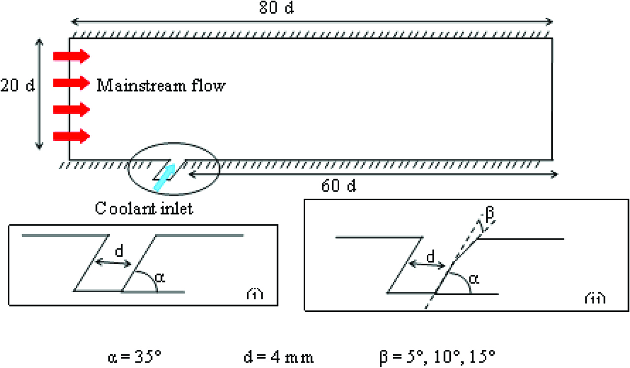
Model for simulation.
Operating parameters
Air was considered as mainstream gas and as the coolant. The mainstream air temperature and the coolant temperature was maintained at 400 K and 300 K respectively. The operating pressure at the inlet was set to 101,325 Pascal and the outlet pressure was set as 0 Pascal. The mainstream velocity of the air was maintained at 10 m/s and the coolant was injected with a velocity of 10 m/s, for a blowing ratio BR of 1.3 for validation purposes. The turbulent kinetic energy and the turbulent dissipation rate was set to 1 m2/s2 and 1 m2/s3 respectively. For other studies, four different blowing ratios of 0.5, 1, 1.5 and 2 were analysed.
SIMPLE scheme was selected for the pressure-velocity coupling and for spatial discretization the second order upwind scheme was selected for momentum, turbulent kinetic energy and turbulent dissipation rate. The y + value was maintained within the bounds of the viscous sublayer throughout the simulations.
The thermophysical properties of air (k, Cp, ρ and ʋ) used in the numerical simulation was obtained from the standard properties of air reported at 1atm [18]. Since the thermophysical properties of air are not constant across the simulated temperature range, the property data was converted into 7th degree polynomial as a function of temperature by curve fitting. The polynomial equations chosen were ensured that the coefficient of determination (r2) was about 0.999 for all cases. The property data are reported in Table 1 for various thermophysical properties.
The 7th degree polynomial is given by eq. (12) where x temperature in Kelvin.
Convergence criteria
The residuals for mass was set to 10–5, energy, momentum and turbulence kinetic energy residuals was set to 10–6. The simulations were set to run for 5000 iterations or until convergence is attained.
Grid dependence study
A mesh independence study was performed, two different mesh sizes were chosen such that the total elements were about 400,000 and 100,000. It was seen that that centreline difference cooling effectiveness for the two meshes were less than 0.5 %.
The velocity in x direction at a location of x/2d = 2.5 is shown in Figure 2 for the two mesh sizes. It can be seen that there is very little change in the velocity data and hence no further refinement was performed. A similar trend is seen the temperature data as shown in Figure 3. Since there is no significant change in the analysed data for the two sizes, all the simulations were carried out with 100,000 elements in order to reduce computational effort.
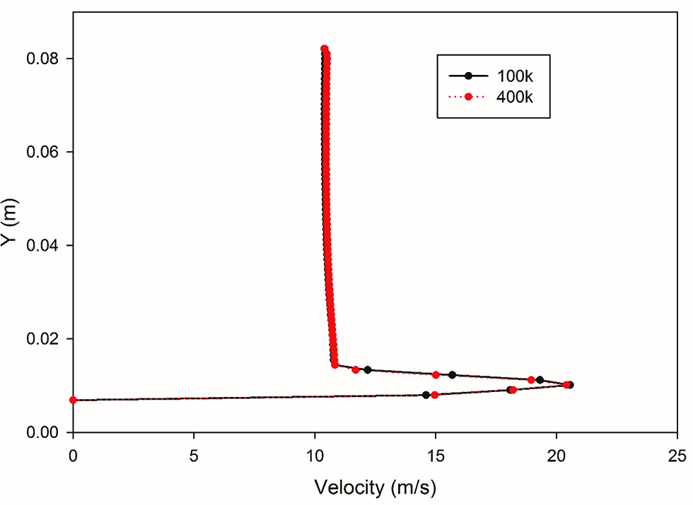
Velocity distribution for two mesh sizes with 100,000 and 400,000 elements.
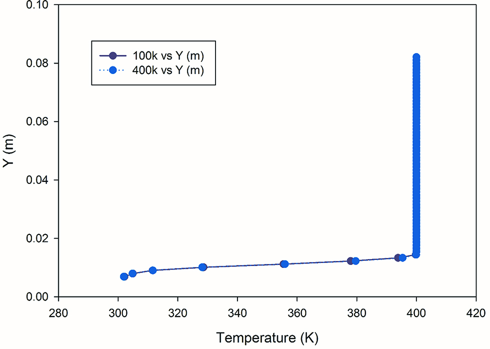
Temperature distribution for two mesh sizes of 100,000 and 400,000 elements.
Validation
The results of the numerical simulation was validated with the data reported from other literature. Figure 4 shows the effectiveness data of the simulation compared with the results reported by Li et al. [17]. It is observed that the results are in close agreement. The temperature data was from the simulation is also in agreement with Zhao et al. [11], the deviation was less than 1.5 %. The x distance from the coolant injection hole is converted to x/2d in order to make non-dimensional for analysis purposes. x/2d is set to zero at the centre of the coolant injection hole.
![Figure 4: Results of the numerical study compared with the results of Li et al. [17].](/document/doi/10.1515/tjj-2019-0046/asset/graphic/j_tjj-2019-0046_fig_004.jpg)
Results of the numerical study compared with the results of Li et al. [17].
Results and discussions
The Figure 5 shows the effect of blowing ratio for a cylindrical hole. The results show that the lowest effectiveness is obtained for BR of 0.5. BR of 1.0 is seen to be the most effective, this is in agreement with the results reported from various literature [3, 8, 15]. It can also be seen with an increase in blowing ratio, the rate of effectiveness decrease downstream of the injection hole increases. This phenomenon is observed in the experimental results reported by Sinha et al. [14]. The higher effectiveness near the injection wall for higher blowing ratio indicates that the coolant jet has detached and has reattached downstream. However at the downstream section, for higher BR the effectiveness is lower since the coolant jet does not fully come into contact with the wall.
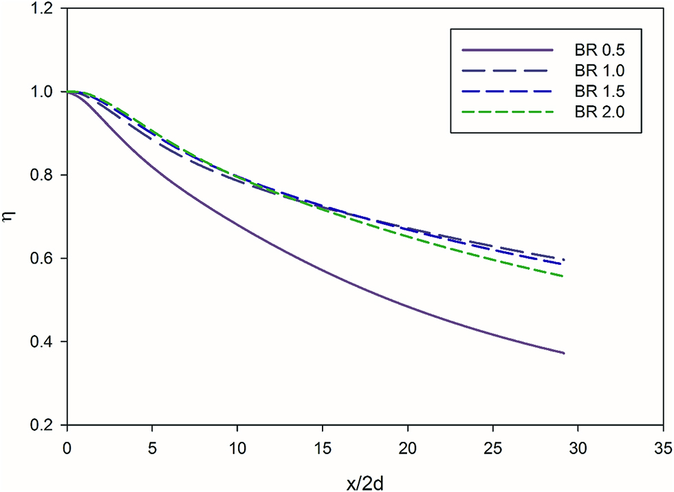
Effect of blowing ratio on cylindrical hole.
The effectiveness at BR of 0.5 rapidly decreases downstream from the injection hole, this is due to the high heat load of the mainstream gas and lower available energy flux.
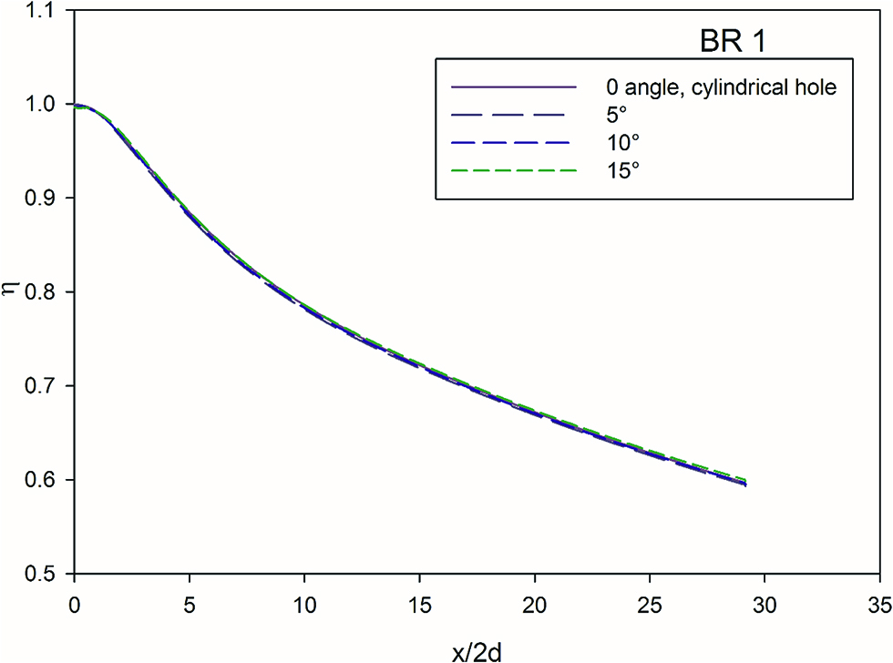
The Figures 6 and 7, indicates the effect of diffusion angle at blowing ratio of 0.5 and 1. At blowing ratio of 0.5 and at a distance x/2d = 5, the effectiveness is higher at higher diffusion angles compared to cylindrical hole, this local increase in effectiveness is due to the better attachment of the jet to the wall. At BR = 1, the effect of hole diffusion angle is negligible. There is very little change in effectiveness at near the coolant injection hole. This phenomenon can be observed in Figure 8 below.

Effect of diffusion angle at BR = 0.5.
Effect of diffusion angle at BR = 1.
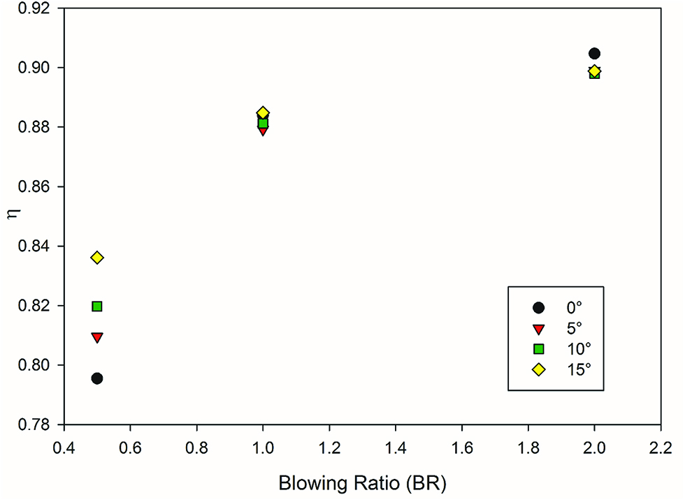
Effect of angle at various blowing ratio at x/2d = 5.
Figure 9 shows effect of diffusion angle at a BR of 2. Similar trends is observed for a BR of 1.5, hence only BR 2 is discussed here. At distance up to x/2d = 15, there is no significant change in the effectiveness for all diffusion angles. There is a slight decrease in effectiveness of about 2 % for all angles compared to cylindrical hole. However this trend is reversed in the downstream section of the injection hole. Form Figure 5 for BR greater than 1, the effectiveness is reduced, for a cylindrical hole, whereas for diffused angle holes here there is an improvement in the effectiveness.
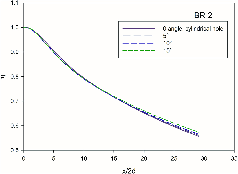
Effect of diffusion angle at BR = 2.
The Figure 10 shows the effect of the angle at BR of 0.5, 1 and 2 at a distance of x/2d = 25 from the injection hole. The phenomenon explained earlier is more evident now. The downstream performance at BR = 0.5 is lower than the cylindrical hole, and is explained in earlier sections. At higher blowing ratios however this is reversed. The hole angle increases the effectiveness downstream due to higher attachment of cooling jet to the wall in downstream sections as the blowing ratio increases. In this case, an increase of 9.8 % at 15° angle of the hole is observed compared to the cylindrical hole.
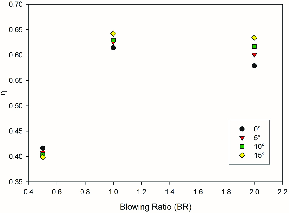
Effect of angle at various blowing ratio at x/2d = 25.
Figure 11 shows the velocity data at x/2d = 5, for a BR of 2. The effect of diffusion angle on the velocity can be visualized. The plot indicated the velocity at x/2d = 5 for a height of 0.02 m from the wall. At higher diffusion angles, the velocity is reduced as compared to the cylindrical hole, this is due to the better attachment of the coolant jet to the wall. This reduction in velocity at higher diffusion angles is observed for all blowing ratios.
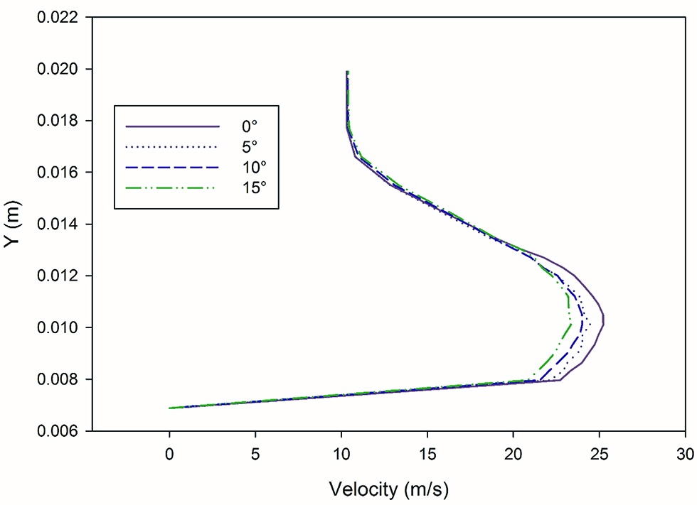
Effect of angle on velocity at x/2d = 5.
In summary, the effect of the angle can be effectively discussed when the test sections can be split into three sections i. e. I from x/2d = 0 to x/2d = 5.0, II from x/2d = 5.1 to x/2d = 20.0 and III for x/2d above 20.1. In section I, at low blowing ratio of 0.5, an increase in the diffusion angle resulted in increased effectiveness, at other blowing ratios of 1, 1.5 and 2, there is no significant change. In section II, the diffusion angles did not have any observable effect on the effectiveness. In section III, at higher blowing ratios, the diffusion whole angles is found to impact the effectiveness. Multiple rows of angled holed at lower blowing ratios could offer better cooling effectiveness.
Conclusion
The effect of angle in a diffused hole film cooling at various blowing ratios was studied numerically and the following key observations were made.
At lower blowing ratios, an increase in the hole angle increased the cooling effectiveness near the injection hole.
At a blowing ratio of 1, increase in diffused hole angle did not have any effect in the cooling effectiveness.
At higher blowing ratios, increase in hole angle resulted in increase in cooling effectiveness downstream of the coolant injection hole. This is in contradiction to the results obtained at blowing ratio of 0.5.
In conclusion, the diffusion angle improves the cooling effectiveness near the injection hole at lower blowing ratio and at downstream sections at higher blowing ratios. In actual practice, typically in a turbine blade there are several rows of cooling holes. Therefore, having holes with angles can be utilized at lower blowing ratios, thereby improving the effectiveness and also reducing the cooling air required resulting in better efficiency.
There is a good scope of future work. The manufacturing feasibility, actual performance, strength of these cooling holes can be studied in great detail.
Thermophysical properties of air.
| Coefficient | Density ρ (kg/m3) | Specific heat Cp (J/kg K) | Thermal Conductivity kair (W/m k) | Kinematic Viscosity ʋ (m2/s) |
|---|---|---|---|---|
| a | 5.0437 | 3462.582 | 0.0715 | −0.001 |
| b | −0.029 | −40.373 | −0.001 | 1.416e-05 |
| c | 8.433e-05 | 0.278 | 8.788e-06 | −9.765e-08 |
| d | −1.172e-07 | −0.010 | −3.447e-08 | 3.668e-10 |
| e | 2.642e-11 | 2.281e-06 | 7.858e-11 | −8.058e-13 |
| f | 1.377e-13 | −2.909e-09 | −1.043e-13 | 1.037e-15 |
| g | −1.680e-16 | 2.003e-12 | 7.476e-17 | −7.232e-19 |
| h | 6.200e-20 | −5.750e-16 | −2.234e-20 | 2.113e-22 |
Nomenclature
- BR
Blowing ratio
- d
Coolant hole diameter
- Cp
Specific heat (J/kg K)
- T
Temperature (K)
- k
Thermal Conductivity (W/mK)
- u
Velocity (m/s)
- Subscripts
- aw
Adiabatic wall
- c
Coolant
- g
Mainstream gas
- Greek Characters
- α
Injection angle (deg)
- β
diffusion angle (deg)
- ρ
Density (kg/m3)
- κ
Turbulent kinetic energy (m2/s2)
- ε
Turbulent dissipation (m2/s3)
- υ
Kinematic viscosity (m2/s)
- η
Cooling effectiveness
References
1. Boyce MP. Gas turbine engineering handbook. USA: Elsevier, 2011.Suche in Google Scholar
2. Han J-C, Dutta S, Ekkad S. Gas turbine heat transfer and cooling technology. Boca Raton, Florida, USA: CRC Press, Taylor and Francis Group, 2012.10.1201/b13616Suche in Google Scholar
3. Krewinkel R. A review of gas turbine effusion cooling studies. Int J Heat Mass Transfer. 2013;66:706–22.10.1016/j.ijheatmasstransfer.2013.07.071Suche in Google Scholar
4. Bogard DG. Airfoil film cooling. Gas Turbine Handb. 2006;4:309–21.Suche in Google Scholar
5. Hu Y, Ji H Numerical study of the effect of blowing angle on cooling effectiveness of an effusion cooling. In: ASME Turbo Expo 2004: Power for Land, Sea, and Air. American Society of Mechanical Engineers, 2004:877–84.10.1115/GT2004-54043Suche in Google Scholar
6. Baldauf SA, Scheurlen M, Schulz A, Wittig S. Correlation of film cooling effectiveness from thermographic measurements at engine like conditions. In: ASME Turbo Expo 2002: Power for Land, Sea, and Air. American Society of Mechanical Engineers, 2002:149–62.10.1115/GT2002-30180Suche in Google Scholar
7. Cerri G, Giovannelli A, Battisti L, Fedrizzi R. Advances in effusive cooling techniques of gas turbines. Appl Therm Eng. 2007;27:692–8.10.1016/j.applthermaleng.2006.10.012Suche in Google Scholar
8. Al-Hemyari M, Hamdan MO, Orhan MF. A numerical analysis of the slot film-cooling effectiveness. In: Advances in Science and Engineering Technology International Conferences (ASET), IEEE, 2018:1–7.10.1109/ICASET.2018.8376813Suche in Google Scholar
9. Ren J, Li X, Jiang H. Conjugate heat transfer characteristics in a highly thermally loaded film cooling configuration with TBC in syngas. Aerospace. 2019;6:16.10.3390/aerospace6020016Suche in Google Scholar
10. Baheri S, Alavi Tabrizi SP, Jubran BA. Film cooling effectiveness from trenched shaped and compound holes. Heat Mass Transfer. 2008;44:989–98.10.1007/s00231-007-0341-9Suche in Google Scholar
11. Wang T, Zhao L. Discussions of some myths and concerned practices of film cooling research. Int J Heat Mass Transfer. 2011;54:2207–21.10.1016/j.ijheatmasstransfer.2010.11.003Suche in Google Scholar
12. Rao PM, Biswal P, Prasad BV. A computational study of mist assisted film cooling. Int Commun Heat Mass Transfer. 2018;95:33–41.10.1016/j.icheatmasstransfer.2018.03.028Suche in Google Scholar
13. Azzi A, Jubran BA. Numerical modelling of film coolingfrom converging slot-hole. Heat Mass Transfer. 2007;43:381–8.10.1007/s00231-006-0115-9Suche in Google Scholar
14. Sinha AK, Bogard DG, Crawford ME. Film-cooling effectiveness downstream of a single row of holes with variable density ratio. J Turbomach. 1991;113:442–9.10.1115/1.2927894Suche in Google Scholar
15. Zhai Y-N, Liu C-L, Yi-Hong H, Zhou Z-X. Investigationon the film cooling performance of diffuser shaped holes with different inclination angles. Int J Turbo Jet-Engines. 2017;34:123–39.10.1515/tjj-2016-0026Suche in Google Scholar
16. Versteeg HK, Malalasekera W. An introduction to computational fluid dynamics: the finite volume method. England: Pearson Education, 2007.Suche in Google Scholar
17. Li X, Wang T. Simulation of film cooling enhancement with mist injection. J Heat Transfer. 2006;128:509–19.10.1115/GT2005-69100Suche in Google Scholar
18. Holman JP Heat transfer, 9th, 2002.Suche in Google Scholar
© 2020 Gandhi and Sivan, published by De Gruyter
This work is licensed under the Creative Commons Attribution-NonCommercial-NoDerivatives 4.0 International License.