Design and analysis of a complementary split ring resonator (CSRR) metamaterial based antenna for wideband application
-
Sikder Sunbeam Islam
 ,
Touhidul Alam
,
Touhidul Alam

Abstract
In this article, a compact complementary split ring resonator (CSRR) based double-negative (DNG) metamaterial antenna is presented for wideband (4.49 GHz–21.85 GHz) wireless application. The antenna is incorporated with a DNG metamaterial patch: 50Ω microstrip feed line and partial ground plane. The antenna shows measured fractional bandwidth of 131.81% with a compact size of 0.37λ×0.37λ×0.01λ. The commercially available finite integration technique (FIT)-based simulation software, computer simulation technology (CST) microwave studio was adopted to investigate the performance of the proposed antenna. Several parametric studies were performed to investigate the effect of key structural parameters on antenna performances. The double-negative characteristics of the metamaterial were investigated as well.
1 Introduction
With the recent advent of artificial metamaterials, there has been a lot of interest in the field of microwave applications. These artificial materials have become popular in the field of electromagnetic due to some exotic properties that are not naturally found, such as inverted Snell’s law, negative refractive index, etc. Therefore, these unusual properties of metamaterial are being used in many important applications now, such as for antenna design, electromagnetic absorption reduction, invisibility cloaking, etc. [1–5].
Recently, metamaterial has played a promising role in the field of antenna design for enhancing gain, bandwidth, directivity, and radiation efficiency. Arrays of metamaterial or multi-band metamaterial have become potential studies for researchers. Not enough studies are found in the literature on such approaches, for example, a near zero refractive index (NZRI) metamaterial-based antenna was proposed for X-band by Zhou et al. [6] but they added two metasurface layers over the main antenna, and their antenna size was 70×72mm2. A single-negative (SNG) metamaterial-based antenna was claimed by Ntaikos et al. [7] but their antenna resonated in the S- and C-band only. Islam et al. [8] showed an antenna that contains superstrate metasurface, but its patch dimension was 70×80mm2 and maximum gain was 5.28 dBi. Ullah et al. [9] demonstrated an NZRI metasurface based antenna, but it was applicable for L-band, S-band, and C-band only, and its patch dimension was 34×28mm2. Moreover, Dissanayake et al. presented an L-slot wideband antenna [11], which achieved an impedance bandwidth of 5.87 GHz (5.5–11.37 GH) with an antenna size of 50×50 mm2. Rmili et al. proposed a wideband double-sided printed dipole antenna for C and X band [12]. Although the antenna achieved a fractional bandwidth of 87.6%, the antenna dimension was quite large at 75×50 mm2.
In this study, a double-negative metamaterial-based planar antenna is proposed. The proposed antenna displays an impedance bandwidth of 17.36 GHz. The metamaterial characteristics and measured result of the antenna is presented. In the basic design, a complementary split ring resonator (CSRR) metamaterial was used as a patch that was followed by a feed line and a short ground in the back. The basic idea behind it is that due to the coupling effect, the radiating element of the antenna is sensitive to the presence of the CSRR. The CSRR as a double-negative (DNG) metamaterial effectively affects radiating characteristics of the antenna. Moreover, a conducting ground was backed to the substrate with a slight shortened pattern to broaden its working bandwidth due to a coupling effect. However, the proposed antenna was confined in the 25×25mm2 dimension.
2 Methodology
The design of the proposed metamaterial-based patch antenna has been done using a widely used computer simulation technology (CST) microwave studio. The CSRR double-negative metamaterial was designed first, and its characteristics were checked. The inner and outer radius of the outer ring were 4 mm and 5 mm. Similarly, the inner and outer radius of the inner ring were 2.77 mm and 3.77 mm. The gap between the two rings of the CSRR was 0.33mm. The magnetic resonance was strongly affected by its geometric parameters. The design parameter and the schematic view of the proposed DNG CSRR metamaterial unit cell structure is given in Figure 1A.
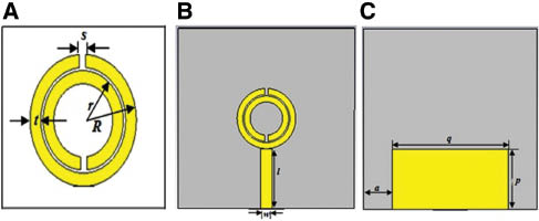
(A) The geometry of the metamaterial, (B) the geometry of the antenna (front view), (C) Rear view of the antenna.
The magnetic resonance is induced by the splits at the rings and by the gaps between the inner and outer rings in this type of metamaterial. Figure 1B and 1C show the front and back view of the antenna geometry. Based on the commonly used mathematical formulation of conventional rectangular patch antennas, the basic derivation of the antenna size was followed [10]. However, the length and width of the proposed slotted patch antenna were optimized using the CST microwave studio. The metamaterial based antenna was printed on a square-shaped FR-4 substrate with dielectric constant of 4.5, dielectric loss-tangent of 0.002, side length and width of 25 mm, and thickness of 1 mm. In the front side, the CSRR metamaterial was placed as a patch in the design that was followed by a copper feed line. In the back side of the antenna, a conducting partial ground was used in the design. All of the design parameters are given in Table 1. All the design parameters have a thickness of 0.035mm.
Design specifications of the metamaterial antenna.
| Design parameters | Value (mm) |
|---|---|
| a | 5 |
| l | 10 |
| p | 9.5 |
| q | 20 |
| R | 5 |
| r | 3.77 |
| s | 0.6 |
| t | 1 |
| w | 2 |
For characterizing the metamaterial, the CSRR unit cell structure was positioned between two waveguide ports of negative, positive of x-axis, and excited by the transverse electromagnetic (TEM) wave. The perfect electric conductor (PEC) boundary and perfect magnetic conductor (PMC) boundary were defined in the rest of the axes. The transient solver with hexahedral mesh has been used for antenna simulation. Normalized impedance has been set to 50Ω. Simulation has been run for the frequency range of 1 to 15 GHz for the metamaterial analysis and 1to 22 GHz for the antenna performance investigation. The effective medium parameters permittivity and permeability were calculated from the simulated S-parameters using the method mentioned by Dissanayake et al. [11].
3 DNG metamaterial characterization
Figure 2A displays the numerical result of the reflection coefficient (S11). The seven major resonances are seen in Figure 2A at 3.42 GHz, 5.046 GHz, 6.79 GHz, 8.65 GHz, 11.54 GHz, 12.76 GHz, and 14.18 GHz that is below -10dB. The two rings of the metamaterial are like the LC circuits, where the usual metal rings are responsible for creating the inductance (L), and the split of the rings are accountable for creating the capacitance (C). These rings are excited by a time varying magnetic field parallel to the axis of the rings, the electrostatic field is induced in the split and inductive current in the rings, and then results in exchange by resonant energy.
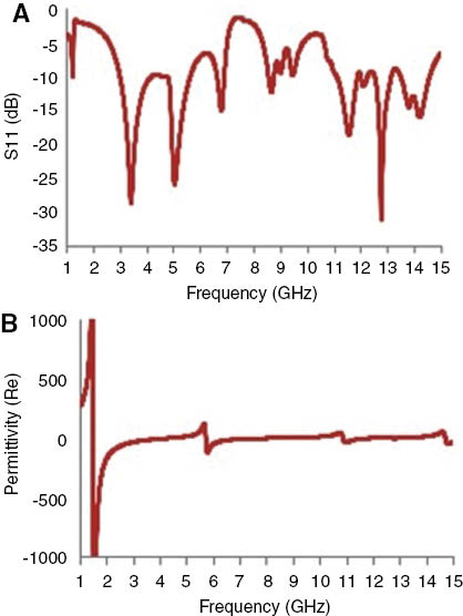
(A) Simulated reflection coefficient (S11) in dB, (B) real magnitude of permittivity.
By increasing the side and length of the rings, the inductance can be increased, which leads to a decrease in the LC resonance frequency. Similarly, by increasing the split, the capacitance can be reduced, which leads to an increase in the LC resonant frequency.
Figure 2B shows the real magnitude of permittivity against the frequency for the metamaterial unit cell. Figure 3A and B presents the consecutive real value of permeability and the real magnitude of refractive index against the frequency for the metamaterial. It is observed from Figures 2 and 3 that the four resonance points 3.42 GHz, 6.79 GHz, 11.54 GHz, and 12.76 GHz are where the metamaterial is found to have DNG characteristics among the four points. The detail characteristics data of the unit cell are presented in Table 2 for the aforementioned frequencies.
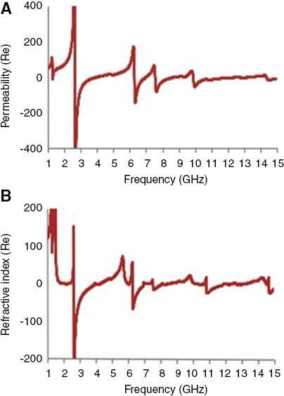
(A) Real magnitude of permeability, (B) real magnitude of refractive index.
Double-negative properties of the unit cell.
| Frequency (GHz) | Permittivity | Permeability | Refractive index |
|---|---|---|---|
| 3.42 | -17.42 | -17.33 | -17.39 |
| 6.79 | -10.40 | -10.71 | -10.84 |
| 11.54 | -5.58 | -5.69 | -5.70 |
| 12.76 | -0.57 | -1.25 | -0.92 |
4 Antenna performance analysis
In order to observe the physical phenomenon of the proposed antenna, the current distributions at different frequencies are analyzed. The surface current distribution obtained from simulation software for different frequencies is shown in Figure 4. A stronger surface current distribution is observed along the CSRR based metamaterial and near feed line. It is observed that the CSRR structure is an important factor for wideband.
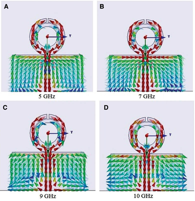
Surface current distribution of the proposed antenna at (A) 5GHz, (B) 7GHz, (C) 9GHz, and (D) 10 GHz.
To investigate the effects of the antenna parameters, a parametric study has been performed using electromagnetic simulation software. In the investigation, except from the parameter of interest, the parameters remain constant. First, the reflection coefficient has been studied with different types of SRR structure, shown in Figure 5. From Figure 5, it is shown that the circular CSRR structure has achieved the maximum impedance bandwidth. Moreover, a parametric study was performed on the effect of SRR gap position. The gap position is 0°, 45°, 90°, and 120° to investigate the antenna performance, presented in Figure 6. It is observed from Figure 6 that the antenna shows maximum impedance bandwidth at a SRR gap of 0° positions. To show the effect of the substrate thickness of the proposed antenna, a parametric study has been done, which is depicted in Figure 7. It is shown in Figure 7 that the antenna shows better impedance bandwidth at the substrate thickness of 1mm than 0.8 mm and 1.6 mm. The microstrip feed line width plays an important role for proper impedance matching. That is why a parametric study has been performed to ensure better impedance matching, which is presented in Figure 8. It is clearly observed from Figure 8 that for the value of w=1.5 mm; the antenna shows good impedance matching.
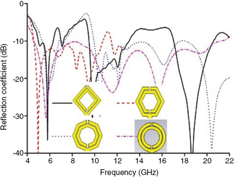
Reflection coefficient for different types of SRR.
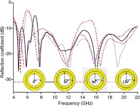
Reflection coefficient for different position of the SRR gap.
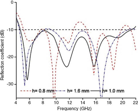
Reflection coefficient for different values of substrate height.
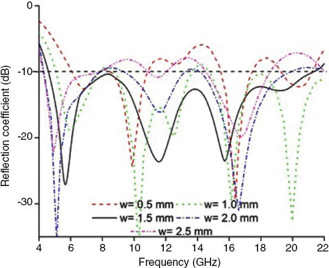
Reflection coefficient for different values of microstrip feed line width.
Figure 9 shows the input impedance characteristic of the proposed antenna for different values of p. The values of p change from 8.5 mm to 10.5 mm at 0.5 mm steps. When p=8.5 mm, then the antenna shows two impedance bands of 3.95 GHz (5.8–9.75 GHz) and 4.3 GHz (14.5–18.8 GHz). When the value increased to 9.5 mm, the antenna achieved wide impedance bandwidth of 17.36 GHz (4.49–21.85 GHz). After that increasing the value, the impedance bandwidth becomes narrower than the previous one. That is why the optimum value of p is set to 9.5 mm.
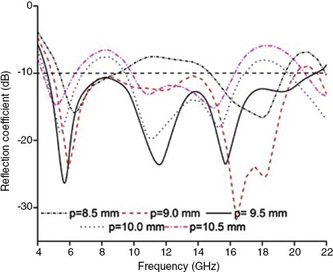
Reflection coefficient for different values of ground pane width “p.”
The fabricated prototype of the proposed antenna is illustrated in Figure 10. The antenna is fabricated on commercially available FR-4 substrate material with thickness of 1 mm, permittivity of 4.6. The voltage standing wave ratio (VSWR), phase and Smith chart measurement of the proposed antenna are performed using the Agilent E8362C vector network analyzer. The measured and simulated reflection coefficient of the proposed antenna is shown in Figure 11.
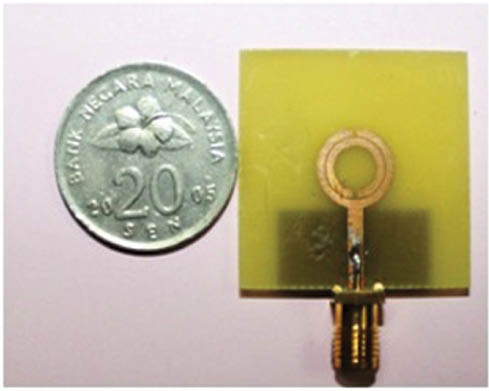
Prototype of the proposed antenna.
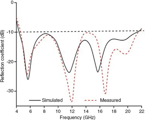
Measured and simulated reflection coefficient of the antenna.
The measured 10dB reflection coefficient bandwidth covers the frequency range from 4.49 to 21.85 GHz. As the ground plane decrease in size, the antenna characteristics are affected by the SMA connector. That is why a little deviation is observed in measured and simulated value of the reflection coefficient. The impedance matching of the proposed antenna is observed using the Smith chart, presented in Figure 12. From the measured Smith chart, it is shown that the antenna achieved better impedance matching. The corresponding electronic dimension of the proposed antenna is 0.37λ×0.37λ×0.01λ; here, λ refers to the lower-end frequency that meets the -10-dB reflection coefficient. The antenna shows fractional bandwidth of 131.81% at the lower frequency. Moreover, the compactness and wideband characteristics of the antenna have been determined using an index term bandwidth dimension ratio (BDR). This index term indicates how much operating bandwidth (in percentage) can be provided per electrical area unit. The equation is presented in (1). The calculated BDR of the proposed antenna is 941.5291.
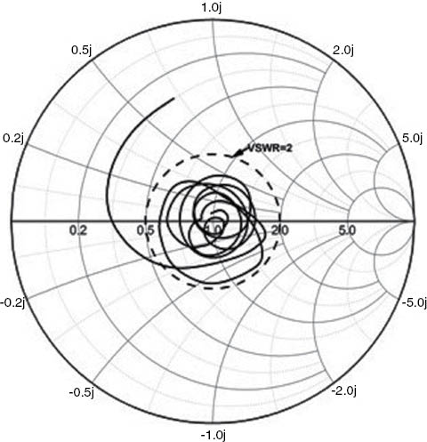
Measured smith chart of the antenna.
For a complete study of the far field, performance of the proposed CSRR based antenna inside an anechoic chamber is illustrated in Figure 13. Radiation patterns are measured at three frequencies: 5 GHz, 7 GHz, and 10 GHz. Figure 14 depicts the measured radiation patterns of the proposed antenna. Figure 14 shows that the proposed antenna achieved a near about omnidirectional radiation pattern for H-plane at the presented frequencies. In addition, the realized gain and the radiation efficiency of the proposed is depicted in Figure 15. The antenna achieved the maximum 92.52% of radiation efficiency and 6.034dBi of realized gain. The minimum radiation efficiency is 64.80%, and gain is 1.05 dBi.
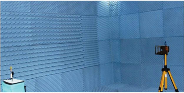
Radiation pattern measurement in the anechoic chamber.
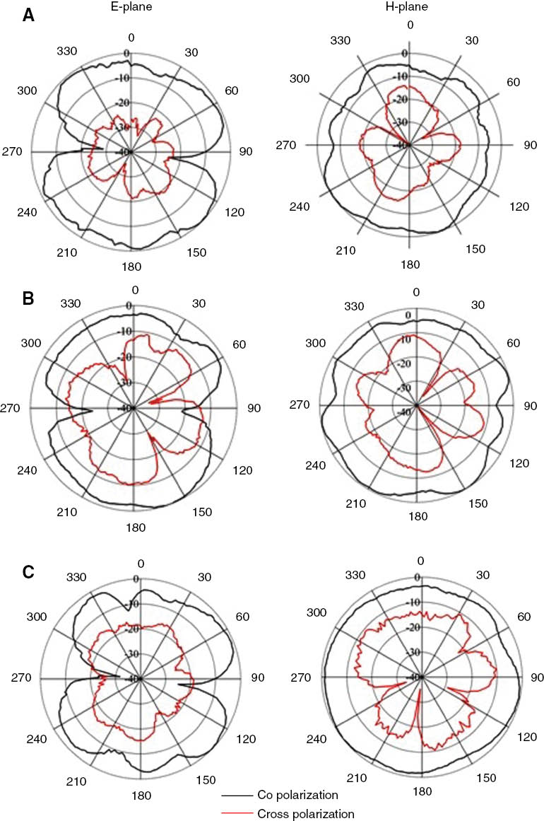
Measured radiation pattern of the proposed antenna at (A) 5GHz, (B) 7GHz, (C) 10 GHz.
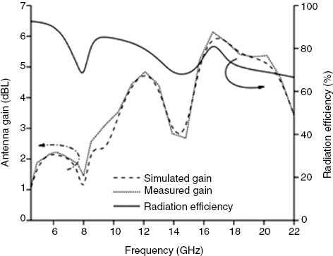
Radiation efficiency and realized gain of the proposed antenna.
5 Conclusions
A CSRR based DNG metamaterial antenna was presented for wideband application. Antenna performance analysis was performed by both simulation and experiments, where the antenna achieved wide impedance bandwidth of 17.36 GHz (4.49–21.85 GHz) and the bandwidth dimension ratio of 941.53 with small size of 25×25×1 mm3. Moreover, the antenna exhibited 4.05dBi of average gain, an omnidirectional H-plane radiation pattern, and a satisfactory level of radiation efficiency within the entire operating band. The proposed antenna was also very promising to be implemented for wideband wireless applications.
Acknowledgments
This work is supported by the Ministry of Education Malaysia (MOE) under Grant no. FRGSTOPDOWN/2014/TK03/UKM/01/1.
References
[1] Faruque MRI, Islam MT, Misran, N. Med. Eng. Phys. 2011, 33, 646–652.10.1016/j.medengphy.2010.12.004Search in Google Scholar PubMed
[2] Wu B-I, Wang W, Pacheco J, Chen X, Grzegorczyk T, Kong JA. Prog. Electromagn. Res. 2005, 51, 295–328.10.2528/PIER04070701Search in Google Scholar
[3] Sikder SI, Mohammad RIF, Mohammad TI. Materials 2015, 8, 4790–4804.10.3390/ma8084790Search in Google Scholar PubMed PubMed Central
[4] Islam SS, Faruque MRI, Islam MT. Appl. Phys. A 2014, 116, 723–733.10.1007/s00339-014-8549-2Search in Google Scholar
[5] Lee H-M, Lee H-S. Prog. Electromag. Res. C 2013, 34, 111–121.10.2528/PIERC12091804Search in Google Scholar
[6] Zhou H, Pei Z, Qu S, Zhang S, Wang J, Duan Z, Ma H, Xu Z. IEEE Antennas Wireless Propag. Lett. 2009, 8, 538–541.10.1109/LAWP.2009.2018710Search in Google Scholar
[7] Ntaikos DK, Bourgis NK, Yioultsis TV. IEEE Antennas Wireless Propag. Lett. 2011, 10, 963–966.10.1109/LAWP.2011.2167309Search in Google Scholar
[8] Islam MT, Ullah MH, Singh MJ, Faruque MRI. Materials 2013, 6, 3226–3240.10.3390/ma6083226Search in Google Scholar PubMed PubMed Central
[9] Ullah MH, Islam MT, Faruque MRI. Materials 2013, 6, 5058–5068.10.3390/ma6115058Search in Google Scholar PubMed PubMed Central
[10] IEEE Standard Letter Designations for Radar Frequency Bands, https://standards.ieee.org/findstds/standard/521–2002.html (accessed March 22, 2014).Search in Google Scholar
[11] Dissanayake T, Karu PE. IEEE Trans. Antennas Propag. 2008, 56, 1183–1187.10.1109/TAP.2008.919221Search in Google Scholar
[12] Rmili H, Floc’h J, Khaleghi A. Electron. Lett. 2006, 42, 1076–1077.10.1049/el:20061948Search in Google Scholar
©2017 Walter de Gruyter GmbH, Berlin/Boston
This article is distributed under the terms of the Creative Commons Attribution Non-Commercial License, which permits unrestricted non-commercial use, distribution, and reproduction in any medium, provided the original work is properly cited.
Articles in the same Issue
- Frontmatter
- Original articles
- Surface modification of polyimide fibers by oxygen plasma treatment and interfacial adhesion behavior of a polyimide fiber/epoxy composite
- Influence of micro- and nanofiller contents on friction and wear behavior of epoxy composites
- Sintering temperature-microstructure-property relationships of alumina matrix composites with silicon carbide and silica additives
- A study of the effect of chemical treatments on areca fiber reinforced polypropylene composite properties
- Studying the nonlinear properties and strain-rate sensitivity of SiC short fiber-reinforced Al matrix composites
- Effects of precure cycle on tensile and dynamical mechanical properties of carbon/benzoxazine laminates
- Microstructure and wear resistance of composite coating by laser cladding Ni60A/B4C pre-placed powders on Ti-6Al-4V substrate
- Elevated electrochemical corrosion behavior of a B4C/Al neutron absorber by shot peening modification
- The influence of microstructure geometry on the scale effect in mechanical behaviour of heterogeneous materials
- Design and analysis of a complementary split ring resonator (CSRR) metamaterial based antenna for wideband application
- Numerical study on the interfacial behavior of Mg/Al plate in explosive/impact welding
- The effect of calcium salts on air-void structure in air-entrained concrete – a statistical and simulated study
- Optimisation of the ceramic-like body for ceramifiable EVA-based composites
- Elasto-plastic analysis and finite element simulation of thick-walled functionally graded cylinder subjected to combined pressure and thermal loading
- Performance of a transfer beam with hybrid reinforcement of CFRP bars and steel bars under reversed cyclic loading