Surface modification of polyimide fibers by oxygen plasma treatment and interfacial adhesion behavior of a polyimide fiber/epoxy composite
-
Xuyang Sun


Abstract
Oxygen plasma was used to enhance the surface behavior of polyimide (PI) fibers and PI fiber-reinforced epoxy composites were prepared in our present work. The effects of plasma treating times on the surface properties of PI fiber and the interfacial adhesion of PI fiber/epoxy composites were investigated. Surface chemical composition, surface morphologies and surface free energy of the fibers were characterized by X-ray photoelectron spectroscopy, scanning electron microscopy and dynamic contact angle analysis, respectively. The results suggest that some oxygen functional groups were introduced onto PI fiber surfaces, and the surface roughness of fibers was enhanced. Resultantly, the surface free energy of fibers and the interfacial adhesion of composites were improved by the oxygen plasma treatment. The interlaminar shear strength of the composites increased to 70 MPa when the fibers were treated for 10 min, which proved good interfacial adhesion properties.
1 Introduction
Since the first polyimide (PI) fiber was prepared by Koton in the Soviet Union in the 1970s, high-performance PI fibers with a unique aromatic-chain structure have attracted much attention from researchers around the world [1–8]. PI fibers possess excellent thermal and mechanical properties, high radiation and corrosion resistance and outstanding dielectric properties, which endow them with great potential applications as reinforcements for the fabrication of advanced composite materials used in aerospace, protective garments, electric cables and the military [3, 4]. However, the research on PI fiber-reinforced composite materials has never been reported before. This is because the commercial products of PI fibers are scarcely obtained except for P84 fiber with a tensile strength of only about 0.5 GPa. Fortunately, based on our previous work, the batch production of PI fibers with high strength and modulus has been successfully achieved by Jiangsu Shino New Materials and Technology Co. Ltd, which provides us with convenience to concentrate on the fabrication of the PI fiber-reinforced composite materials.
Nevertheless, similar as those typical organic fibers like poly-p-phenylene benzobisoxazole (PBO) and armos fibers, it is found that PI fibers also show poor wettability and weak interfacial interaction with the resin matrix because of their smooth surface and low surface energy [9, 10]. Consequently, the mechanical properties of the composite materials are limited. So study on surface modifications of PI fibers is necessary in order to improve the surface affinity and the interfacial interaction between PI fibers and resin matrix. It is well known that PI has a strong chemical resistance due to its rigid imide ring structure, and it can only be degraded in alkali solution of high concentration [11, 12]. As a result, much research has been done to ameliorate the surface activity of PI membranes and PI fibers by alkali solution treatment [13, 14]. But the subsequent necessity on huge amounts of water leads to an abominable waste of resources and energy, which limits its commercial practicality. Among other surface modification techniques such as plasma, radiation and coupling agents, the low-temperature plasma treatment expresses a desirable practicability with its rapid treatment time, ensuring high producing efficiency, low energy consumption and the lowest decrease in fiber strength and thermal stability [15]. It has been widely used in the surface modification of carbon fibers, PBO fibers and aramid fibers, and substantial research reported that large amounts of active groups could be introduced onto the fibers’ surface [16–19].
So in this work, we focus on the surface modification of PI fibers with high strength and high modulus by employing a plasma treatment in oxygen atmosphere and the fabrication of PI-reinforced epoxy (PI/EP) composite materials by using such modified PI fibers. The physical and chemical variations in the fiber surface were investigated by using scanning electron microscopy (SEM), X-ray photoelectron spectroscopy (XPS) and dynamic contact angle analysis (DCAA). Furthermore, the influential mechanisms of the plasma treatment that corresponded to those variations of the fiber status are discussed according to the surface free energy theory.
2 Materials and methods
2.1 Materials
The PI fibers used in this study were fabricated by Jiangsu Shino New Materials and Technology Co. Ltd (Jiangsu, China) via the two-step spinning technology by copolymerization of 3,3′,4,4′-biphenyltetracarboxylic dianhydride, p-phenylenediamine and a third monomer containing quinazolinone moiety. The diameter, the density, the tensile strength and the tensile modulus of the PI fibers are 11 μm, 1.46 g cm-3, 3.0 GPa and 120 GPa, respectively. Epoxy resin diglycidyl ester of aliphatic cyclic (Tianjin Jindong Chemical Factory, China, epoxy value 0.85), diluter butyl glycol diglycidyl ether (Tianjin Jindong Chemical Factory) and hardener diethyl methyl benzene diamine (Lonza, Switzerland) were used to prepare the uncured resin for preparing PI/EP composites.
2.2 Plasma treatment
An inductive coupling radio frequency (40 KHz) generator was used to obtain the oxygen plasma. The oxygen plasma treatment system mainly consists of a plasma cleaning instrument (Diener Prep2), a vacuum pump and an oxygen cylinder. The plasma cleaning instrument can control the operating pressure, the input power and the treatment time. Vacumming lasted for 10 min before the oxygen was delivered to the chamber of the plasma cleaning instrument, and the operating pressure was maintained at 30 Pa. The polyimide fibers were fixed on a glass pane and then put into the chamber to be treated by oxygen plasma for different durations (5, 10, 15 and 20 min), under a power of 200 W. After that, the treated fibers were immediately sealed with a preservative film for future use.
2.3 Preparation of the PI/EP composites
The untreated and plasma-treated PI fiber-reinforced epoxy composites were made by compression molding technique. The fibers got sufficiently coated with the uncured epoxy resin by passing through it. Then the obtained prepreg was put into an oven at 50°C for 30 min as a defoaming process. After that, the composite was cured in the oven by compression molding at 110°C for 2 h, 150°C for 3 h and 180°C for 3 h. All composite samples were about 6 mm in width and 2 mm in thickness. The volume fraction of fiber in the composites was controlled at about 50%.
2.4 Characterization
2.4.1 X-ray photoelectron spectroscopy
The XPS measurement was conducted with an ESCALAB 250 spectrometer (Thermo Electron Corporation) equipped with a monochromatic Al Kα X-ray source and a magnetic lens system that yields high spatial resolution and high sensitivity. The base pressure in the sample chamber was controlled at 2×10⁻¹⁰ mbar or lower during each measurement. The spectra were collected at a take-off angle of 45°.
2.4.2 Scanning electron microscopy
The morphologies of single-fiber surface and the topographies of composites’ interlaminar shear failure were observed by SEM (FE-SEM-4700, Hitachi, Japan) operating at an accelerating voltage of 20 kV. All the samples were coated with gold about 5 nm prior to the measurements. The magnification of the images was set at 5000× and 1000×.
2.4.3 Single-fiber tensile strength analysis
The tensile strength of the PI fibers was tested on a monofilament tensile machine (YG001A-1) at room temperature. The length of the fiber samples was 20 mm, and the testing speed was 10 mm min-1. The value of each tensile strength was the average of 20 samples.
2.4.4 Dynamic contact angle analysis
The dynamic contact angles between the PI fibers and the testing liquids were measured through a dynamic contact angle analyzer DCAT21 (Datephysics, Germany). The fiber samples were cut into about 1 cm in length, and four of them were fixed symmetrically to a resin cylinder connected to the microbalance. Then the fibers were immersed into the testing liquid by raising the stage at a set speed of 0.05 mm s-1 up to 5 mm. The values of the contact angles were obtained by the testing system directly, and the surface free energy was calculated through the following equations [20]:
where θ is the dynamic contact angle, γl is the surface tension of the testing liquid,
2.4.5 Interlaminar shear strength testing
The interlaminar shear strength testing (ILSS) of the composites was measured on a universal testing machine (SANS CMT 41041) with the test mode of three-point short-beam bending according to GB3357-82. The width of the testing specimen was 6 mm, and the thickness was 2 mm. The ratio of the span to the specimen thickness was 5:1. The specimens were tested at a cross-head speed of 1 mm min-1. Every ILSS outcome for each specimen was the average of five values. The ILSS was calculated by the following equation:
where τs is the ILSS, Pb is the maximum compressive load at fracture in Newton, b is the width of the specimen in millimeters, and h is the thickness of the specimen in millimeters.
3 Results and discussion
3.1 The surface chemical composition of the PI fibers under different duration of oxygen plasma treatment
The oxygen plasma treatment can introduce various oxygen-based polar functionalities to the polymer surfaces [21]. An XPS analysis was applied to appraise the surface elemental composition of the PI fibers, and the results are shown in Table 1. For the untreated fibers, the surface carbon and oxygen concentrations were 80.27% and 17.29%, and the ratio of oxygen to carbon atoms (O1S/C1S) was 0.22. After an oxygen plasma treatment for 5 min and 10 min, the surface carbon concentrations decreased to 77.98% and 74.16%, respectively, while the surface oxygen concentrations increased to 20.75% and 23.44%, respectively. And the ratio of O1S/C1S increased to 0.27 and 0.32 for each. However, increasing time of the plasma treatment from 10 min to 15 min or 20 min would further decrease the oxygen concentration from 23.44% to 22.44% or 21.80%, respectively. Compared with the untreated fibers, all the plasma-treated fibers had higher surface oxygen concentrations and O1S/C1S ratios. Concentration of nitrogen did not change obviously before and after the oxygen plasma treatment.
The surface composition of the PI fibers under different treatment times.
| Plasma treatment | Relative atomic concentration (at.%) | Proportion | |||
|---|---|---|---|---|---|
| C1S | O1S | N1S | O1S/C1S | N1S/C1S | |
| Untreated | 80.27 | 17.29 | 2.44 | 0.22 | 0.03 |
| 5 min | 77.98 | 20.75 | 1.27 | 0.27 | 0.02 |
| 10 min | 74.16 | 23.44 | 2.40 | 0.32 | 0.03 |
| 15 min | 75.62 | 22.44 | 1.94 | 0.30 | 0.03 |
| 20 min | 76.42 | 21.80 | 1.78 | 0.29 | 0.02 |
To investigate the alteration of the functional groups on PI fiber surface, a deconvolution analysis of C1S peaks was carried out. The C1S XPS spectra of the original and the plasma-treated PI fiber surfaces are shown in Figure 1. The surface after plasma treatment had five carbon-containing groups with binding energies of 284.6 eV (-C-C-), 285.4 eV (-C-N), 286.1 eV (-C-O), 287.8 eV (-C=O) and 289.1 eV (-COO), and the calculated concentrations of the groups are listed in Table 2 [22–27]. For the original surface, the concentrations of -C-C-, -C-N, -C-O, -C=O and -COO groups were 77.1%, 14.3%, 2.6%, 6.0% and 0.0%, respectively. The -C-O, -C=O and -COO concentrations of fiber surfaces treated for 10 min increased to their maximum values of 11.3%, 6.5% and 5.8% and then decreased to 5.2%, 4.7% and 2.7% after being treated for 20 min. These results suggest that oxygen-containing functional groups have been introduced onto the surface of PI fibers via the oxygen plasma treatment, as shown in Figure 1F. And the surface PI molecular chain might be changed to poly(amic acid) via a ring opening process through the plasma treatment. The introduction of the oxygen-containing functional groups with proper duration of plasma treatment could improve the wettability of fiber surfaces and modify the adhesive behavior between the fiber and the matrix [28]. But if the treatment time went too long, the fiber surfaces would be over-etched, leading to the peel-off of polar groups [25, 29].

The C1S core-level spectra: (A) untreated; (B) 5 min; (C) 10 min; (D) 15 min; (E) 20 min; (F) schematic images of the PI fibers after plasma treatment.
The concentration of the different carbon groups on the polyimide surface.
| Plasma treatment | Relative area corresponding to different chemical bonds (%) | ||||
|---|---|---|---|---|---|
| -C-C-&-C-H (%) | -C-N (%) | -C-O (%) | -C=O (%) | -COO (%) | |
| Untreated | 77.1 | 14.3 | 2.6 | 6.0 | 0.0 |
| 5 min | 66.7 | 14.0 | 9.6 | 5.1 | 4.6 |
| 10 min | 62.5 | 13.9 | 11.3 | 6.5 | 5.8 |
| 15 min | 71.2 | 14.2 | 7.3 | 4.2 | 3.2 |
| 20 min | 73.4 | 14.1 | 5.2 | 4.7 | 2.7 |
3.2 The surface morphology and the single-fiber tensile strength of the polyimide fibers under different oxygen-plasma-treatment time
An important influence of plasma treatment is surface-etching, which can roughen the polymer surfaces [30]. The effect of oxygen plasma treatment on PI fiber surface morphology was observed by SEM. A comparison of the SEM images between the original and the treated PI fibers is presented in Figure 2. It can be seen that the surface of the untreated PI fiber is relatively clean and smooth with little grooves (Figure 2A). After being treated for 5 min (Figure 2B), a few visible streak flaws and spots were formed on the fiber surface, which would lead to a slight decrease in the mechanical properties of the PI fibers. Then substantial amounts of spots, protrusions and depressions can be seen on the fiber surface that was treated for 10 min, and the fiber surfaces’ roughness changed dramatically. Carrying on treatment to 15 min or 20 min would even destroy them. Figure 3 shows the mechanical properties of the PI fibers under influence of treatment time. The increment of treating duration from 5 min to 10 min, 15 min and 20 min would cause the percentage decrease in tensile strength as 0.0%, 2.1%, 14.4% and 16.5%, respectively. It demonstrates that the PI fibers could maintain excellent mechanical properties when the treatment time is within 10 min.

The SEM images of PI fiber under different treatment time: (A) untreated; (B) 5 min; (C) 10 min; (D) 15 min; (E) 20 min.

Tensile strength of the polyimide fiber.
The increase of fiber surface roughness contributes to better surface wettability and mechanical interlocking effect, which can enhance the interfacial adhesion between fibers and matrix [30, 31]. Fibers’ tensile strength decreased slowly when the treatment time was within 10 min, but extended treatment would lead to excessive roughness of the fiber surfaces. Subsequently, fibers’ mechanics performance would be decreased significantly, and the interfacial properties would be damaged owing to stress concentrations [25]. The overetching could result in destruction of the fiber surfaces, and the polar groups on them might be peeled off from the fiber, similar tendency as which has also been proved by XPS analysis.
3.3 The surface free energy of the polyimide fibers under different oxygen-plasma-treatment time
The DCAA is an important method to investigate the wetting behavior between liquids and fibers. The surface free energy that significantly affects the wettability can be calculated via the contact angle test [20, 32]. The values of the contact angles and the surface free energy of the PI fibers as functions of the plasma treatment time are shown in Figure 4.

The contact angle and the surface free energy of the polyimide fibers.
Figure 4 shows that the untreated PI fibers possessed a contact angle of 80.59° in water and 56.54° in glycol, while the surface free energy was 31.13 mJ m-2. After the oxygen plasma treatment, their contact angles both in water and in glycol decreased, and the surface free energy increased correspondingly. When the PI fibers were treated for 10 min by oxygen plasma, the contact angles in both water and glycol reached their minimum values – 50.43° and 39.85°. Meanwhile, the surface free energy reached its maximum value at 50.92 mJ m-2. This can be explained by the generating of polar functional groups on the PI fiber surface through the oxygen plasma’s treatment as shown by the XPS measurements (Table 2), which effectively enhanced the surface affinity of the PI fiber. And the plasma treatment can also deepen the surface roughness of fiber surface as illustrated by the SEM images (Figure 2), which together enhanced the surface free energy [10, 18].
However, the surface free energy decreased to 39.05 mJ m-2 and 35.61 mJ m-2, respectively, when increasing the plasma treatment time to 15 min and 20 min. This was attributed to the destruction of fiber surfaces (Figure 2) and thus the decrement in the concentration of polar groups on the fiber surfaces (Table 2) [25].
3.4 The influence of oxygen-plasma-treatment time on the ILSS of the PI/EP composites
The ILSS is an effective method for estimating the interfacial adhesion between fibers and a matrix [33, 34]. The effect of oxygen plasma treatment time on the ILSS of epoxy composites reinforced by unidirectional polyimide fiber is illustrated in Figure 5. It can be seen that all the PI/EP composites with treated fibers exhibit higher ILSS values than those with untreated fibers as reinforcement. And the ILSS increased first with the increasing treatment duration and then decreased along with further increment of treating time beyond 10 min. When the oxygen plasma treatment lasted for 15 min or 20 min, the ILSS values of the composites declined to 65.31 MPa or 63.50 MPa, respectively. This tendency is in accordance with the above results of XPS, SEM and surface free energy. When the treatment time was <10 min, the oxygen plasma could introduce oxygen-containing groups onto the polyimide fiber surfaces and enlarge the surface roughness, both of which played positive roles in enhancing interfacial adhesion of the composites. Nevertheless, when the polyimide fibers were treated more than 10 min, excess plasma etching would reduce the interfacial adhesion [25]. This could be used to explain why the ILSS increased when the plasma treatment time varied from 0 to 10 min, while it decreased when the plasma treatment time went beyond 10 min.

The ILSS of the PI/EP composites.
The fracture morphologies of the PI/EP composites are presented in Figure 6. The differences between these two images are obvious. For composite reinforced by untreated PI fibers (Figure 6A), the fibers were pulled out from the epoxy matrix with little resin clinging to the surface. This indicated that destruction of the composite took place on the interface between fiber and matrix. For the composite reinforced by oxygen-plasma-treated PI fiber, there was more epoxy resin adhering to the fibers, and a lot of fibers were embedded into the resin, which implied that the primary failure occurred in the matrix. So it was proved that the oxygen plasma treatment could significantly improve the interfacial adhesion between PI fibers and epoxy resin.
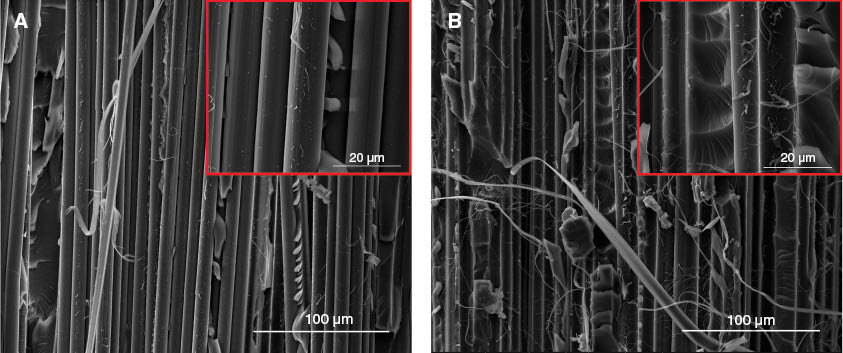
SEM images of the fractured PI/EP composites: (A) untreated, (B) treated 10 min.
4 Conclusion
In summary, the effects of oxygen plasma treatment on surface chemistry, morphology and surface free energy of PI fibers as well as the interfacial interaction of PI/EP composites were studied in the present work. Experiments showed that the surface roughness of the PI fibers could be enhanced, and oxygen-containing functional groups (e.g. -C=O and -COO-) could be introduced onto the fiber surfaces by the oxygen plasma treatment, resulting in a significant improvement in the surface energy and affinity of the PI fibers. Moreover, to the best of our knowledge, this is the first study on surface modification of PI fibers by using a plasma treatment, and it showed that such a treatment would dramatically increase the performance of PI-reinforced composite materials.
Acknowledgments
This work was supported by the National Key Basic Research Program of China (973 Program, project no. 2014CB643600), the Foundation Research Project of Jiangsu (Natural Science Foundation for Distinguished Young Scholars, BK20140006) and the Fundamental Research Funds for the Central Universities of China (project no. ZY1408).
References
[1] Koton MM, Frenkel SYA, Adrova NA. 1977, SU215399-A.Search in Google Scholar
[2] Konton MM, Florinsky FS, Frenkel SY, Korzhavin LN, Pushkina TP, Prokopchuk NR. 1980, Pat GB2025311.Search in Google Scholar
[3] Niu H, Qi S, Han E, Tian G, Wang X, Wu D. Mater. Lett. 2012, 89, 63–65.10.1016/j.matlet.2012.08.088Search in Google Scholar
[4] Niu H, Huang M, Qi S, Han E, Tian G, Wang X, Wu D. Polymer 2013, 54, 1700–1708.10.1016/j.polymer.2013.01.047Search in Google Scholar
[5] Neuber C, Schmidt HW, Giesa R. Macromol. Mater. Eng. 2006, 291, 1315–1326.10.1002/mame.200600256Search in Google Scholar
[6] Perepelkin KE, Dresvyanina EN, Pakshver EA. Fibre Chem. 2008, 40, 266–269.10.1007/s10692-008-9050-5Search in Google Scholar
[7] Rajendiran TV, Anbuselvan C. Asian J. Chem. 2010, 22, 4985–4993.Search in Google Scholar
[8] Hiroshi I, Taro I, Tsutomu T. J. Photopolym. Sci. Tech. 2013, 26, 291–295.10.2494/photopolymer.26.291Search in Google Scholar
[9] Zhang YH, Huang YD, Liu L, Cai KL. Appl. Surf. Sci. 2008, 254, 3153–3161.10.1016/j.apsusc.2007.10.081Search in Google Scholar
[10] Liu D, Chen P, Chen M, Liu Z. Surf. Coat. Tech. 2012, 206, 3534–3541.10.1016/j.surfcoat.2012.02.033Search in Google Scholar
[11] Yang S, Wu D, Qi S, Cui G, Jin R, Wu Z. J. Phys. Chem. B 2009, 113, 9694–9701.10.1021/jp900755cSearch in Google Scholar PubMed
[12] Mu S, Wu Z, Qi S, Wu D, Yang W. Mater. Lett. 2010, 64, 1668–1671.10.1016/j.matlet.2010.05.005Search in Google Scholar
[13] Mu S, Wu Z, Wang Y, Qi S, Yang X, Wu D. Thin Solid Films 2010, 518, 4175–4182.10.1016/j.tsf.2009.12.004Search in Google Scholar
[14] Zhan J, Wu D, Qi S, Wu Z. J. Nanosci. Nanotechnol. 2010, 10, 987–993.10.1166/jnn.2010.1891Search in Google Scholar
[15] Jia C, Chen P, Wang Q, Li B, Chen M. J. Appl. Polym. Sci. 2012, 125, 433–438.10.1002/app.35631Search in Google Scholar
[16] Ma K, Wang B, Chen P, Zhou X. Appl. Surf. Sci. 2011, 257, 3824–3830.10.1016/j.apsusc.2010.12.074Search in Google Scholar
[17] Chen P, Zhang C, Zhang X, Wang B, Li W, Lei Q. Appl. Surf. Sci. 2008, 255, 3153–3158.10.1016/j.apsusc.2008.09.014Search in Google Scholar
[18] Jia C, Chen P, Liu W, Li B, Wang Q. Appl. Surf. Sci. 2011, 257, 4165–4170.10.1016/j.apsusc.2010.11.190Search in Google Scholar
[19] Wang J, Chen P, Liu W, Li H, Jia C, Lu C, Wang B. J. Appl. Polym. Sci. 2011, 121, 2804–2811.10.1002/app.33847Search in Google Scholar
[20] Wu S, J. Polym. Sci. Polym. Symp. 1971, 34, 19–30.10.1002/polc.5070340105Search in Google Scholar
[21] Park JM, Kim DS, Kim SR. J. Colloid Interf. Sci. 2003, 264, 431–445.10.1016/S0021-9797(03)00419-3Search in Google Scholar
[22] Qi S, Wu Z, Wu D, Yang W, Jin R. Polymer 2009, 50, 845–854.10.1016/j.polymer.2008.12.010Search in Google Scholar
[23] Li H, Liang H, He F, Huang Y, Wan Y. Surf. Coat. Tech. 2009, 203, 1317–1321.10.1016/j.surfcoat.2008.10.042Search in Google Scholar
[24] Hema V, Wang Y, Ahmad AA, Philip AJ, Peter SMA. Chem. Mater. 2001, 13, 1647–1655.10.1021/cm000930hSearch in Google Scholar
[25] Chen M, Liu D, Chen P, Liu Z, Ding Z. Surf. Coat. Tech. 2012, 207, 221–226.10.1016/j.surfcoat.2012.06.073Search in Google Scholar
[26] Zhu L, Wang C, Qiu Y. Surf. Coat. Tech. 2007, 201, 7453–7461.10.1016/j.surfcoat.2007.02.012Search in Google Scholar
[27] Yung KC, Zeng DW, Yue TM. Appl. Surf. Sci. 2001, 173, 193–202.10.1016/S0169-4332(00)00884-9Search in Google Scholar
[28] Hegemann D, Brunner H, Oehr C. Nucl. Instrum. Meth. B 2003, 208, 281–286.10.1016/S0168-583X(03)00644-XSearch in Google Scholar
[29] Morra M, Occhiello E, Garbassi F. Surf. Interface Anal. 1990, 16, 412–417.10.1002/sia.740160186Search in Google Scholar
[30] Sanchis MR, Blanes V, Blanes M, Garcia D, Balart R. Eur. Polym. J. 2006, 42, 1558–1568.10.1016/j.eurpolymj.2006.02.001Search in Google Scholar
[31] Kang HM, Kim NI, Yoon TH. J. Adhes. Sci. Technol. 2002, 16, 1809–1823.10.1163/156856102320396157Search in Google Scholar
[32] Papakonstantinou D, Amanatides E, Mataras D. Plasma Process. Polym. 2007, 4, S1057–S1062.10.1002/ppap.200732405Search in Google Scholar
[33] Liu Y, Yang J, Xiao H, Qu C, Feng Q, Fu S, Yasuhide S. Compos. Part B-Eng. 2012, 43, 95–98.10.1016/j.compositesb.2011.04.037Search in Google Scholar
[34] Park SJ, Seo MK, Lee JR. J. Colloid Interf. Sci. 2003, 268, 127–132.10.1016/S0021-9797(03)00718-5Search in Google Scholar
©2017 Walter de Gruyter GmbH, Berlin/Boston
This article is distributed under the terms of the Creative Commons Attribution Non-Commercial License, which permits unrestricted non-commercial use, distribution, and reproduction in any medium, provided the original work is properly cited.
Articles in the same Issue
- Frontmatter
- Original articles
- Surface modification of polyimide fibers by oxygen plasma treatment and interfacial adhesion behavior of a polyimide fiber/epoxy composite
- Influence of micro- and nanofiller contents on friction and wear behavior of epoxy composites
- Sintering temperature-microstructure-property relationships of alumina matrix composites with silicon carbide and silica additives
- A study of the effect of chemical treatments on areca fiber reinforced polypropylene composite properties
- Studying the nonlinear properties and strain-rate sensitivity of SiC short fiber-reinforced Al matrix composites
- Effects of precure cycle on tensile and dynamical mechanical properties of carbon/benzoxazine laminates
- Microstructure and wear resistance of composite coating by laser cladding Ni60A/B4C pre-placed powders on Ti-6Al-4V substrate
- Elevated electrochemical corrosion behavior of a B4C/Al neutron absorber by shot peening modification
- The influence of microstructure geometry on the scale effect in mechanical behaviour of heterogeneous materials
- Design and analysis of a complementary split ring resonator (CSRR) metamaterial based antenna for wideband application
- Numerical study on the interfacial behavior of Mg/Al plate in explosive/impact welding
- The effect of calcium salts on air-void structure in air-entrained concrete – a statistical and simulated study
- Optimisation of the ceramic-like body for ceramifiable EVA-based composites
- Elasto-plastic analysis and finite element simulation of thick-walled functionally graded cylinder subjected to combined pressure and thermal loading
- Performance of a transfer beam with hybrid reinforcement of CFRP bars and steel bars under reversed cyclic loading