Influence of a locally variable mold temperature on injection molded thin-wall components
-
Christopher Fischer
 ,
Ariane Jungmeier
,
Ariane Jungmeier

Abstract
Regarding injection-molding of semi-crystalline thermoplastics, controlling mold temperature and, therefore, the polymer melt’s cooling conditions can significantly affect component properties. In this research, an innovative dynamically tempered mold technology with different temperature zones is investigated, which will allow the production of thin-wall components with locally different component properties. First results show that due to influencing inner component properties, significant differences in optical and mechanical component properties can be achieved.
- Abbreviations
- Et
N/mm2
tensile modulus
- PA 6
–
polyamide 6
- ph
bar
holding pressure
- σm
N/mm2
tensile strength
- Te
°C
ejection temperature
- Tmass
°C
mass temperature
- Tm
°C
mold temperature
- Ts
°C
solidification temperature
- tcooling
s
cooling time
- tcycle
s
cycle time
- theating
s
heating time
- tin
s
injection time
- tph
s
holding pressure time
- vin
mm/s
injection speed
1 Introduction
With the demand for product miniaturization being decisively determined by the microelectromechanical system industry, components in the field of microtechnology have become increasingly important in recent years [1]. Here, micro components made of plastic, with typical weights in the range of a few milligrams and dimensions in the sub-millimeter range down to the lower micrometer range, are particularly important because of the comparatively low production costs, especially in the areas of biotechnology and medical technology [2].
Due to the small sample cross-sections, during the injection molding of micro and thin-wall components high cooling rates of the polymer melt occur. This can lead to limitations in the mold filling due to a fast solidification of the melt [3]. In order to allow a complete mold filling, an adaptation of the process control by means of an increase in the injection speed, the mold temperature or the mass temperature has been established. In particular, an increase in the mold temperature can lead to more distinct internal properties (for example higher degree of crystallinity, coarser spherulitic structure, formation of thermally preferred crystal modification, etc.) owing to the reduction of the cooling rate of the polymer melt and, for example a corresponding lower nucleation rate during the crystallization process [4], [5], [6]. By means of influencing the mentioned internal properties, resulting external properties (for example mechanical, optical, tribological, etc.) can be influenced. For semicrystalline materials, an increase in the degree of crystallinity is associated with an increase in stiffness and strength as well as a reduction in the elongation at break [7]. Regarding different crystal modifications, influences on mechanical properties could have been shown. Therefore, regarding polyamide 6 (PA 6), as a material with medium crystallization kinetics and two main crystal modifications (α and γ), it is known that components with a higher α-content exhibit a higher stiffness than components with a higher γ-content at the same degree of crystallinity [8]. In addition to the mechanical behavior of a given material, internal properties can also influence tribological component properties. For components in the macroscopic range, it was shown that a distinct spherulitic structure with a high degree of crystallinity has the lowest wear characteristics taking into account the influence of the tribological system [9], [10], [11], [12]. Recent researches have shown comparable effects also for semicrystalline micro components [13]. In addition, orientations can have higher modulus of elasticity, higher stretching stresses and lower elongation stresses.
Different research shows that internal properties (for example higher degree of crystallinity, coarser spherulitic structure, formation of thermally preferred crystal modification, etc.) and external properties (for example mechanical, optical, tribological, etc.) of small components differ from those of conventional macroscopic components [14], [15], [16], [17], [18]. Because of the relatively fine structures and lower degrees of crystallization, compared to macroscopic components, microstructures exhibit less favorable mechanical properties under comparable processing conditions. A targeted influencing of the internal properties by a reduction in the cooling rate of the polymer melt (for example by an increase in the mold temperature or by the use of low-temperature conductive mold materials) can contribute to a significant improvement in the mechanical properties of the micro and thin-wall components. Currently, existing temperature control concepts aim at a primary homogeneous temperature distribution over the entire cavity length to produce parts with homogenous properties. The aim of the present paper is to investigate the influence of segmented temperature areas within the cavity to produce a component with locally different and defined properties.
2 Dynamic tempering concepts
An increase in mold temperature can, for example be realized by means of a dynamic temperature control of the mold (Figure 1). In the case of conventional dynamic tempering systems, the mold is first heated within the material-specific solidification temperature range. After filling the cavity during the injection step, the mold is cooled below the ejection temperature. The higher mold temperature during the injection process leads to a lower cooling rate of the polymer melt. Thus, the formation of internal properties can be influenced in addition to the better filling behavior [12].
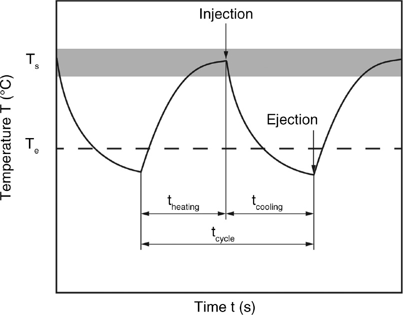
Mold temperature profile during dynamic temperature control (theating, heating time; tcooling, cooling time; tcycle, cycle time; Ts, solidification temperature; Te, ejection temperature).
Currently, various dynamic temperature control systems are used in industry. The heating methods are primarily based on temperature control by media (e.g. oil, water, gaseous CO2) or electrical heating elements (e.g. induction, infrared, ceramic heating elements). Novel water-based dynamic temperature control strategies have short cycle times using tempering channels located close to the cavity. Here, for example plastic gear wheels with homogenized internal properties could be produced [19]. The comparatively low maximum tool temperature of approximately 180°C is particularly disadvantageous. The dynamic temperature control with oil is one of the established methods in industry, whereby the low heat capacity compared to water results in slower heating rates. CO2 temperature control systems are using gaseous CO2 for heating [20]. Here, CO2 first gets heated outside the cavity and then is being transported inside the cavity. Tempering by means of induction leads to inhomogeneous heating in non-planar mold geometries and overheating of the mold in external inductors [19]. Infrared radiators may also result in inhomogeneous heating in the case of non-planar geometrical shapes, since undercuts are generally not uniformly irradiated. In addition, the efficiency is comparatively low due to the reflective steel surfaces of the injection molds [21], which is why special coatings often have to be used. Ceramic heating elements are distinguished by a comparatively low heating energy with a short heating time and, thus, enable an efficient heat input [21]. Furthermore, heating ceramics allow maximum temperatures of up to 300°C. The cooling of dynamic temperature control concepts is primarily realized by means of liquid media. Here, the use of water or oil is industrially common. The achievable cooling rates in the cooling by means of water can achieve a maximum of 10–18 K/s [15], [22]. Due to the lower heat capacity, low cooling rates are usually achieved by means of oil. In addition to water and oil, liquid CO2 can also be used as a cooling medium [20].
3 Materials and methods
3.1 Dynamic mold and tempering concept with segmented heating ceramics
The mold concept presented in this article was designed and built by the companies Ypsomed AG, Burgdorf, Switzerland and gwk Gesellschaft Wärme Kältetechnik mbH, Meinerzhagen, Germany in cooperation with the Institute of Polymer Technology. The heating of the dynamically tempered mold is realized by means of segmented electrical heating ceramics. For this purpose, four heating ceramics are arranged below the cavity region for each (ejector and nozzle) side at a distance of 2 mm; the temperature can be set separately in a temperature range from 25°C to 300°C. Figure 2 shows an infrared image of the cavity side whereby the two upper ceramics and the two lower ceramics are tempered to the same temperature and, therefore, two different temperature zones can be measured. Furthermore, the mold concept is illustrated.
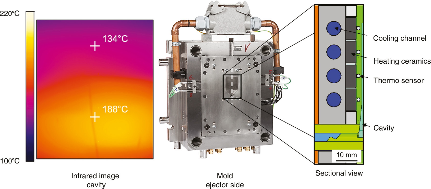
Infrared image of the tempered cavity area; tool concept for segmented dynamic temperature control of thermoplastic thin-wall components; CAD-sectional view.
The temperature control is realized by means of an integrat evolution (gwk Gesellschaft Wärme Kältetechnik mbH, Meinerzhagen, Germany). The integrated high performance mold inserts with ceramic power heaters and close-to-cavity cooling are responsible for the highly dynamic temperature control. Independent from the temperature of the main mold, they control the temperature profile of each individual cavity. In addition to the specification of the respective heating ceramic temperature, the dynamic temperature system allows a setting of the heating power to achieve a defined heating rate. Process control is handled by the central controller of the heating unit, which simultaneously ensures a uniform temperature of the mold. The ceramic high performance heater is located 2 mm behind the cavities. Therefore, a rapid heating at comparatively low energy expenditure can be realized. The start of the cooling phase is initiated by a machine signal. The cooling is realized by cooling channels (surface distance to the cavity is 10 mm, Figure 2) by means of water. Thus, a short cooling phase can be ensured. Furthermore, the water flow rate can be set separately to synchronize the resulting cooling rates of the nozzle and ejector side. After the end of the cooling phase, the mold opens and the next cycle starts.
3.2 Material, specimen and processing
A PA 6 (Ultramid B3K, non-nucleated) (BASF SE, Ludwigshafen, Germany) was used for the investigations, which allows a clear influence of internal properties due to temperature changes because of medium crystallization kinetics [23]. As test specimens, rectangular thin-wall plates with dimensions of 38×35×0.55 mm3 (length×width×thickness) were injection molded by means of an Allrounder 370 U (Arburg) (screw diameter of 15 mm). Relevant injection molding parameters are shown in Table 1.
Relevant injection molding parameters.
| Mass temperature Tmass (°C) | 265 |
| Injection speed vin (mm/s) | 100 |
| Injection time tin (s) | 0.2 |
| Holding pressure ph (bar) | 1200 |
| Holding pressure time tph (s) | 10 |
| Ejection temperature Te (°C) | 25 |
For the present investigations, the set temperature of the two lower heating ceramics (close to the gate) was chosen at 190°C, also compare Figure 2. The set temperature of the two upper heating ceramics was chosen at 135°C. The maximum mold temperature of 190°C was chosen based on internal DSC measurements, after which the material’s crystallization peak is measured at 190°C (cooling velocity 10 K/min). Along with an isothermal holding time of 10 s, it is thus guaranteed that the crystallization takes place isothermally. To avoid mold damage and to achieve a primarily homogenous temperature distribution within each area, the temperature difference was set to 55°C. Here, the maximum temperature difference of 55°C can be achieved if two heating ceramics are simultaneously heated (two heating ceramics close to the gate and two heating ceramics close to the component’s end).
3.3 Component characterization
3.3.1 Component photography, transmission, morphology and degree of crystallinity
In order to assess the optical properties, besides a frontal component photography the transmission was measured by means of the spectrometer UV/VIS Lambda 18 (PerkinElmer, Waltham, MA, USA) in a wavelength range of 250–850 nm. For consideration of the morphology, a 10 μm thin section was taken along the flow direction in the middle of the injection molded component and analyzed at 45° linearly polarized transmitted light by means of the microscope Axio Imager.M2 (Carl Zeiss AG, Oberkochen, Germany). To evaluate the degree of crystallinity, the band ratio for the wave numbers 1200 (crystalline band) to 1124 (amorphous band) was determined over the cross-section of the component by means of the infrared spectroscope Nicolet 6700 FT-IR (Thermo Electron Corporation, Madison, WI, USA). The measurements were carried out using 10 μm thin sections taken transversely to the flow direction. According to [23], the wavenumber ratio is suitable for assessing the degree of crystallinity. Therefore, a higher ratio represents a higher degree of the respective crystal phase. Figure 3 exemplarily shows the evaluation of the FT-IR bands.
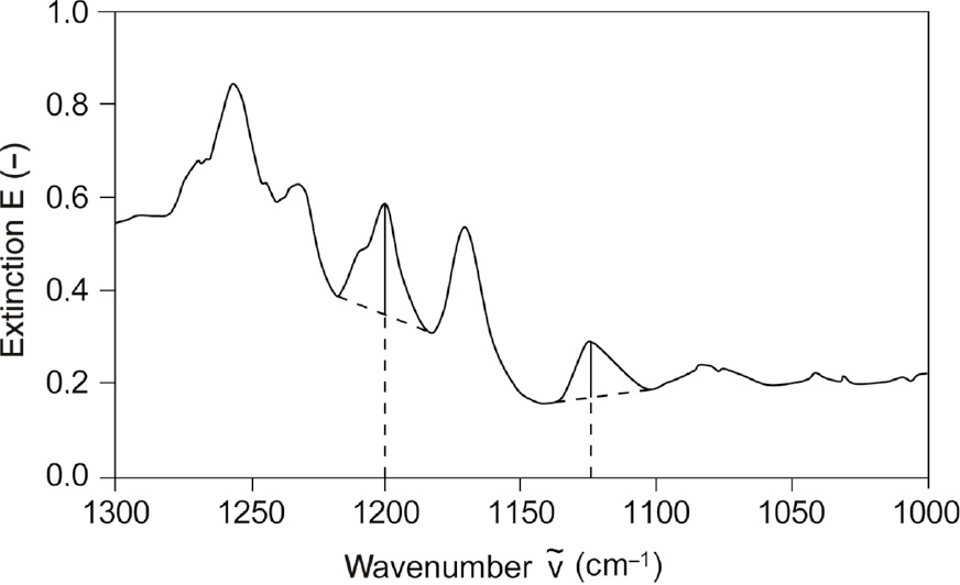
Evaluation of the crystalline and amorphous band by FT-IR.
The evaluation positions for transmission, morphology and degree of crystallinity are located 9 mm (135°C mold temperature) or 21 mm (190°C mold temperature) from the component end (Figure 4). Thus, it is possible that measurements are performed in a component area manufactured at primarily homogenous temperature distributions.
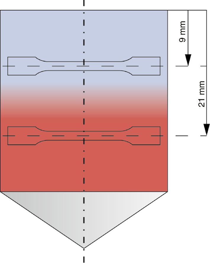
Position for evaluation of transmission, morphology, degree of crystallinity, tensile modulus and tensile strength (blue, cold temperature zone; red, warm temperature zone).
3.3.2 Mechanical properties
For the determination of the mechanical parameters tensile modulus, tensile strength and yield strain, tensile bars were prepared from the different temperature ranges transversely to the flow direction (Figure 4). The dimensions were scaled on 1–8 based on the campus tensile bar (DIN EN ISO 527). Therefore, a tensile bar with a tensile test area of 10×4 mm2 results. The drying was carried out in a vacuum drying cabinet at 23°C. Here, the low temperature was chosen to avoid post-crystallization. The tensile tests were carried out according to DIN EN ISO 527. Therefore, five tensile bars were tested using an Instron 5948 MicroTester (Instron GmbH, Darmstadt, Germany) at standard climate.
4 Results
4.1 Transmission, morphology and degree of crystallinity
The results of the transmission measurements, as well as a component photograph, are depicted in Figure 5. The component photograph shows that there are optical differences in the components. Accordingly, the component region, which was produced at 190°C, has a greater tendency towards opacity, which can indicate a more distinct spherulitic structure. The optical differences of the different component regions are confirmed by the transmission measurements. Therefore, the component regions which crystallize within the 135°C zone show a significantly higher transmission in the optically visible wavelength range (380–780 nm).
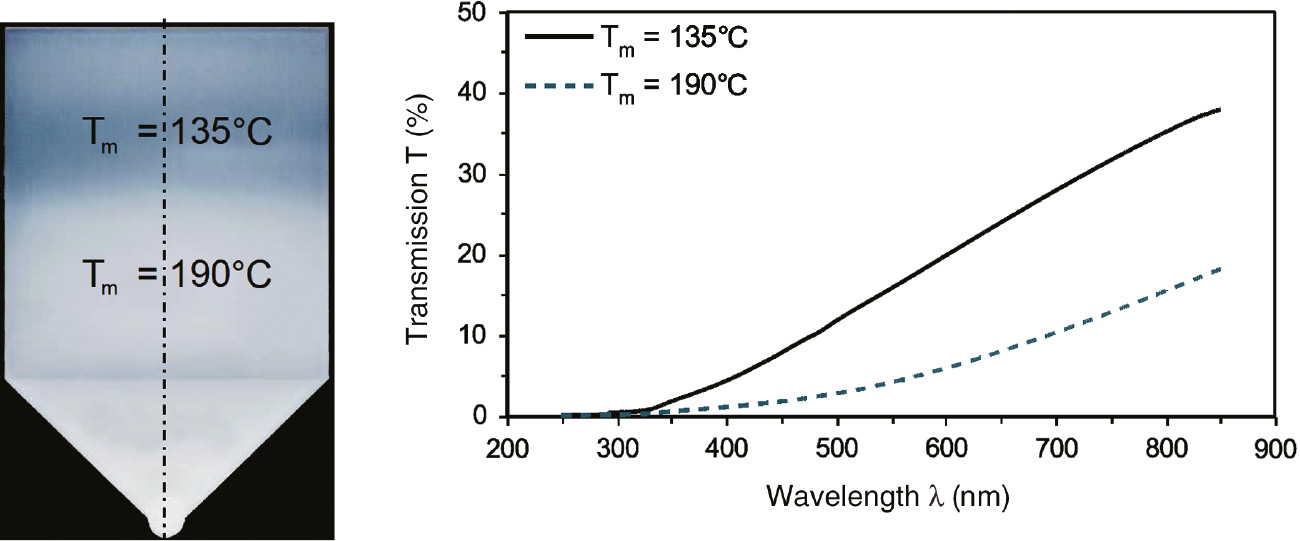
Component photography and measured transmission of an injection-molded component produced at different mold temperature zones (Tm) 135°C and 190°C.
Figure 6 shows the resulting morphologies of the component regions produced at different mold temperature zones.
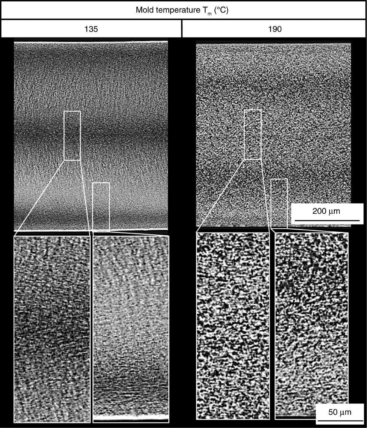
Morphology of an injection-molded plate produced at a mold temperature zone (Tm) of 135°C (left) and 190°C (right).
At 190°C, in comparison to 135°C, a significantly coarser spherulitic structure can be seen over the entire cross-section. Furthermore, the component’s morphology produced at higher temperatures does not have an oriented skin layer. The differences in the morphology can be explained by the different cooling rates of the polymer melt during the injection process. Accordingly, due to the slow cooling and the resulting lower nucleation rate, larger spherulitic structures are formed at 190°C. In addition, the high temperature leads to a relaxation of the oriented skin layer.
Figure 7 shows the band ratio for the wavenumbers 1200 (crystalline band) to 1124 (amorphous band) over the component’s cross-section for the qualitative assessment of the degree of crystallinity.
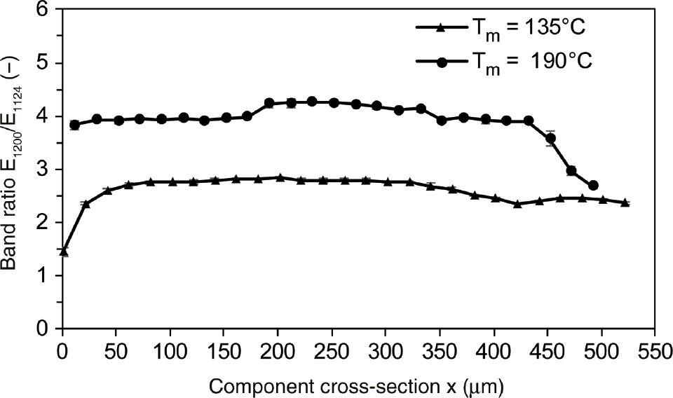
Band ratio E1200/E1124 over the component’s cross-section of an injection-molded plate produced at a mold temperature zone (Tm) of 135°C and 190°C.
Based on the results, it can be shown that the component region, which was produced at 190°C, reaches a higher band ratio over the entire specimen cross-section than the 135°C component region. In the skin region, both test body sections show the lowest characteristic values. This could be attributed to the locally highest cooling rate. The higher degrees of crystallization are again attributed to the slow cooling rate of the melt, resulting in more perfect crystals, which can be reflected in the degree of crystallinity.
4.2 Mechanical properties
Figure 8 shows the results for the tensile modulus and tensile strength. The results show that the 190°C component regions achieve significantly higher tensile modulus and tensile strength characteristics. Accordingly, an increase in tensile modulus of 29% and an increase in tensile strength of 12% are measured. Regarding the yield strain, a decrease of 11% can be measured with increasing temperature. The differences in the resulting component properties are attributed to the different internal component properties. Therefore, the coarser spherulitic structure and the higher degree of crystallinity increase the mechanical properties.
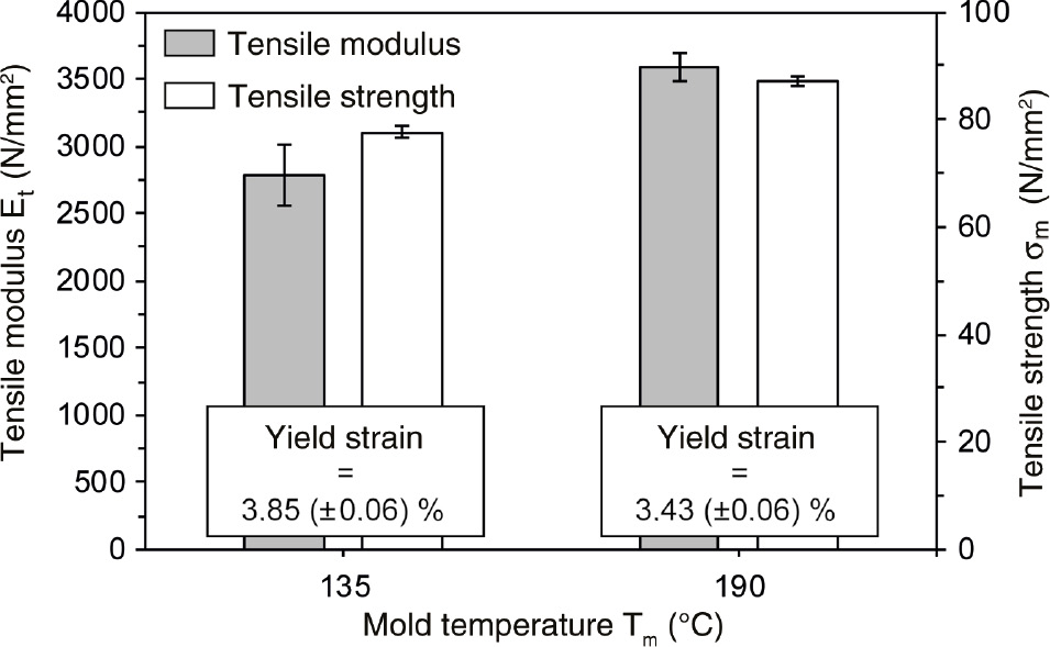
Mechanical characteristics tensile modulus, tensile strength and yield strain of injection-molded plates produced at a mold temperature zone (Tm) of 135°C and 190°C.
5 Conclusion
In this paper, the influence of a locally different cooling behavior during the injection molding process of semicrystalline thermoplastics was investigated. Within the scope of the present investigations, a novel, dynamically tempered mold temperature concept with segmented heating ceramics was developed to produce parts with locally different properties to allow for new areas of application. Therefore, thin-wall plates made of PA 6 were injection-molded at locally different mold temperature zones, whereby the mold temperature zones were chosen with 190°C and 135°C according to the material’s crystallization temperature range. The components were analyzed in terms of their inner properties as well as the resulting optical and mechanical properties to show the influence of locally different temperature zones on resulting inner and, as a consequence, global component properties. To determine inner component properties, the morphology as well as the degree of crystallinity were measured. For mechanical component properties, tensile tests in the respective component area were performed.
First results show that for PA 6, as a material with relatively slow crystallization kinetics, a locally different temperature can influence the inner component properties. Therefore, regarding the higher mold temperature zone, the crystalline superstructures have developed more coarsely. Furthermore, the band ratios of the crystalline and amorphous bands are higher regarding the higher mold temperature zone, which could qualitatively proof a higher degree of the respective crystal phase. As a result of the different internal properties, components with locally different optical and mechanical properties could be produced. Here, the component area manufactured at higher mold temperature reaches higher opacity, which can be explained by the more distinct spherulitic structure. In addition, the tensile bars produced at a higher mold temperature reach 29% higher tensile modulus in comparison to the lower temperature.
In further investigations, in addition to PA 6, other semi-crystalline thermoplastics should be investigated with regard to their crystallization behavior. Moreover, the acquired knowledge should be transferred to different test body geometries. In particular, a study of thin-walled tip geometries in the field of medical technology, which is brittle in the injection area and comparatively ductile in the shaft area, can enable new product solutions by means of the segmented process strategy.
Acknowledgments
The authors would like to thank the Deutsche Forschungsgemeinschaft for the financial support of the work carried out as part of the DFG DR 421/25-1 project, Ypsomed AG for the general mold construction and manufacturing as well as BASF SE for providing the material.
Conflict of interest statement: The authors declare that they have no conflicts of interest regarding the publication of this paper.
References
[1] Martyn MT, Whiteside B, Coates PD, Allan PS, Hornsby P. Studies of the Process- Property Interaction of the Micromoulding Process, SPE Proceedings, 2002.Suche in Google Scholar
[2] Angelov AK, Coulter JP. Micromolding Product Manufacture-A Progress Report, SPE Proceedings, 2004.Suche in Google Scholar
[3] Meister S, Seefried A, Drummer D. Microsyst. Technol. 2016, 22, 687–698.10.1007/s00542-015-2415-9Suche in Google Scholar
[4] Ehrenstein GW. Polymer-Werkstoffe: Struktur - Eigenschaften – Anwendungen, Carl Hanser: Munich, 2011.10.3139/9783446429673Suche in Google Scholar
[5] Millar BG, Douglas P, Murphy WR, Mc Nally GM. The Effect of Cooling Regime on the Thermal, Mechanical and Morphological Properties of Polyolefins, SPE Proceedings, 2005.Suche in Google Scholar
[6] Otmani RE, Kandoussi K, Kamal MR, Derouri S, Boutaous M. Polym. Adv. Technol. 2017, 28, 511–515.10.1002/pat.3946Suche in Google Scholar
[7] Schwarzl FR. Polymermechanik: Struktur und mechanisches Verhalten von Polymeren. Springer: Berlin, 1990.10.1007/978-3-642-61506-1Suche in Google Scholar
[8] Kolesov I, Mileva D, Androsch R. Polym. Bull. 2014, 71, 581–593.10.1007/s00289-013-1079-9Suche in Google Scholar
[9] Erhard G. Zum Reibungs- und Verschleißverhalten von Polymerwerkstoffen, PhD thesis, University Karlsruhe, 1980.Suche in Google Scholar
[10] Lancaster JK. Plast. Polym. 1973, 41, 297–306.10.1115/1.3151908Suche in Google Scholar
[11] Uetz H, Wiedemeyer J. Tribologie der Polymere. Carl Hanser: Munich, 1985.Suche in Google Scholar
[12] Künkel R. Auswahl und Optimierung von Kunststoffen für tribologisch beanspruchte Systeme, PhD thesis, University Erlangen-Nuernberg, 2005.Suche in Google Scholar
[13] Fischer C, Drummer D. Adv. Mech. Eng. 2014, 2014, 10.Suche in Google Scholar
[14] Schmiederer D, Schmachtenberg E. Zeitschrift Kunststofftechnik 2006, 2, 1–21.Suche in Google Scholar
[15] Meister S, Drummer D. Int. Polym. Process. 2013, 28, 550–557.10.3139/217.2804Suche in Google Scholar
[16] Jungmeier A. Struktur und Eigenschaften spritzgegossener, thermoplastischer Mikroformteile, PhD thesis, University Erlangen-Nuernberg, 2010.Suche in Google Scholar
[17] Giboz J, Copponnex T, Mélé P. J. Micromech. Microeng. 2007, 17, R96–R109.10.1088/0960-1317/17/6/R02Suche in Google Scholar
[18] Martyn MT, Whiteside B, Coates PD, Allan PS, Greenway G, Hornsby P. Micromoulding: Consideration of Processing Effects on Medical Materials, SPE Proceedings, 2003.Suche in Google Scholar
[19] Drummer D, Gruber K, Meister S. Kunststoffe 2011, 101, 46–49.Suche in Google Scholar
[20] Drummer D, Jungmeier A, Leisen C, Peters G. Konstruktion 2014, 66, 61–66.10.1365/s35128-014-0479-3Suche in Google Scholar
[21] Bürkle E, Burr A, Müller AK, Kubler M. Kunstst. Int. 2007, 97, 144–148.Suche in Google Scholar
[22] Hopmann C, Schöngart M. Dynamic Heating of Injection Molds using an External High Power Diode Laser Scanner, SPE Proceedings, 2014.Suche in Google Scholar
[23] Kohan MI. Nylon Plastics Handbook. Carl Hanser: Munich, 1995.Suche in Google Scholar
©2018 Walter de Gruyter GmbH, Berlin/Boston
Artikel in diesem Heft
- Frontmatter
- Material properties
- Structural, optical, and aging studies of biocompatible PVC-PVP blend films
- Structure-property relationships in polypropylene/poly(ethylene-co-octene)/multiwalled carbon nanotube nanocomposites prepared via a novel eccentric rotor extruder
- Swelling behavior of poly (N-hydroxymethylacrylamide-co-acrylic acid) hydrogels and release of potassium nitrate as fertilizer
- Preparation and assembly
- Preparation of poly(L-lactide)/poly(ethylene glycol)/organo-modified montmorillonite nanocomposites via melt intercalation under continuous elongation flow
- Engineering and processing
- Glass fiber–reinforced polypropylene composites fabricated by direct fiber feeding injection molding
- Dip coated stretchable and bendable PEDOTPSS films on low modulus micro-bumpy PDMS substrate
- Influence of a locally variable mold temperature on injection molded thin-wall components
- Process control strategies for injection molding processes with changing raw material viscosity
- Three-dimensional numerical simulation of total warpage deformation for short-glass-fiber-reinforced polypropylene composite injection-molded parts using coupled FEM
- Three-dimensional viscoelastic numerical analysis of the effects of gas flow on L-profiled polymers in gas-assisted coextrusion