Mechanism and solutions of appearance defects on microfluidic chips manufactured by UV-curing assisted injection molding
-
Pengcheng Xie


Abstract
A novel method for the chemical manufacturing UV-curing assisted injection molding was proposed in this paper. A prototype of UV-curing injection molding apparatus has been manufactured. By using the prototype, we have successfully fabricated microfluidic chips, which can be practically applied in micro mixing experiments. Similar to the thermoplastic parts molded by traditional injection molding, the appearance defects such as bubbles also occurred on products fabricated by UV-curing injection molding. The generation process of bubble defect has been observed and captured through the visualization device. Because there is no gas produced in the polymerization chemical reaction, the shrinkage was considered to be the essential reason of bubble defect. In this paper, the solution of bubble defect was studied by employing single factor control variable method from the aspects of process parameters, materials, and mode of irradiation. It was noted that the bubble defect could be improved by increasing holding pressure, reducing irradiation intensity, and improving viscosity. Nevertheless, the achievement of process parameters was limited. On equal experimental conditions of process, equipment, and material, results revealed that the dynamic irradiation pattern can improve the feeding capacity significantly in UV-curing injection molding. It is further demonstrated that the bubble defect is caused by the polymerization shrinkage. Eventually, we obtained the microfluidic chips with good surface quality, high dimensional accuracy, and high transparency by UV-curing injection molding. Moreover, it provides a feasible high efficiency and low cost manufacture technology for microfluidic chips in the future.
1 Introduction
Microfluidics is a multidisciplinary field intersecting engineering, physics, chemistry, biochemistry, nanotechnology, and biotechnology, with practical applications to the design of systems in which low volumes of fluids are processed to achieve multiplexing, automation, and high-throughput screening [1], [2]. Microfluidic chip is generally employed to deal with the behavior, precise control, and manipulation of fluids, which are geometrically constrained to a small, typically sub-millimeter, and scale. Silicon, quartz, or glass is usually used to fabricate microfluidic chips by means of complicated and cleanroom-based multi-step processes such as lithography [3], [4]. However, such conventional processing methods cannot satisfy the requirements of high efficiency and low cost [5], [6]. In contrast, polymeric materials have considerable advantages in manufacturing microfluidic chips because of their versatile properties and mass production capability.
Injection molding is one of the most commonly used methods of high efficiency for polymer products. In essence, the injection molded parts are manufactured through the phase state change of polymer materials. In the previous study of injection molding on microstructures such as micro lens, micro channel [7], and so on, the mold temperature and pressure are indicated to be the critical factors that affect the precision of microstructure. High temperature and high pressure are greatly helpful in the filling stage [8], [9], [10], [11], which are an essential condition to ensure the molding accuracy of microfluidic chip with micro features. Although various technologies including rapid mold temperature variation and vacuum supply [12] were demonstrated to be effective in enhancement of filling stage, complicated process modification and mold design result in much more expensive cost and low efficiency. UV-curing is a chemical manufacturing method that uses UV light to illuminate oligomer to cure it, which is usually used for adhesive coating or printing, etc. [13], [14], [15]. In comparison to thermoplastics, light cured resin has excellent flow characteristic. Furthermore, the filling of microstructure can be realized at room temperature [16], which means high temperature, high pressure, and other harsh molding conditions of the auxiliary are no longer necessary. Raw materials of UV-curing technology are usually liquid at room temperature, which are mixed with photo initiator, reactive diluents, and oligomer of photochemical activity, and the mixture resin is cured with UV irradiation. It has high efficiency, has environmental protection, and is energy-saving. Due to the large shrinkage rate of the light curing resin, it was just used as a surface treatment method instead of forming method in the past. However, injection molding process was supposed to be the solution for this shrinkage problem. As shown in Figure 1, a novel chemical manufacturing method of UV-curing assisted injection molding was proposed for the industrial production of microfluidic chips. This technology includes several typical stages similar to the conventional injection molding. Firstly, mixture resin was stored in tank provided for injection unit. And then the injection unit was actuated by the air cylinder to inject the mixture resin into the mold cavity and continued to provide pressure for holding stage. Meanwhile, the ultraviolet light source was irradiated to the mixture resin through quartz insert until the resin was cured completely. The UV-curing assisted injection molding method inherits the merits of both UV-curing technology and injection molding. Raw material has excellent flow properties at room temperature, and excessive shrinkage can be improved by adjusting the injection process simultaneously. In addition, simple equipment leads to low cost and more energy-saving. The method is expected to replace microinjection molding in aspect of microstructure molding. At present, our laboratory has set up the prototype of UV-curing injection molding apparatus. The typical cross-shaped microfluidic chips could be prepared by applying this experimental platform.

Schematic diagram of UV-curing injection molding.
Similar to the traditional injection molding processing, the products obtained through UV-curing injection molding also appear to have a variety of typical defects. It was found that regular bubble defects occurred during the experiment, as shown in Figure 2. The existence of appearance defect remarkably affects the ability of microfluidic chip bonding and the transparency of the products. In this paper, the generation mechanism and solution of bubble defect were investigated.

Defective products: (A) the appearance of the product, (B) local magnification, (C) bubble defect under polarizing optical instrument.
2 Bubble defects of UV-curing injection molding products
2.1 Generation mechanism of bubble defects
Bubble defects could be captured by camera through visualization quartz mold insert. The mixture resin was loaded into the storage cylinder for 4 h to vent gas. Smooth pipeline and good sealing performance were ensured. The pipelines were pre-filled completely before injection molding. The average degree of functionality of the mixture resin was 3.0. The holding pressure was set at 0.2 MPa after filling stage. Meanwhile, UV-curing started with irradiation intensity of 1000 mW/cm2. The generation process of bubbles was recorded and displayed in Figure 3.

Bubble defects generation process of visualization: (A) at the beginning of UV light when mixture resin fully filled cavity, (B) after 16 s of UV light, (C) after 32 s of UV light, (D) after 70 s of UV light no more bubbles.
Figure 3A–D represents the beginning of UV light irradiation at 0 s and the duration of 16 s, 32 s, and 70 s, respectively. It could be seen that no bubbles occurred at the beginning. After that, bubbles appeared in the center of cavity when the mixture resin began to cure, which showed a tendency to the edge. As shown in Figure 3D, no more bubbles increased at that moment because the resin was cured totally. Due to the point UV light source employed in this study, the irradiation energy at the center was relatively higher than that at the edge, resulting in bubbles generated at the center.
Visualization results showed that bubbles always appeared on the surface close to the mold side, while the opposite side surface near the glass was smooth without any defects. It could be explained that the UV light irradiates the resin from the top surface to the bottom of cavity. Curing reaction occurred on the top surface firstly, which caused shrinkage along the vertical direction in undesirable packing stage. Because there was no gas produced during curing reaction process, it could be inferred that the bubbles were caused by the shrinkage of ultraviolet-curing resin during solidification. Previous dynamic test results utilizing dilatometer revealed that the volumetric shrinkage of various ultraviolet-curing resin could reach 2.91%–6.96% [17]. Polarization detection results as shown in Figure 2C indicated that residual stress appeared around the bubbles in shades of brown. There were still certain shrinkage stress areas in the field of vision because of the brown bubbles, but we cannot see any bubble hole without polarizing optical instrument, which was a potential shrinkage bubble hole.
2.2 Reaction principle
The principle of polyurethane acrylate UV light curing is as follows:

Photoinitiator-184 cleavage reacts firstly to produce benzene formyl radical and hydroxyl cyclohexyl radical, which is polymerization initiated by free radicals such as that of the formula (1). The addition reaction between free radical and double bond generates another free radical, such as the reaction of the double bond in the free radical and the polyurethane acrylate in formula (2). After benzoyl radical reacts completely, product in formula (2) continues to react with the excess polyurethane acrylate follow formula (3). The reaction route of hydroxyl cyclohexyl radical is shown in formula (4) and formula (5), which keep the identical reaction principle mentioned above until the complete reaction of polyurethane acrylate. Then a polymerization reaction occurs among free radicals following formula (6). It can be found clearly that there is no gas generated in the whole reaction process.
3 Materials and methods
3.1 Experimental equipment
Our laboratory has developed UV light curing injection molding machine (shown in Figure 4) including injection cylinder, mold clamping unit, light radiation equipment, storage tanks, and pneumatic-electric control system. The dimension of the prototype is 1300×600×400 mm. The mold clamping unit and injection unit are both driven by air cylinder. The maximum clamping force is up to 14 kN. Injection and holding pressure could increase from 0 to 3.2 MPa. The maximum injection rate could reach 150 mm3/s. The dimension of molding tool applied in this study is 196×160×35 mm. The photography of the cavity and the drawing of the microfluidic chip are shown in Figure 5. A point UV light source with a diameter of 12 mm (purchased from Shenzhen Ulamp Co. Ltd., China) was employed, and the power of UV light source can vary from 0 to 1000 mW/cm2. The wavelength of UV light is 365 nm.

The photo of UV light curing injection molding machine: 1. clamping unit, 2. storage tank, 3. injection unit, 4. UV lighting controller, 5. electropneumatic controller.

The structures of the mold cavity and product: (A) mold cavity, (B) product.
UV light curing injection molding consists of the following stages: 1. Store the mixture resin in the storage tank, and deliver it into the injection unit after metering. 2. Injection piston was actuated by air cylinder to inject the mixture resin to the cavity. 3. Turn on the UV light source for irradiation, the injection piston continues to provide holding pressure for feeding in the whole process of the reaction. 4. Open the mold when the resin cured completely to obtain product.
3.1.1 Materials
Oligomer (LE-6706, polyurethane acrylate, degree of functionality is 6.0, China, Lexus-man Co., Ltd. (Heshan));
Oligomer (LE-6702, polyurethane acrylate, degree of functionality is 2.0, China, Lexus-man Co., Ltd. (Heshan));
Photopolymerizable reactive diluents: Trimethy lolpropane triacrylate (TMPTA, China, Lexus-man Co., Ltd. (Heshan));
Photopolymerizable reactive diluent: 2(2-Ethoxyethoxy) ethylacrylate (EOEOEA, China, Lexus-man Co., Ltd. (Heshan));
Photoinitiator-184 (184, China, Lexus-man Co., Ltd. (Heshan)).
3.2 Experimental procedure
3.2.1 Effect of injection molding parameters on the bubble defect
3.2.1.1 The effect of pressure on the number of bubbles
Holding pressure is one of the important parameters to determine the shrinkage of products. A single control variable experiment was designed to study the effect of holding pressure on the number of bubbles and the size of bubbles. Table 1 lists the experimental conditions; the average degree of functionality of the mixture resin was 2 (viscosity is 1200 cP at 20°C). The mixture resin cured totally with 100% irradiation intensity. The average bubble of every five products was calculated to analysis. The diameter of bubbles was measured, and bubble holes were classified in accordance with diameter.
Experimental conditions of packing pressure.
| Group | Parameters | ||
|---|---|---|---|
| Holding pressure (MPa) | Irradiation intensity (%) | Viscosity at 20°C (cP) | |
| 1 | 0.6 | 100 | 1200 |
| 2 | 0.4 | 100 | 1200 |
| 3 | 0.2 | 100 | 1200 |
3.2.1.2 The effect of irradiation intensity on the number of bubbles
UV light curing reaction rate is the key factor to cause shrinkage of product, which related to the irradiation intensity directly. Table 2 shows the experimental conditions. The intensity of illumination was studied as a percentage, and the actual 100% irradiation intensity corresponded to 1000 mW/cm2. The average degree of functionality of the mixture resin was 2. The effect of irradiation intensity on the bubbles of product was characterized by the number of bubbles.
Experimental conditions of irradiation intensity.
| Group | Parameters | ||
|---|---|---|---|
| Viscosity at 20°C (cP) | Holding pressure (MPa) | Irradiation intensity (%) | |
| 1 | 3300 | 0.6 | 100 |
| 2 | 3300 | 0.6 | 50 |
| 3 | 3300 | 0.6 | 25 |
3.2.1.3 The effect of material viscosity on the bubble defect
The formula parameters of the mixture resin with different viscosity were listed in Table 3. The mass fraction of photoinitiator-184 was 3%. The reactive diluents and oligomers selected in this study were double bond functional groups. Therefore, the average functionality of different formulations could be consistent, and only viscosity was a single variable. The experiment conditions are shown in Table 4.
Formula of mixture resin.
| Group | Component | Average degree of functionality | ||
|---|---|---|---|---|
| Oligomer LE-6702 | Reactive diluent | |||
| EOEOEA | TMPTA | |||
| 1 | 48.5% | 24.25% | 24.25% | 2 |
| 2 | 63% | 17% | 17% | 2 |
| 3 | 77.5% | 9.75% | 9.75% | 2 |
Experimental conditions.
| Group | Parameters | ||
|---|---|---|---|
| Viscosity at 20°C (cP) | Holding pressure (MPa) | Irradiation intensity (%) | |
| 1 | 1200 | 0.6 | 100 |
| 2 | 3300 | 0.6 | 100 |
| 3 | 4800 | 0.6 | 100 |
3.2.2 Effect of irradiation pattern on the bubble defects
In order to avoid the premature curing of the mixture resin around the gate, which would lead to decrease of feeding capacity, a dynamic irradiation pattern was proposed. A moveable curing light source was carried out and scanned following the path shown in Figure 6, which could effectively control the curing time and improve the filling behavior in holding stage. The average function degree of the mixture resin was 2.0. The viscosity was 3300 cP at 20°C, and holding pressure was set at 0.6 MPa. The intensity of irradiation was 100%. The experimental results of the dynamic UV-curing irradiation pattern were compared with the ones of stationary pattern.

Dynamic irradiation mode and scanning path.
4 Results and discussion
4.1 Effect of injection molding parameters on the bubble defect
4.1.1 The effect of pressure on the number of bubbles
Experimental results showed that the average mass of the products with holding pressure at 0.6 MPa, 0.4 MPa, and 0.2 MPa was 5.65 g, 5.62 g, and 5.58 g, respectively. The mass decreased with the decrease of the holding pressure, but the range was not large. This kind of effect was similar to the effect of traditional injection molding. The surface quality of the product and the micro morphology of the bubble were shown in Figure 7.

Holding pressure at 0.6 MPa, the surface quality and the micro morphology: (A) appearance of products, (B) local magnification, (C) micro morphology of bubbles, 100×, the diameter of the bubble is about 300 μm.
Table 5 lists the distribution of bubbles according to diameter. The decreasing of feeding capacity caused by holding pressure led to the significant increase in the amount of surface bubbles, especially in smaller diameter (d<150 μm) bubbles. These tiny bubbles affect the appearance quality more obviously. In other word, the bubbles could be improved through increasing holding pressure.
The number of the bubbles and distribution.
| Group | Sum | d≥300 μm | 300 μm ≥d≥150 μm | 150 μm≥d≥75 μm |
|---|---|---|---|---|
| 1 | 110 | 20 | 30 | 60 |
| 2 | 190 | 40 | 40 | 110 |
| 3 | 300 | 40 | 70 | 190 |
4.1.2 The effect of irradiation intensity on the number of bubbles
Figure 8 showed the photo of bubble defect under different irradiation intensity. It was indicated that the bubbles in central area were dense and the bubble diameter decreased along the radial direction. Figure 8A–C showed the bubble holes around “cross” structure under irradiation intensity of 100%, 50%, and 25%, respectively. Obviously, the number of bubbles decreased along with the decrease of irradiation intensity.
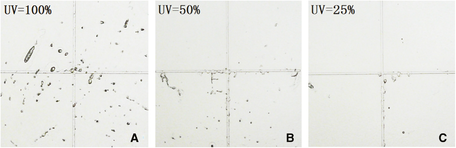
Effect of irradiation intensity on the number of bubbles: (A) the bubble holes around “cross” under 100%, (B) the bubble holes around “cross” under 50%, (C) the bubble holes around “cross” under 25%.
The average bubbles sum of the every group was 270, 160, and 60, which decreased with the decrease of irradiation intensity apparently. However, the bubbles of large diameter (d≥150 μm) still existed in the low irradiation intensity, as shown in Figure 8C. Irradiation intensity directly affects the cure rate. The low curing rate makes the curing duration long enough for feeding. Hence, the shrinkage and the resulting residue stress become smaller. The number of bubbles reduced as well. Although the bubble defect could be improved by reducing the irradiation intensity, the effect is limited. Moreover, lower irradiation intensity results in longer the molding cycle. The results showed that the cycle time was 70 s at irradiation intensity of 100%, 100 s at 50%, and much more time at 25%. Considering the forming efficiency, too low irradiation intensity is unacceptable in practical production.
4.1.3 The effect of material viscosity on the bubble defect
The experimental results (Figure 9C, F, I) showed that the bubbles decreased obviously with the dropping of material viscosity. The average diameter of bubbles reduced from 300 μm to 180 μm as well. As shown in Figure 9B, E, and H, it was demonstrated that the lower residue stress could be achieved at higher material viscosity. Higher viscosity mixture resin with higher adhesion results in lower curing rate and longer cycle time, which provide sufficient feeding capacity. Consequently, the stress concentration and vacuum bubbles decreased. However, the high viscosity material may influence the dimensional accuracy of micro structure. Therefore, the improvement method through adjusting the viscosity did not apply to production of microfluidic chips.

Experimental results of material viscosity on the number of shrinkage bubbles. (A, D and G) The number of bubbles in the product decreases with the decrease of the viscosity of the material. (B, E and H) The residual stress of the product varies with the increase of the viscosity of the material. (C, F and I) Local magnification of the picture A, D and G.
4.2 Effect of irradiation pattern on the bubble defect
Figure 10 showed the different products obtained by different irradiation patterns under the identity process conditions and formula. Compared with the part by stationary irradiation pattern as shown in Figure 10, the apparent bubble defects obtained by dynamic irradiation pattern were obviously eliminated.
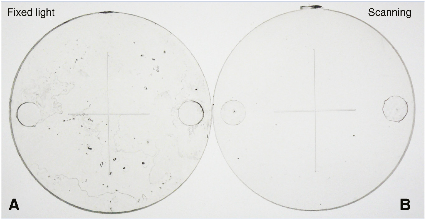
Products by scanning mode of light (B) and fixed light (A).
Figure 11 shows the micrograms on the equal position of the products gained via different irradiation patterns. The bubble defect becomes hardly invisible due to the dynamic irradiation pattern. With a laser microscope on both surfaces of roughness measurement, the blue line in Figure 11 was employed for line roughness sampling trajectory; the results showed that the rough degree Ra value was approximately 118 nm through the dynamic irradiation pattern, while Ra value was around 562 nm through stationary pattern. It further demonstrated that the apparent bubble defects were eliminated and greatly enhanced the appearance quality and transparency. It could be attributed to the difference of feeding process. The feeding direction is from the plane of mold core to the glass by stationary pattern, while it is along length direction from the gate to the internal core by dynamic pattern. It indicated that the feeding direction along the length is more suitable for method of UV-curing injection.

Surface structures under the microscope: (A) the surface of product obtained by fixing irradiation, (B) the surface of product obtained by scanning irradiation.
4.3 Preparation of microfluidic chips of cross flow channel
We have successfully fabricated microfluidic chips by employing UV-curing injection molding method. As shown in Figure 12, the microstructure basically meets the design requirements. As a contrary, we used the same mold core insert to fabricate microfluidic chips by traditional injection molding method with PMMA. The contour of the microstructure was compared with the one fabricated by UV-curing injection molding in Figure 13. It could be found that the dimensional accuracy of the product by UV-curing injection molding was higher than that by traditional injection molding. Considering the cost, efficiency, and molding precision, the method of UV light curing injection molding revealed remarkable advantages for manufacturing of microfluidic chip. Preliminary fluid mixing experiments were carried out successfully by applying the microfluidic chips we prepared in this paper (Figure 12B–C).

Microfluidic chips and test: (A) microfluidic chip successfully bond, (B) microfluidic chip has been used in fluid mixing experiments, (C) microscopic photo of the flow channel.

Micro channel profiles from laser scanning microscope.
5 Conclusion
We proposed a novel chemical method for microfluidic chips named UV light curing injection molding. The prototype and visualization experimental platform was set up successfully in this paper.
The dynamic process of bubble defect during UV light curing injection for microfluidic chip was observed and captured by using the visualization experimental platform. The bubble defect is mainly caused by too fast shrinkage rate, resulting in insufficient feeding capacity.
The experiment results indicated that rising of holding pressure, reducing the irradiation intensity, and increasing the viscosity of the formula could improve the bubble defects in certain extent. The dynamic irradiation pattern could obviously eliminate the bubble defect and produce good microfluidic chip for practical application.
The results proved that UV-curing injection molding method has much more advantages manufacturing of microfluidic chip in terms of the precision of micro channel. It is further proved that this method has a good prospect for the fabrication of microfluidic chips in the future.
Funding source: National Natural Science Foundation of China
Award Identifier / Grant number: 51573017
Award Identifier / Grant number: 21174015
Funding statement: The project is supported by the National Natural Science Foundation of China (grant nos. 51573017 and 21174015), Beijing Municipal Natural Science Foundation (no. 2162034), and the Fundamental Research Funds for the Central Universities (YS1403).
Acknowledgments
The project is supported by the National Natural Science Foundation of China (grant nos. 51573017 and 21174015), Beijing Municipal Natural Science Foundation (no. 2162034), and the Fundamental Research Funds for the Central Universities (YS1403).
References
[1] Manz A, Graber N, Widmer HM. Sens. Actuators B 1990, 1, 244–248.10.1016/0925-4005(90)80209-ISearch in Google Scholar
[2] Janasek D, Franzke1 J, Manz A. Nature 2006, 442, 374–380.10.1038/nature05059Search in Google Scholar PubMed
[3] Ren K, Zhou J, Wu H. Acc. Chem. Res. 2013, 46, 2396–2406.10.1021/ar300314sSearch in Google Scholar PubMed
[4] Cheng Y, Yang L, Guo C, Zhou Y, Yang Y. Adv. Mater. Res. 2012, 542–543, 891–894.10.4028/www.scientific.net/AMR.542-543.891Search in Google Scholar
[5] Chin CD, Linder V, Sia SK. Lab on A Chip. 2012, 12, 2118–2134.10.1039/c2lc21204hSearch in Google Scholar PubMed
[6] Volpatti LR, Yetisen AK. Trends Biotechnol. 2014, 32, 347–350.10.1016/j.tibtech.2014.04.010Search in Google Scholar PubMed
[7] Luo CW, Chiang YC, Cheng HC, Wu CZ, Huang CF, Wu CW, Shen YK, Lin Y. Polym. Eng. Sci. 2011, 51, 391–402.10.1002/pen.21840Search in Google Scholar
[8] Jiang BY, Liu Y, Chu CP, Qiu QJ. Adv. Mater. Res. 2009, 87–88, 381–386.10.4028/www.scientific.net/AMR.87-88.381Search in Google Scholar
[9] Liu Y, Song MC, Wang MJ, Zhang CZ. Mater. Sci. Forum. 2009, 628–629, 417–422.10.4028/www.scientific.net/MSF.628-629.417Search in Google Scholar
[10] Yu L, Koh CG, Lee LJ, Koelling KW, Madou MJ. Polym. Eng. Sci. 2002, 42, 871–888.10.1002/pen.10998Search in Google Scholar
[11] Lee BK. Polym. Eng. Sci. 2014, 54, 42–50.10.1002/pen.23535Search in Google Scholar
[12] Lucchetta G, Fiorotto M, Bariani PF. CIRP Ann. Manuf. Technol. 2012, 61, 539–542.10.1016/j.cirp.2012.03.091Search in Google Scholar
[13] Mcginniss VD, Kah A. Polym. Eng. Sci. 2004, 17, 478–483.10.1002/pen.760170711Search in Google Scholar
[14] Ikemura K, Tanaka H, Fujii T, Deguchi M, Negoro N, Endo T, Kadoma Y. Dent. Mater. J. 2011, 30, 493–500.10.4012/dmj.2011-012Search in Google Scholar PubMed
[15] Belyansky MP, Gloschenkov O, Poughkeepsie N. 2009, US20090155487.Search in Google Scholar
[16] Melchels FPW, Feijen J, Grijpma DW. Biomaterials. 2010, 31, 6121–6130.10.1016/j.biomaterials.2010.04.050Search in Google Scholar PubMed
[17] Xie P, Le S, Yuelin L, Yumei D, Weimin Y. J. Mech. Eng. 2015, 51, 90–95.10.3901/JME.2015.04.090Search in Google Scholar
©2017 Walter de Gruyter GmbH, Berlin/Boston
Articles in the same Issue
- Frontmatter
- Original articles
- Preparation of epoxy/acrylonitrile-butadiene-styrene copolymer/short carbon fiber composites with a self-made conical mixer
- Preparation and characterization of poly (amide-ester-imide)/Na+-MMT nanocomposite via ultrasonic method
- Polyurethane membrane with a cyclodextrin-modified carbon nanotube for pervaporation of phenol/water mixture
- Fabrication of chitosan/PEO nanofiber mats with mica by electrospinning
- Effect of cooling induced crystallization upon the properties of segmented thermoplastic polyurethanes
- Conductivity and dielectric analysis of nanocolloidal polypyrrole particles functionalized with higher weight percentage of poly(styrene sulfonate) using the dispersion polymerization method
- Mechanism and solutions of appearance defects on microfluidic chips manufactured by UV-curing assisted injection molding
- Effect of gas counter pressure on shrinkage and residual stress for injection molding process
- Ablation and mechanical investigation of heat vulcanizing silicone rubber (HVSR) composite containing carbon fibers
- Cavitation desulfurization in vulcanized rubber recycling under ultra-high pressure water jet