
Investigation of synthesis and processing of cellulose, cellulose acetate and poly(ethylene oxide) nanofibers incorporating anti-cancer/tumor drug cis-diammineplatinum (II) dichloride using electrospinning techniques
-
Saheem Absar
 ,
Kyle Edwards
,
Kyle Edwards

Abstract
A model anti-cancer/tumor drug cis-diammineplatinum (II) dichloride (cisplatin) was loaded into micro- and nanofibers of cellulose, cellulose acetate (CA) and poly(ethylene oxide) (PEO), using various electrospinning techniques. Single-nozzle electrospinning was used to fabricate neat fibers of each category. Drug loading in cellulose fibers was performed using single-nozzle electrospinning. Encapsulation of cisplatin in CA and PEO-based fibers was performed using coaxial electrospinning. Morphological analysis of the fibers was performed using scanning electron microscopy (SEM) and energy dispersive X-ray spectroscopy (EDS). The various categories of fibers exhibited diverse morphological features depending on the material compositions and applied process parameters. The drug-loaded cellulose nanofibers showed attached particles on the surface. These particles were composed of both the polymer and the drug. The CA-cisplatin fibers exhibited drug encapsulation within various diverse morphological conformations: hierarchical structures such as straw-sheaf-shaped particles, dendritic branched nanofibers and swollen fibers with large beads. However, in the case of PEO fibers, drug encapsulation was observed inside repeating dumbbell-shaped structures. Morphological development of the fibers and corresponding mode of drug encapsulation were correlated with process parameters such as applied voltage, concentrations and relative feed rates of the solutions and conductivities of the solvents.
1 Introduction
The electrospinning process is a facile method for production of micro- and nanoscale fibers from polymer materials. A charged polymer solution of sufficient viscosity suspended from a spinneret is drawn under the influence of high electrostatic forces towards a grounded collector. Charge repulsion among like charges can overcome the surface tension of the droplet above a critical voltage. This effect induces the elongation of the droplet into a characteristic Taylor cone, which subsequently leads to jetting of the solution into a conical envelope region of complex flow instabilities. The electrohydrodynamic jetting combined with the flow instabilities promote thinning of the jet along with solvent evaporation – which ultimately leads to the formation of solidified nanofibers on the collector [1–5].
The morphological characteristics of nanofibers can be tuned or modified by adjusting the electrospinning parameters. The wide array of adjustable parameters can be divided into three basic categories – solution, process and ambient parameters [6]. The solution parameters consist of the molecular weight of polymer [7, 8], concentration [9–12], viscosity [13, 14] surface tension [15] and conductivity [16]. The process parameters consist of voltage [17, 18], flow rate [19], collector type [20, 21] and distance between spinneret tip to collector [22, 23]. Ambient parameters such as humidity and temperature can also affect fiber morphology [24, 25]. Some of the parameters are interrelated to each other such as viscosity, polymer concentration and molecular weight. The solution viscosity and related chain entanglement effects can be adjusted by choosing a polymer of appropriate molecular weight or by adjusting the concentration [26, 27].
The prospect of incorporation or functionalization of bioactive agents such as drugs, proteins, enzymes, antibodies etc., with electrospun nanofibers make them versatile candidates for development of functional biomaterials such as drug delivery devices [28, 29], wound dressings [30] and tissue engineering scaffolds [31]. Attractive properties of nanofibers such as their extremely high specific surface area, ultra-high porosity and diverse morphological characteristics are relevant for such applications. For applications in development of drug delivery systems, the large surface area to volume ratio and high porosity of nanofiber membranes overcomes the limitation of high drug uptake associated with other types of drug delivery devices. Additionally, the release mechanism of drugs loaded within nanofibers can be adjusted by choosing a suitable polymer and also modifying morphological characteristics of the nanofibers such as the diameter, porosity and surface features. Such modifications can be achieved by adjusting the appropriate electrospinning process variables such as voltage, solution feed rate, ambient conditions, solution viscosity, surface tension and conductivity [32]. Drug loading into nanofibers can be accomplished by various methods such as coating, embedding, or encapsulation. Selection of a proper solvent system is also a critical step for ensuring stable electrospinning and consistent nanofiber production. Simple blending of both the drug and polymer dissolved in a mutually compatible solvent is one of the methods for preparing solutions for electrospinning. Electrospinning of drug loaded nanofibers was performed by Tungprapa and coworkers [28] from a solution of cellulose acetate (CA) in N,N-dimethylacetamide (DMAc) and acetone blended with various model drugs. Taepaiboon et al. [29] reported electrospinning of drug loaded poly(vinyl alcohol) nanofibers using various drugs blended with poly(vinyl alcohol) in distilled water. Ranganath and Wang [33] fabricated cancer drug paclitaxel loaded poly(D,L lactide-co-glycolide) (PLGA) nanofibers by electrospinning a blend solution of PLGA dissolved in dichloromethane (DCM) and N,N-dimethylformamide (DMF), and mixed with paclitaxel. Similar methods of electrospinning using solutions with a mutually compatible solvent for both the drug and polymer were also reported for fabrication of nanofibers of poly-ε-caprolactone (PCL)-polyphosphate containing nerve growth factor protein [34], PCL containing heparin [35] and PLLA loaded with tetracycline hydrochloride [36]. The drug and polymer can also be solubilized in separate solvent systems and mixed together. Kim and coworkers used a dual solution mixture of PLGA dissolved in DMF along with an aqueous solution of cefoxitin sodium dissolved in water to prepare cefoxitin loaded PLGA nanofibers [37]. Kenawy et al. [38] reported electrospinning of poly(ethylene-co-vinyl acetate) and poly(lactic acid) solutions in chloroform mixed with tetracycline HCl solution. Chen et al. [39] fabricated composite nanofibers of PLLA loaded with cisplatin, using dual solutions of PLLA in DCM and cisplatin in DMF. However, these methods of electrospinning using drugs blended with polymer solutions renders it difficult to ascertain complete encapsulation of the drug inside the nanofibers, since some of the drug particles may be partially embedded or exposed to the surface in the resultant nanofiber membrane or scaffold. Such approaches are more suited for applications where a quicker initial release of drugs from the nanofibers is desired. A drug release profile with low initial burst release is desirable for sustained and controlled delivery of drugs from a biodegradable polymer membrane. To overcome issues of drug encapsulation with conventional methods, nanofibers of a core-sheath morphology produced using coaxial electrospinning can be utilized. Separate solutions of drug and polymer can be loaded in separate concentric capillaries and coaxially electrospun to form nanofibers with a core-shell morphology. He and coworkers [40] produced drug-loaded core-shell nanofibers of PLLA using coaxial electrospinning. The sheath solution consisted of PLLA dissolved in chloroform and acetone. The core solution consisted of a model drug, tetracycline HCl dissolved in a mixture of methanol and chloroform with a small amount of PLLA. Huang et al. [41] fabricated two types of core-shell PCL nanofibers loaded with two model drugs by coaxial electrospinning. PCL dissolved in a mixture of chloroform and ethanol was used as the sheath solution. Two model drugs, resveratrol dissolved in ethanol and gentamycin sulfate in water, were used as core solutions. They observed that an increase in drug concentration resulted in a decrease in bead defects when drug and polymer solutions were miscible (resveratrol-loaded nanofibers). The opposite effect was observed when the drug and polymer solutions were immiscible (gentamycin sulfate loaded nanofibers) [41]. Jiang and coworkers [42] prepared biodegradable core-shell nanofibers by coaxial electrospinning of poly-DL-lactic acid (PDLLA) and poly(3-hydroxybutyrate) solutions. They reported the flow-rate of core liquid to have a predominant effect on both outer and inner fiber diameter. A core-shell structure can shift the release mechanism to drug diffusion and matrix degradation rather than desorption from the nanofiber surface [32, 43]. Optimum production of core-shell nanofibers can be achieved by adjusting parameters such as the relative feed rates, conductivity and viscosity of the core and shell solutions. Other factors such as the degree of dissimilarity, mutual interfacial interactions and rheological properties of the core and shell solutions are also important [42, 44]. A modified form of the coaxial electrospinning process for the preparation of ketoprofen loaded CA nanofibers was reported by Yu et al [45], where they investigated the effects of stabilizing the compound electrospinning jet with a non-spinnable sheath solvent. The core solution consisted of CA hybridized with a drug (ketoprofen). The sheath solution was a mixture of organic solvents. The core jet is subjected to electrical drawing for a longer period, facilitating homogeneous core jet solidification and retarding the formation of surface defects such as wrinkles on the surface of the nanofibers.
The focus of our work was to achieve encapsulation of a model drug (cisplatin) inside micro- or nanoscale fibers produced from various biocompatible polymers. The core solution used in our electrospinning experiments consisted of a drug (cisplatin) dissolved in a compatible organic solvent (DMF), which cannot be electrospun by itself to form fibers. We investigated the usage of a core drug solution without hybridizing it with a polymer or functionalization, to retain the physical state of the drug without further alteration. Coaxial electrospinning with a polymer-hybridized drug core and a sheath polymer would result in the formation of larger fibers.
One of the key processing issues in coaxial electrospinning is the proper selection of core and sheath solvents. However, specialized drugs or pharmaceutical agents for cancer treatment generally have a very limited range of compatible solvents. For instance, the anti-cancer drug cis-diammineplatinum(II) dichloride (cisplatin) is compatible with a limited number of solvents (DMF, DMA, DMSO). In some cases, a solvent compatible with the drug solution can be incompatible with the sheath solvent. As such, when both the solutions come in contact with each other at the coaxial spinneret tip, undesirable issues such as clogging of the spinneret tip due to precipitation of the polymer can be observed. Interfacial effects at the phase between the incompatible solutions can lead to unbalanced charge distributions on the compound solution droplet, resulting in the formation of nonuniform fibers with several structural defects, resulting in inefficient drug encapsulation. Therefore, regarding encapsulation of nonhybridized or non-functionalized drugs within a polymer matrix, these processing issues can substantially increase the complexity of coaxial electrospinning.
In this work, we have utilized the approaches of solution blending and coaxial electrospinning to prepare drug-loaded micro/nanofibers of three different biocompatible polymers: cellulose pulp, CA and poly(ethylene oxide) (PEO). Neat fibers of each polymer were fabricated using single-nozzle electrospinning. For loading of drugs in the fibers, the following experiments were performed:
Single-nozzle electrospinning of cellulose pulp dissolved in N-methylmorpholine N-oxide (NMMO.H2O), combined with a solution of cisplatin dissolved in DMF.
Coaxial electrospinning using sheath solutions of (i) CA and (ii) PEO. A solution of cisplatin in DMF was used as the core solution.
Due to various processing issues involving dissolution and compatibility with the drug solution, only single-nozzle mode was used for spinning of drug-loaded cellulose pulp fibers. Drug encapsulation was performed using coaxial spinning for CA and PEO solutions due to their stability at ambient conditions, easier processing steps and compatibility with the drug solution.
Comparative morphological analysis of neat and drug-loaded fibers of each material system was performed using scanning electron microscopy (SEM). Elemental analysis using energy dispersive X-ray spectroscopy (EDS) was used to verify the presence of cisplatin in the drug-loaded fibers. These observations provided insight into the mode of drug encapsulation in the fibers and assisted with the correlation of various process parameters with the morphological development of the various categories of nanofibers.
2 Materials and methods
The polymers used for fabricating the fibers consisted of cellulose pulp (DP 1230), CA (Mw 30,000 g/mol, acetyl content 39.8%) and PEO (Mw 100,000 g/mol). The solvents used were NMMO.H2O, acetone, DMAc, DMF and deionized water. The anti-cancer drug used was cis-diammineplatinum (II) dichloride or cisplatin. Other additives consisted of sodium chloride (NaCl) salt and propyl gallate, an antioxidant. The polymers, solvents and the drug were procured from Sigma Aldrich (St. Louis, MO, USA). Cellulose pulp was acquired from Georgia-Pacific (GP) cellulose (Atlanta, GA, USA). Cisplatin was dissolved in DMF at a concentration of 5 mg/ml. DMF was used as the drug solution. DMF was chosen as the solvent due to its compatibility with cisplatin.
The experiments were performed using a MECC NF-500 electrospinning unit. The unit consists of dual syringe feed pumps, customizable spinneret attachments and a high voltage power supply. Neat nanofibers of each category were prepared by single-nozzle electrospinning (Figure 1A). The drug-loaded fibers were prepared by coaxial electrospinning (Figure 1B). The specialized coaxial spinneret (Figure 2) consisted of a 0.6 mm sheath nozzle and a 27-gauge core nozzle placed concentrically inside the sheath nozzle. The tip of the core nozzle was extended 0.5 mm below the tip of the sheath nozzle. The polymer and drug solutions were fed through the sheath and core nozzles, respectively, using Teflon tubes connected to individual syringe pumps. The positive terminal of a high voltage power source was connected to the body of the spinneret. The ground terminal of the power source was connected to a steel plate collector placed below the spinneret. The steel plate was covered with an aluminum foil which was used as the fiber deposition substrate. The process parameters, voltage, spinneret tip-to-collector distance and feed rates, were adjusted by using the control unit of the NF-500 system.
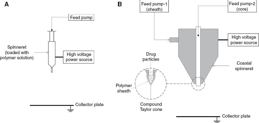
Electrospinning configurations: (A) single-nozzle, (B) coaxial.
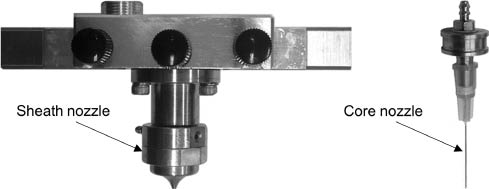
Coaxial spinneret.
Morphological analysis of both the neat and drug-loaded fibers was performed using a JEOL JSM-7600F scanning electron microscope (JEOL USA, Peabody, MA, USA). Elemental analysis for determining the fiber compositions was performed using EDS. One centimeter squares of fiber samples of each category were cut from the aluminum foil substrate and sputter-coated with a layer of gold for observation in the SEM. Measurements of dimensions of fibers and particles were performed using the “ImageJ” (NIH, Bethesda, MD, USA) application.
3 Results and discussion
The solution compositions for each type of polymer and the drug used for the electrospinning experiments are shown in Table 1. The relevant electrospinning process parameters for each category are shown in Table 2.
Solution compositions used for electrospinning.
| Solution | Material | Solvent | Concentration |
|---|---|---|---|
| A | Cisplatin | DMF | 5 mg/ml |
| B | Cellulose pulp | NMMO.H2O | 2 wt% |
| C | Cellulose acetate | Acetone+DMAc (2:1 v/v) | 2 wt% |
| D | PEO | Deionized water+0.9 wt% NaCl | 20 wt% |
DMAc, dimethylacetamide; DMF, dimethylformamide; NMMO, N-methylmorpholine N-oxide; PEO, poly(ethylene oxide).
Electrospinning parameters.
| Materials | Solution | Feed rate (ml/h) | Voltage (kV) | Collector distance (mm) | Relative humidity (%) | Sample morphology |
|---|---|---|---|---|---|---|
| Cellulose (neat) | B | 0.03–0.1 | 22 | 100 | 60 | Interconnected nanofibers |
| Cellulose+cisplatin | B+A | 0.05–0.1 | 28 | 100 | 60 | Particles attached to fiber surface |
| CA (neat) | C | 0.5–1.0 | 25 | 150 | 35 | Regular nanofibers |
| CA+cisplatin | Sheath: C Core: A | 0.5 (s); 0.2 (c) | 15 | 150 | 35 | Electrosprayed particles |
| 0.3 (s) 0.2 (c) | 25 | 210 | 35 | Highly branched fibers | ||
| 0.5 (s) 0.2 (c) | 17–20 | 210 | 35 | Fibers with beads | ||
| PEO (neat) | D | 0.5 | 24 | 120 | 50 | Regular nanofibers |
| PEO+cisplatin | Sheath: D Core: A | 1.0 (s) 0.2–0.6 (c) | 22 | 125 | 44 | Nanofibers with repeating beads |
c, core; s, sheath; CA, cellulose acetate.
A solution of cellulose pulp was prepared using NMMO as the solvent. NMMO powder was first dissolved in 10 ml of deionized water. Powdered cellulose pulp was then added to this solution at a loading of 2 wt%. Antioxidant propyl gallate was added at 1 wt% of cellulose, to prevent degradation of the cellulose solution during mixing. The solution was heated at 40–50°C in a sealed flask connected to a vacuum aspirator. Heating in a vacuum environment enabled the usage of a lower solution heating temperature to boil the water content. The reduction of water content is known to enhance the dissolution of cellulose pulp in NMMO [46]. A 27-gauge needle was used as the nozzle for the spinneret. The blend solution of cellulose and cisplatin was not heated while spinning, due to the instability of cisplatin solutions at elevated temperatures, where it undergoes a cis-trans isomerization. As such, we avoided heating the spinneret during single-nozzle spinning to avoid changing the physical properties of the drug.
Due to complications in effective dissolution of cellulose pulp in NMMO, the resulting solution had a paste-like viscosity even at low loading levels (2 wt%) of cellulose pulp. As such, single-nozzle electrospinning was used for both the cellulose pulp solutions with and without drug for easier processing. However, the resulting yield of nanofibers was too low due to high instability in the electrospinning jet, which mostly led to electrospraying of the solution. The nanofiber samples were washed with deionized water to extract any remaining NMMO solvent and to precipitate the cellulose fibers. The spinning parameters are listed in Table 2.
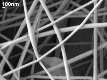
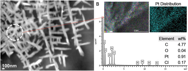
SEM images of neat cellulose nanofibers showed an interconnected web of nanofibers of 70–90 nm, as shown in Figure 3. However, the nanofibers were discontinuous and showed many surface defects. Electrospinning of the cellulose-cisplatin solution yielded a very low volume of production of fibers. SEM images of fibers of this category did not exhibit any encapsulation of the cisplatin particles within the fibers. Aggregated particles of cellulose and cisplatin were observed on the surface of the fibers, as shown in Figure 4A. EDS analysis was performed to determine the presence of cisplatin in the fibers by observing peaks of platinum (Pt) and chlorine (Cl) in the spectrum, as shown in Figure 4B. The weight percentage of characteristic elements of cellulose (C, O) and cisplatin (Pt, Cl) are also shown in Figure 4B, and it can be observed that the cisplatin content compared to cellulose is too low. This can be attributed to the EDS spectrum being based on a single point scan.
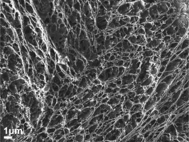
Scanning electron microscopy (SEM) image of neat cellulose nanofibers.
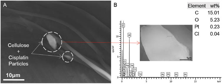
(A) Formation of aggregates of cellulose and cisplatin particles on the fibers, (B) corresponding energy dispersive X-ray spectroscopy (EDS) spectrum (scanning area shown in inset).
Cellulose has poor solubility in conventional solvents and results in high viscosity of spinning dopes, due to its strong intermolecular hydrogen bonding network. Derivatives of cellulose such as CA are easier to process, and are readily soluble in conventional solvents. The rate of evaporation of the polymer solvent during spinning can be optimized by mixing a higher volatility solvent (such as acetone) with a solvent of lower volatility (such as DMAc, acetic acid, DMF, water). The solvent characteristics and CA concentration also affect the resultant fiber morphology [47].
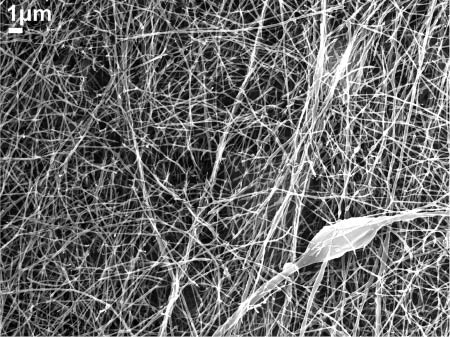
A solvent system of acetone and DMAc at a ratio of 2:1 (v/v) was used for preparing the CA solutions. DMAc was added to increase the conductivity of the solution to be used for electrospinning. CA powder was slowly dissolved in the solvent mixture at a concentration of 7.5 wt% under vigorous stirring with a homogenizer. Electrospinning of CA solutions yielded a higher volume of nanofibers compared to the cellulose pulp solutions. The resulting neat CA nanofibers were uniform and randomly distributed with minimal defects, with a size distribution between 70 nm and 150 nm, as shown in Figure 5.
Scanning electron microscopy (SEM) image of neat cellulose acetate nanofibers.
The coaxial electrospinning experiments for encapsulation of cisplatin in a CA-based sheath yielded three populations of samples with distinctive morphological features. The morphological development was affected by the electrospinning process parameters. The initial parameters consisted of a voltage of 15 kV, a sheath solution (CA) feed rate of 0.5 ml/h and a core solution (cisplatin) feed rate of 0.2 ml/h. The tip-to-collector distance was maintained at 150 mm. A stable Taylor cone could not be obtained at these parameters, which subsequently resulted in electrospraying of the solution droplet. These effects resulted in the formation of crystalline straw-sheaf microstructures of CA conjugated with cisplatin, as shown in Figure 6. The size distribution of the microstructures varied widely with sizes as small as 2–10 μm, and larger structures of 30–60 μm in length. A magnified SEM image of the straw-sheaf-like structure is shown in Figure 7A. The hierarchical microstructure is composed of a bundle of thin filaments clustered together with a narrow contraction in the middle. EDS analysis indicated the cisplatin content in the structure through the presence of Pt and Cl peaks in the EDS spectrum, as shown in Figure 7B. The cisplatin particles were uniformly distributed on the structure, as shown by the EDS map of the Pt distribution given in the inset of Figure 7B.
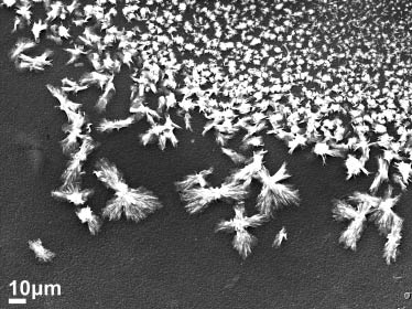
Scanning electron microscopy (SEM) image of electrosprayed cellulose acetate (CA)-cisplatin particles.
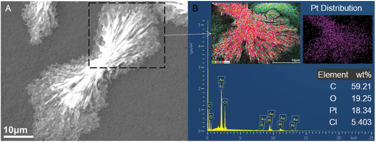
(A) Magnified scanning electron microscopy (SEM) image of the cellulose acetate (CA)-cisplatin straw-sheaf microstructure, (B) corresponding energy dispersive X-ray spectroscopy (EDS) spectrum (scanning area and Pt distribution map shown in inset).
The process parameters were subsequently adjusted to a higher voltage of 25 kV, while maintaining the solution feed rates of the sheath (CA) at 0.3 ml/h and core (cisplatin) at 0.2 ml/h. The tip-to-collector distance was kept at 210 mm. The compound Taylor cone exhibited a different mode of behavior upon application of a higher voltage. Extensive jet splaying and whipping instabilities were observed at the compound solution droplet. This set of parameters generated continuous nanofibers with repeating dendritic branched features aligned uniformly on the deposition area, as shown in Figure 8. Each of the hierarchical structures are composed of periodically spaced branches of varying sizes of 7–20 μm in length, protruding from a long continuous main stem of 0.7–1 μm in diameter. The sub-branches are further subdivided into more branches follwing a pattern similar to the aforementioned configuration. The main stems are arranged unidirectionally in parallel and are spaced apart at distances varying from 17 μm to 25 μm. A magnified SEM image of the branching pattern is shown in Figure 9A. The hierarchical structure is evident even at the nanoscale. The stems diameters vary from 75 nm to 100 nm, with protruding branches as small as 130–150 nm and larger branches of 300–700 nm in length. The diameters of the branches vary between 60 nm and 90 nm. EDS scan of an area of the branched structure indicated the presence of cisplatin, as shown in Figure 9B.
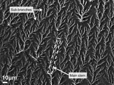
Scanning electron microscopy (SEM) image of hierarchically branched microfibers of cellulose acetate (CA) loaded with cisplatin.
(A) Magnified scanning electron microscopy (SEM) image of sub-branches of cellulose acetate (CA)-cisplatin fibers, (B) corresponding energy dispersive X-ray spectroscopy (EDS) spectrum (scanning area and Pt distribution map shown in inset).
The formation of these highly branched hierarchical structures indicates the occurrence of branching effects both during drawing of the electrospinning jet and solidification of the fibers on the collector. The combined effect of extremely high electrical stresses and surface tension can generate complex static undulations on the surface of a conducting fluid jet. Such undulating sites on the jet surface can influence the formation of flow instabilities leading to the emanation of lateral branches from the primary jet [48]. As shown by Holzmeister et al. [49], formation of reguarly spaced barbs on nanofibers can be generated due to the competition between slow charge relaxation and the electrically driven surface instabilities on the electrospinning jet. When the disparity of the slow charge relaxation compared to the rate of growth of the secondary instabilities becomes more pronounced, the barbs can transform to full scale long branches. Factors leading to such disparities are influenced by the polymer solution conductivity and viscoelasticity. Addition of solvents with high dielectric constants such as DMF and DMAc into spinning solutions can induce extensive jet splaying during electrospinning. Hsu and Shivkumar [50] observed that addition of DMF in solutions of PCL in DCM caused initiation of jet splaying into multiple mini-jets almost immediately below the spinneret or needle tip. The jet-splitting effects also affected the resultant fiber morphology, by generating multimodal size distributions in the produced fibers.
The fractal-like nature of the branching exhibited in Figure 9A also suggests the ocurrence of a dielectric breakdown in the fibers during solidification of the electrospinning jet on the collector plate. These conductive paths resemble tree-like branched or dendritic features, also known as Lichtenberg figures [51]. The formation of the self-similar or fractal-like nature of the resultant structure can be explained by the process of “diffusion-limited aggregation” [52]. In this process, particles undergoing diffusion in a medium aggregate around seed particles which act as nucleation centers. The repetitive process results in a highly branched cluster of particles, since the arriving particles are more likely to be attached to the tips of outer branches than maneuver towards the inner regions. New branches are also generated from each tip site, which result in the formation of a self-similar branched fractal stucture. Dawar and Chandra [53, 54] showed the effect of an external electric field in diffusion-limited aggregation-influenced branched fractal formation in conductive polymer electrolytes dispersed with Al2O3 seed particles. The electric field allows the formation of ordered branched structures aligned along the electric field direction. Branched structure growth in this case is governed by a complex interplay of diffusion, migration and electroconvection.
In our experiment, when subjected to a substantially higher voltage of 25 kV, higher drawing forces on the compound droplet ejected from the spinneret introduced a larger volume of the core cisplatin solution with the electrospinning jet. Upon contact with the grounded collector, a rapid discharge of excess charges in the compound solution jet was initiated due to dielectric breakdown, resulting in the creation of electrically conductive paths along the surface of the fibers. Seed particles of cisplatin in the solution acted as nucleation centers for aggregation of more cisplatin particles as branched clusters. The EDS scanning map of the branched fibers shown in Figure 9B shows the elemental distribution of Pt, which supports the model of branched cluster formation of cisplatin particles. Finally, evaporation of the solvent yielded an ordered arrangement of highly branched CA fibers on the collector.
Further adjustment of the parameters generated a third population of fibers containing large beads, as shown in Figure 10. The voltage was varied between 17 kV and 20 kV and the sheath and core solution feed rates were maintained at 0.5 ml/h and 0.2 ml/h, respectively. The fibers ranged in size from 500 nm to 1 μm, with larger fibers between 2 μm and 6 μm. The larger fibers seem to be fused and interconnected with several adjacent fibers along their length.
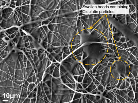
Swollen beads on cellulose acetate fibers loaded with cisplatin.
A large bead present in the observed sample was perforated by increasing the SEM acceleration voltage and focusing the high intensity electron beam of the SEM at a single point on it. The subsequent degradation of the CA sheath of the bead exposed an inner layer of cisplatin particles dispersed within the interior of the solid bead, as shown in Figure 11A. An EDS scan of the bead site was performed which indicated encapsulation of the cisplatin particles within a layer of CA, shown in Figure 11B.
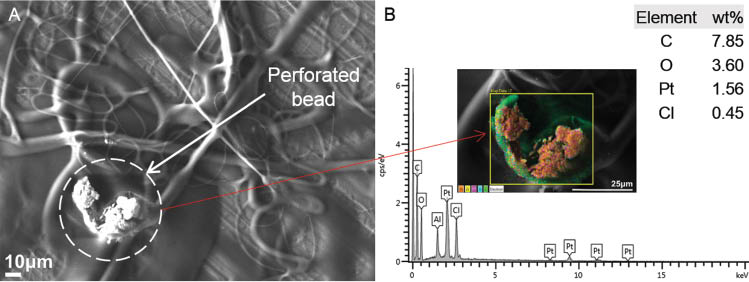
(A) Cisplatin particles dispersed inside a perforated bead of cellulose acetate (CA), (B) corresponding energy dispersive X-ray spectroscopy (EDS) spectrum (scanning area shown in inset).
To summarize our observations regarding the morphological evolution of structures from the coaxial electrospinning of CA and cisplatin solutions, the parameters (applied voltage, sheath flow rate, tip-to-collector distance) were adjusted to enable the proper formation of fibers from the electrospinning jet, while also achieving suitable encapsulation of the drug solution inside the sheath solution. The initial set of parameters (15 kV, 25 kV) provided us the indication of the behavior of the compound solution during coaxial spinning at the lower and upper bounds, and their effects on sample fiber morphology. For example, at 15 kV the compound solution led to electrospraying, which formed drug-loaded microparticles. At 25 kV, the solution formed highly branched drug-loaded fibers. These observations indicate that at lower voltages, viscoelastic effects overcome the electrical stresses, while at extremely high voltages the electrical stresses play a much more dominant role in determining the fiber morphology. The population of fibers observed in Figure 10 was formed at a moderate voltage range of 17–20 kV. At this set of parameters, the spinning jet was more stable and continuous, leading to the formation of randomly distributed beaded drug-loaded fibers.
For electrospinning experiments of PEO nanofibers, a 20 wt% PEO solution in deionized water was prepared under constant stirring with a magnetic stirrer. NaCl (0.9 wt%) was added to the deionized water to increase the solution conductivity. Neat PEO nanofibers were produced using single-nozzle electrospinning (parameters listed in Table 2). The resultant nanofibers were randomly distributed and showed uniform surface features. An SEM image of the neat PEO nanofibers is shown in Figure 12. The diameters of the nanofibers were widely distributed between 80 nm and 200 nm.
Scanning electron microscopy (SEM) image of neat poly(ethylene oxide) (PEO) nanofibers.
Coaxial electrospinning was subsequently performed to encapsulate cisplatin inside PEO nanofibers. The feed rate of the sheath was maintained at 1.0 ml/h, and the core solution feed rate was varied between 0.2 ml/h and 0.6 ml/h. Other process paramaters (voltage, collector distance, relative humidity) are listed in Table 2. The drug-loaded PEO nanofibers displayed the formation of sporadically spaced beaded structures along the length of the fibers, as shown in Figure 13. The dumbbell-shaped features suggest the encapsulation of drug particles inside the PEO shell layer. The beads vary between 140 nm and 170 nm and the connecting fibers vary between 45 nm and 70 nm in size. The magnified SEM image of Figure 14 shows clear phase separation between the core and sheath layers. The sheath layer thickness ranged between 8 nm and 25 nm, while the core layer thickness ranged between 43 nm and 108 nm in the beads, and 30 nm and 40 nm in the connecting nanofibers between the beads.
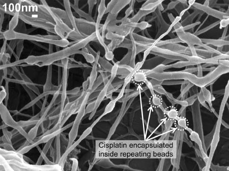
Drug-loaded poly(ethylene oxide) (PEO) nanofibers showing formation of repeating beads containing cisplatin.
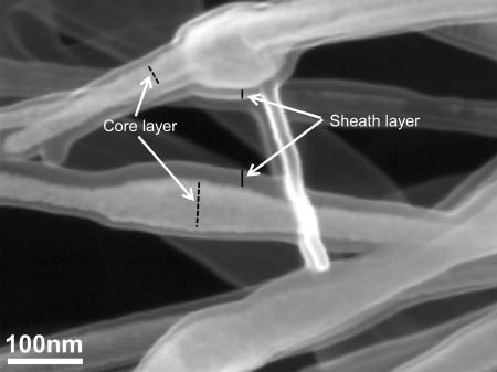
Magnified scanning electron microscopy (SEM) image of cisplatin-loaded poly(ethylene oxide) (PEO) nanofibers showing formation of distinct core and sheath layers.
Core-sheath fiber formation is affected by the difference in conductivity between the sheath and core solutions. The core solution contains DMF, which is a polyelectrolytic solvent with higher conductivity than the sheath solution containing water. Compared to the sheath solution, the core solution experiences higher charge buildup, leading to increased extensional forces in the core solution due to surface charge repulsion. Additionally, the viscosity and surface tension of the core solution are much lower than that of the shell solution, which render it incapable of forming fibers. A lower viscosity core solution will thus initiate jet breakup during electrospinning [55]. For fiber formation with continuous core-shell structure using coaxial electrospinning, the core solution should be confined within the sheath through the effect of viscous drag. If the core solution is significantly lower in viscosity than the sheath, jet breakup of the core solution will occur. This effect will cause the core solution to be pulled intermittently inside the sheath. The sheath will then spread along its length and migrate towards the droplet to hold it inside a beaded structure. A schematic of this process is shown in Figure 15. As such, the reduction of size of the connecting nanofibers (15–20 nm) between the droplets compared to the neat PEO fibers (40–160 nm) can be attributed to the effects of droplet migration. Díaz et al. [56] described encapsulation of hydrophobic liquids in hydrophilic polymer nanofibers using coaxial electrospinning. They obtained nanofibers which encapsulated oil within periodically spaced beads. The inner oil did not form a continuous core, but a string of discrete pockets. The inner jet (oil) of the compound Taylor cone being a Newtonian liquid, underwent varicose break-up at a faster rate than the solidification of the outer sheath, even though the small interfacial tension and the high viscosity of the outer liquid slowed down the break-up process. They found that the bead-to-bead distance and fiber diameter may be controlled by the outer liquid flow rate, while the bead diameter may be controlled by adjusting the inner liquid flow rate.
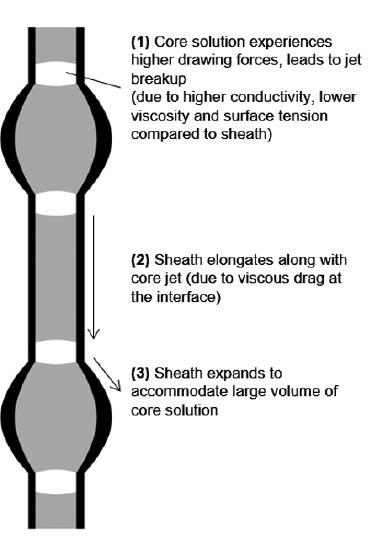
Formation of beaded structures due to jet breakup effects in core solution during coaxial electrospinning.
4 Conclusion
Micro- and nanoscale fibers of cellulose, CA and PEO were fabricated using electrospinning. A model anti-cancer/tumor drug, cis-diammineplatinum (II) dichloride (cisplatin) was encapsulated in the fibers using coaxial electrospinning. Morphological analysis of the various categories of fibers was performed using SEM and EDS. The fibers exhibited diverse morphological features depending on the material compositions and process parameters. Drug-loaded cellulose nanofibers showed particles composed of both cellulose and cisplatin attached to the surface. The CA-cisplatin fibers exhibited drug encapsulation within various diverse morphological configurations composed of swollen fibers and hierarchical structures of straw-sheaf like microparticles and branched fibers. Nanofibers of PEO showed encapsulation of drug inside repeating dumbbell-shaped structures formed along the length of the nanofibers. The morphological characteristics and manner of drug encapsulation were correlated with process parameters such as applied voltage, concentrations and relative feed rates of the solutions and conductivities of the solvents.
Acknowledgments
The authors would like to acknowledge support from the National Science Foundation (NSF) for this work through Grant #DMR-1337545. We also acknowledge the support from the FRC grant and RA investment grant provided by Georgia Southern University. We would also like to thank Dr. Hao Chen for his assistance in SEM and EDS characterization studies.
References
[1] Theron S, Zussman E, Yarin A. Polymer 2004, 45, 2017–2030.10.1016/j.polymer.2004.01.024Search in Google Scholar
[2] Huang Z, Zhang Y, Kotaki M, Ramakrishna S. Compos. Sci. Technol. 2003, 63, 445–466.10.1016/S0266-3538(02)00220-8Search in Google Scholar
[3] Ramakrishna S, Fujihara K, Teo W, Yong T, Ma Z, Ramaseshan R. Mater. Today 2006, 9, 40–50.10.1016/S1369-7021(06)71389-XSearch in Google Scholar
[4] Teo W, Ramakrishna S. Nanotechnology 2006, 17, R89.10.1088/0957-4484/17/14/R01Search in Google Scholar
[5] Shin Y, Hohman M, Brenner M, Rutledge G. Appl. Phys. Lett. 2001, 78, 1149.10.1063/1.1345798Search in Google Scholar
[6] Li Z, Wang C. One-Dimensional Nanostructures, Springer: Berlin, 2013, p. 15.10.1007/978-3-642-36427-3_2Search in Google Scholar
[7] Zhang J, Liu H, Xu H, Ding J, Zhuang X, Chen X, Chang F, Xu J, Li Z. RSC Adv. 2014, 4, 41696–41704.10.1039/C4RA07216BSearch in Google Scholar
[8] Koski A, Yim K, Shivkumar S. Mater. Lett. 2004, 58, 493–497.10.1016/S0167-577X(03)00532-9Search in Google Scholar
[9] Deitzel J, Kleinmeyer J, Harris D, Tan NB. Polymer 2001, 42, 261–272.10.1016/S0032-3861(00)00250-0Search in Google Scholar
[10] Eda G, Shivkumar S. J. Appl. Polym. Sci. 2007, 106, 475–487.10.1002/app.25907Search in Google Scholar
[11] Fong H, Chun I, Reneker D. Polymer 1999, 40, 4585–4592.10.1016/S0032-3861(99)00068-3Search in Google Scholar
[12] Lee K, Kim H, Bang H, Jung Y, Lee S. Polymer 2003, 44, 4029–4034.10.1016/S0032-3861(03)00345-8Search in Google Scholar
[13] Tiwari S, Venkatraman S. Mater. Sci. Eng. C 2012, 32, 1037–1042.10.1016/j.msec.2012.02.019Search in Google Scholar
[14] Rošic R, Pelipenko J, Kocbek P, Baumgartner S, Bešter-Rogač M, Kristl J. Eur. Polym. J. 2012, 48, 1374–1384.10.1016/j.eurpolymj.2012.05.001Search in Google Scholar
[15] Yang Q, Li Z, Hong Y, Zhao Y, Qiu S, Wang C, Wei Y. J. Polym. Sci. Pol. Phys. 2004, 42, 3721–3726.10.1002/polb.20222Search in Google Scholar
[16] Angammana C, Jayaram S. IEEE T. Ind. Appl. 2011, 47, 1109–1117.10.1109/TIA.2011.2127431Search in Google Scholar
[17] Zhang C, Yuan X, Wu L, Han Y, Sheng J. Eur. Polym. J. 2005, 41, 423–432.10.1016/j.eurpolymj.2004.10.027Search in Google Scholar
[18] Yuan X, ZhangY, Dong C, Sheng J. Polym. Int. 2004, 53, 1704–1710.10.1002/pi.1538Search in Google Scholar
[19] Zargham S, Bazgir S, Tavakoli A, Rashidi AS, Damerchely R. J. Eng. Fiber. Fabr. 2012, 7, 42–49.10.1177/155892501200700414Search in Google Scholar
[20] Xua CY, Inaic R, Kotakib M, Ramakrishna S. Biomaterials 2004, 25, 877–886.10.1016/S0142-9612(03)00593-3Search in Google Scholar
[21] Neves N, Campos R, Pedro A, Cunha J, Macedo F, Reis R. Int. J. Nanomed. 2007, 2, 433–438.Search in Google Scholar
[22] Mazoochi T, Hamadanian M, Ahmadi M, Jabbari V. Int. J. Ind. Chem. 2012, 3, 2.10.1186/2228-5547-3-2Search in Google Scholar
[23] Cha DI, Kim KW, Chu GH, Kim HY, Lee KH, Bhattarai N. Macromol. Res. 2006, 14, 331–337.10.1007/BF03219090Search in Google Scholar
[24] Mit-uppatham C, Nithitanakul M, Supaphol P. Macromol. Chem. Phys. 2004, 205, 2327–2338.10.1002/macp.200400225Search in Google Scholar
[25] Casper C, Stephens J, Tassi N, Chase D, Rabolt J. Macromolecules 2004, 37, 573–578.10.1021/ma0351975Search in Google Scholar
[26] Shenoy S, Bates W, Frisch H, Wnek G. Polymer 2005, 46, 3372–3384.10.1016/j.polymer.2005.03.011Search in Google Scholar
[27] Ferry J. Viscoelastic Properties of Polymers, Wiley: New York, 1980.10.1016/B978-0-08-022039-0.50009-6Search in Google Scholar
[28] Tungprapa S, Jangchud I, Supaphol P. Polymer 2007, 48, 5030–5041.10.1016/j.polymer.2007.06.061Search in Google Scholar
[29] Taepaiboon P, Rungsardthong U, Supaphol P. Nanotechnology 2006, 17, 2317.10.1088/0957-4484/17/9/041Search in Google Scholar
[30] Unnithan AR, Barakat NAM, Pichiah PBT, Gnanasekaran G, Nirmala R, Cha Y, Jung C, El-Newehy M, Kim HY. Carbohydr. Polym. 2012, 90, 1786–1793.10.1016/j.carbpol.2012.07.071Search in Google Scholar
[31] Yoshimoto H, Shin YM, Terai H, Vacanti JP. Biomaterials 2003, 24, 2077–2082.10.1016/S0142-9612(02)00635-XSearch in Google Scholar
[32] Pillay V, Dott C, Choonara YE, Tyagi C, Tomar L, Kumar P, du Toit LC, Ndesendo VMK. J. Nanomater. 2013, 789289. doi: 10.1155/2013/789289, Article ID: 789289.10.1155/2013/789289Search in Google Scholar
[33] Ranganath SH, Wang C. Biomaterials 2008, 29, 2996–3003.10.1016/j.biomaterials.2008.04.002Search in Google Scholar PubMed
[34] Chew SY, Wen J, Yim EKF, Leong KW. Biomacromolecules 2005, 6, 2017–2024.10.1021/bm0501149Search in Google Scholar PubMed
[35] Luong-Van E, Grøndahl L, Chua KN, Leong KW, Nurcombe V, Cool SM. Biomaterials 2006, 27, 2042–2050.10.1016/j.biomaterials.2005.10.028Search in Google Scholar PubMed
[36] He C, Huang Z, Han X. J. Biomed. Mater. Res. A 2009, 89A, 80–95.10.1002/jbm.a.32004Search in Google Scholar PubMed
[37] Kim TG, Lee DS, Park TG. Int. J. Pharm. 2007, 338, 276–283.10.1016/j.ijpharm.2007.01.040Search in Google Scholar
[38] Kenawy E, Abdel-Hay FI, El-Newehy MH, Wnek GE. Mat. Sci. Eng. A-Struct. 2007, 459, 390–396.10.1016/j.msea.2007.01.039Search in Google Scholar
[39] Chen P, Wu Q, Ding Y, Zhu Z. NANO 2011, 06, 325.10.1142/S1793292011002688Search in Google Scholar
[40] He C, Huang Z, Han X, Liu L, Zhang H, Chen L. J. Macromol. Sci.B 2006, 45, 515–524.10.1080/00222340600769832Search in Google Scholar
[41] Huang Z, He C, Yang A, Zhang Y, Han X, Yin J, Wu Q. J. Biomed. Mater. Res. A 2006, 77A, 169–179.10.1002/jbm.a.30564Search in Google Scholar PubMed
[42] Jiang H, Wang L, Zhu K. J. Control. Release 2014, 193, 296–303.10.1016/j.jconrel.2014.04.025Search in Google Scholar PubMed
[43] Sill TJ, von Recum HA. Biomaterials 2008, 29, 1989–2006.10.1016/j.biomaterials.2008.01.011Search in Google Scholar PubMed
[44] Moghe AK, Gupta BS. Polym. Rev. 2008, 48, 353–377.10.1080/15583720802022257Search in Google Scholar
[45] Yu D, Yu J, Chen L, Williams G, Wang X. Carbohydr. Polym. 2012, 90, 1016–1023.10.1016/j.carbpol.2012.06.036Search in Google Scholar
[46] Rosenau T, Potthast A, Sixta H, Kosma P. Prog. Polym. Sci. 2001, 26, 1763–1837.10.1016/S0079-6700(01)00023-5Search in Google Scholar
[47] Tungprapa S, Puangparn T, Weerasombut M, Jangchud I, Fakum P, Semongkhol S, Meechaisue C, Supaphol P. Cellulose 2007, 14, 563–575.10.1007/s10570-007-9113-4Search in Google Scholar
[48] Yarin A, Kataphinan W, Reneker D. J. Appl. Phys. 2005, 98, 064501.10.1063/1.2060928Search in Google Scholar
[49] Holzmeister A, Yarin A, Wendorff J. Polymer 2010, 51, 2769–2778.10.1016/j.polymer.2010.04.005Search in Google Scholar
[50] Hsu C, Shivkumar S. Macromol. Mater. Eng. 2004, 289, 334–340.10.1002/mame.200300224Search in Google Scholar
[51] Niemeyer L, Pietronero L, Wiesmann HJ. Phys. Rev. Lett. 1984, 52, 1033–1036.10.1103/PhysRevLett.52.1033Search in Google Scholar
[52] Amir S, Mohamed NS, Ali SAH. Aspects on Fundaments and Applications of Conducting Polymers, Intech, Rijeka, Croatia, 2012, p. 194.Search in Google Scholar
[53] Dawar A, Chandra A. Phys. Lett. A 2014, 378, 2951–2958.10.1016/j.physleta.2014.08.016Search in Google Scholar
[54] Dawar A, Chandra A. Phys. Lett. A 2012, 376, 3604–3608.10.1016/j.physleta.2012.10.034Search in Google Scholar
[55] Li D, Xia Y. Nano Lett. 2004, 4, 933–938.10.1021/nl049590fSearch in Google Scholar
[56] Díaz J, Barrero A, Márquez M, Loscertales I. Adv. Func. Mater. 2006, 16, 2110–2116.10.1002/adfm.200600204Search in Google Scholar
©2015 by De Gruyter
Articles in the same Issue
- Frontmatter
- Original articles
- Visualization and simulation of filling process of simultaneous co-injection molding based on level set method
- Effect of compatibilizer on the properties of PBS/lignin composites prepared via a vane extruder
- Fabrication and characterization of thermally conductive composites based on poly(butylene terephthalate)/glass fiber-silicon carbide
- Preparation and characterization of poly(MMA-EGDMA-AMPS) microspheres by soap-free emulsion polymerization
- Modification of biaxially oriented polypropylene films using dicyclopentadiene based hydrogenated hydrocarbon resin
- Investigation of synthesis and processing of cellulose, cellulose acetate and poly(ethylene oxide) nanofibers incorporating anti-cancer/tumor drug cis-diammineplatinum (II) dichloride using electrospinning techniques
- Grafting poly(2-acryloyloxyethyl trimethyl ammonium chloride) branches onto the backbones of corn starch for toughening starch film
- Erosion characteristics of Teflon under different operating conditions
- Development of sustainable resource based poly(urethane-etheramide)/Fe2O3 nanocomposite as anticorrosive coating materials