Performance and field implementation of a new fracturing fluid consisting of hydrophobically associating polyacrylamide and anionic surfactant
-
Zhongcong Zhao
 ,
Tongyi Liu
,
Tongyi Liu

Abstract
The fundamental cause of the proppant suspension behavior in hydraulic fracturing fluids lies in its internal microcosmic network structure and structural strength. In addition to chemical crosslinking, another method to form a network structure is established in this paper. Hydrophobically associating polyacrylamide and an anionic surfactant self-assembly process was applied to form a network structure. Compared with crosslinked hydroxypropyl guar gel, the new fracturing fluid even has better proppant suspending properties in static conditions. The capability does not result from crosslinkage but from reinforced physical associations between chains. The performance of this new fracturing fluid was tested and the results showed that it can fully satisfy the requirement of fracturing fluid. Field test shows excellent stimulation effects during its applications in 400 wells in eight oilfields in China.
1 Introduction
The fracturing fluid is the key factor in the hydraulic fracturing treatment. Guar-based polymers are the most widely used fracturing fluid thickening agent. Owing to the cis-hydroxyls in each guar polymer chain [1], the network structure can be developed by using an appropriate crosslinker. Because of its network structure, the guar gel has a good proppant carrying ability [2, 3]. However, some researches have indicated that residues from guar gel greatly decrease the conductivity of the proppant pack [4]. In order to minimize fracture damage, various kinds of fracturing fluids were used in oilfields, such as foam, emulsion, viscoelastic surfactant (VES) and so on [5–7]. In an optimum aqueous environment, the VES can assume a rodlike shape. By means of associating with one another, a network structure can be structured in water. Proppant transport of VES is also based on the structure. The VES fluid does not have residues and does not leave filter cake in the fracture. However, the cost is too high to apply widely.
With the analysis of these two kinds of fracturing fluids, we can conclude that the network structure may greatly affect the suspension capability of these fluids. Based on this premise, a conception is proposed that the synergistic effect of the combination of hydrophobically associating polymer and anionic surfactant would also generate a network structure. The structure shows great potential due to the suitable nanometer size and structural strength. The performance of this fluid could satisfy the requirement of fracturing fluid [8, 9].
A new method to form a network structure is established in this paper. The polymer described here is depicted as a hydrophobically associating polyacrylamide. This type of polymer with associative properties has already shown superiority in chemical enhanced oil recovery processes, paints, drilling fluids, and cosmetics, etc [10–14]. The associating polymer in aqueous solution may form intra- and inter-molecular interactions resulting in the formation of transitory three-dimensional networks and exhibit good viscoelasticity, as well as temperature stability and salt tolerance [15, 16]. What is more, the physical crosslinked networks can be reinforced by an anionic surfactant such as sodium dodecyl benzene sulfonate (SDBS) through the formation of mixed micelle-like aggregates with hydrophobic association effects [17]. Being similar to chemical crosslinked networks, physical crosslinked networks can also have good proppant suspension behavior. The water insoluble substance in guar gum and a crosslinking reaction often cause harm to formation and fracture. Since a hydrophobic associating polymer does not contain any insoluble matter and does not need crosslinking, the harm to formation can be ignored. Meanwhile, the poor salt resistance problem in routine polymer fracturing fluid was conquered in this novel fracturing fluid.
2 Materials and methods
2.1 Experimental materials
The hydrophobically associating polymer (BCG-1) and hydroxypropyl guar gum (HPG) were supplied by Chengdu Baichun Petroleum Science and Technology Limited Company (Chengdu, P.R. China). Potassium chloride (KCl), Sodium Dodecyl Benzene Sulfonate (SDBS), ammonium persulfate, ethylene diamine tetra acetic acid (EDTA), sodium carbonate (Na2CO3), sodium borate were all purchased from Chengdu Kelong Chemical Reagents Corporation (Chengdu, P.R. China), and the water was tap water. All chemicals and reagents were utilized without further purification. The rheological properties were determined using the Rheostess-6000 rheometer (Thermo Haake Inc., Germany). The microstructure of fluid was observed by a FEI Quanta 450 field emission environmental scanning electron microscope (FEI Company, USA). Residues particle size distribution in gel breaking liquid was measured by a Mastersizer 2000 laser particle analyzer (Malvern Instruments Ltd, UK).
2.2 Fluid preparation
In this experiment, two kinds of fracturing fluids were prepared. First, the hydrophobically associating polymer (BCG-1) gel was prepared by slowly adding various weights of dry BCG-1 powders to tap water. Chemical analysis of the tap water is shown in Table 1. The solution was stirred at ambient temperature for more than 10 min. After that, 1 w/v% KCl, 0.05 w/v% EDTA and a certain amount of SDBS were added to the solution system. KCl salt was used as a clay stabilizing agent. EDTA was used to prevent the degradation due to divalent or trivalent metal ions in water. Similarly, the HPG solution was prepared by adding a definite weight of HPG to tap water. The solution was stirred at ambient temperature for more than 30 min, after which, 1 w/v% KCl and 0.05 w/v% Na2CO3 were added to the solution. Thus, the linear HPG solution was prepared. The borate-crosslinked HPG gel was prepared by injecting a crosslinker solution with a micro syringe and mixing thoroughly. The crosslinker solution was obtained through dissolving sodium borate directly into purified water with mass concentration of 6%.
Chemical analysis of the tap water used in the experiment.
| Ion content (mg/l) | pH | Salinity (mg/l) | ||||||
|---|---|---|---|---|---|---|---|---|
| Ca2+ | Mg2+ | Na+(K+) | Cl- | SO42- | HCO3- | CO32- | ||
| 6.16 | 0.00 | 52.95 | 75.6 | 1.896 | 7.68 | 0.00 | 7.23 | 144.286 |
2.3 Microstructures
The microstructure of fluid was observed by an FEI Quanta 450 field emission environmental scanning electron microscope (ESEM). A freeze drier was used to freeze samples in liquid nitrogen in a vacuum environment.
2.4 Rheological measurements
Rheological measurements were conducted on a HAAKE RS6000 rheometer. These measurements were made with a cone and plate fixture (diameter=60 mm, angle=1°). Viscoelasticity evaluation was carried out by dynamic rheological experiments through oscillation measurements. Stress and frequency were determined by dynamic stress sweep and frequency sweep measurements. All experiments were carried out using a stress-controlled mode. To ensure the consistency of the experimental conditions, all measurements were performed at 60°C. To prevent the evaporation of water, the edge of the cone was surrounded with low-viscosity silicon oil. All of the data given were means of three tests.
2.5 Sand sedimentation evaluation
The tests were performed by the static column test at room temperature on crosslinked HPG gel and BCG-1 gel. Thus, 200 ml testing fluid was poured in the Waring Blender and 60 ml 20/40 mesh (apparent grain density=1.67 g/cm3) ceramic proppant was added into the blender. It was then stirred at 2000 rpm for 1 min to prepare the slurry. The HPG slurry required one extra step by injecting a crosslinker solution to crosslink during mixing. The slurry was then transferred into a 250 ml graduated cylinder and a stopwatch was started at the same time.
2.6 Residues particle size distribution evaluation
Residues particle size distribution in gel breaking liquid was measured by a Mastersizer 2000 laser particle analyzer. In order to make gel breaking liquids, ammonium persulfate (0.1 w/v%) was added to the BCG-1 gel and HPG crosslinked gel and mixed for 1 min. They were then placed in a water bath for 6 h at 80°C. After being cooled down to room temperature, breaking liquids were analyzed for size distribution.
2.7 Field-scale friction reduction evaluation
The evaluation was carried out on 2001.8 m long, 3.5 inch diameter oil tubes. Before test operation, the memory T & P gauge is lowered to the bottom of the oil well with friction testing string. This can wholly record change of the down-hole temperature and pressure. Wellhead pressure value is recorded by the probes. Tubing outlet pressure value is established by subtracting hydrostatic pressure from the reading on the gauge. Simply subtract the tubing outlet pressure value from the wellhead pressure to get the friction pressure. The friction pressure of water and BCG-1 fracturing fluid was tested at different pumping rates. The reduction rate of friction is determined as follows:
where K represents the reduction rate of friction, ΔPW is the friction pressure of water (MPa) and ΔPF is the friction pressure of fracturing fluid (MPa).
3 Results and discussion
3.1 ESEM images
The microstructures of the BCG-1 solution (0.45 w/v%), HPG solution and crosslinked HPG gel (0.35 w/v%) were investigated by an ESEM. Figures 1A and B are the micrographs of the BCG-1. In the former image, the polymer chains are entangled with each other, and intricately distributed throughout the image. Some side chains do not contact with others, resulting in uneven cavity structure distribution. From Figure 1B, the improvement of the cavity structure was intuitively observed: a stronger link and better dimensional network structure. The addition of SDBS (0.035 w/v%) impacted the interaction of hydrophobic groups. SDBS micelles work as a crosslinking agent which can combine hydrophobic groups effectively and promote the conversion of intra-molecular association to inter-molecular association. So, the associative property can be enhanced by the addition of surfactant. Figures 1C and D are the micrographs of HPG solution and crosslinked HPG gel. As shown in Figure 1C, the guar chains connected with each other and formed a discontinuous multilayered structure. With the addition of borate ions, the guar chains are linked by the crosslinker and form a continuous network structure; this can sustain the proppant. In terms of the ESEM images, we are confident that chains can form a similar network structure to chemical crosslinking, depending on the hydrophobic group connected with the main polymer.

Environmental scanning electron microscope (ESEM) images of the fluids. (A) BCG-1 fluid system of 0.45% BCG-1 with 1% KCl and 0.05% ethylene diamine tetra acetic acid (EDTA); (B) BCG-1 fluid system of 0.45% BCG-1 with 0.025% sodium dodecyl benzene sulfonate (SDBS), 1% KCl and 0.05% EDTA; (C) hydroxypropyl guar gum (HPG) fluid system of 0.35% HPG with 0.05% Na2CO3, 1% KCl; (D) HPG gel system of 0.35% HPG with 0.05% Na2CO3, 1% KCl and 0.5% crosslinker.
3.2 Viscoelasticity evaluation
Viscoelasticity evaluation was conducted in the linear viscoelastic region. This indicates that the modulus curves are independent of the applied stress, whereas the microstructure of the BCG-1 solution will be destroyed by higher stresses beyond this linear range, which may introduce errors or bias into the test data. Stress and frequency can be determined from dynamic stress sweep and frequency sweep measurements. In order to keep the test conditions in the linear viscoelastic region, a stress sweep was built up firstly. The stress sweep of 0.3% BCG-1 solution with different SDBS concentrations at 60°C is shown in Figure 2. As can be seen, below a critical stress value, the G′ and G″ curves of three samples run parallel and horizontally. The critical stress value relates to BCG-1 and SDBS concentration; for 0.3% BCG-1 solution without SDBS it was about 0.7 Pa, which was also the minimum amount in these three samples. To ensure tests of all samples were within the linear viscoelastic region, the viscoelasticity evaluation measuring stress was set as 0.5 Pa.
![Figure 2: Change of storage modulus (G′, filled circles) and loss modulus (G″, open circles) in the stress sweep. [The BCG-1 loading is 3 g/l with 1% KCl and 0.05% ethylene diamine tetra acetic acid (EDTA) at 60°C. Measuring frequency is 0.5 Hz.]](/document/doi/10.1515/polyeng-2014-0344/asset/graphic/j_polyeng-2014-0344_fig_002.jpg)
Change of storage modulus (G′, filled circles) and loss modulus (G″, open circles) in the stress sweep. [The BCG-1 loading is 3 g/l with 1% KCl and 0.05% ethylene diamine tetra acetic acid (EDTA) at 60°C. Measuring frequency is 0.5 Hz.]
Figure 3 shows plots of G′ and G″ as a function of frequency for 0.3% BCG-1 solutions with different SDBS concentrations at 60°C. When the frequency was smaller than 1 Hz, the G′ curve was well above the G″ curve and G′ and G″ increased with the increase of frequency. There was a better linear relationship between G′ and G″ curves and frequency for all samples when 0.5 Hz was chosen as the test condition. Therefore, the measuring frequency was set as 0.5 Hz.
![Figure 3: Change of storage modulus (G′, filled circles) and loss modulus (G″, open circles) in the frequency sweep. [The BCG-1 loading is 3 g/l with 1% KCl and 0.05% ethylene diamine tetra acetic acid (EDTA) at 60°C. Measuring stress is 0.5 Hz.]](/document/doi/10.1515/polyeng-2014-0344/asset/graphic/j_polyeng-2014-0344_fig_003.jpg)
Change of storage modulus (G′, filled circles) and loss modulus (G″, open circles) in the frequency sweep. [The BCG-1 loading is 3 g/l with 1% KCl and 0.05% ethylene diamine tetra acetic acid (EDTA) at 60°C. Measuring stress is 0.5 Hz.]
Through dynamic stress sweep and frequency sweep measurements, the measuring stress was set as 0.5 Pa and the frequency was set as 0.5 Hz, as determined. The final measurement results of G′ and G″ were the average of these testing values. Storage modulus (G′) and loss modulus (G″) were evaluated at different BCG-1 and SDBS concentrations at 60°C as presented in Figures 4–7. It has been generally known that hydrophobically associating polymer is sensitive to the presence of surfactant. As seen in Figures 4–7, with the addition of the anionic surfactant SDBS, G′ changed more significantly than G″. There was a sharp increase of solution viscoelasticity when adding the SDBS at an appropriate concentration. SDBS had a greater effect on G′ than BCG-1, as the curve shows. G′ was always bigger than G″ in the whole test range. With the addition of SDBS, more and more mixed micelles formed and hydrophobes from separate polymer chains developed, which gave rise to stronger interactions between hydrophobic moieties and increase in the aggregation number of the micelles. The network structure in the aqueous solution became tighter, resulting in the huge G′ increase. This phenomenon is demonstrated by ESEM in Figure 1. However, the solution storage modulus decreased at high surfactant concentration because of further addition of surfactant. Micelles with individual hydrophobes can be formed, which results in the breakdown of the physical crosslinking network structure [18–22].

BCG-1 (0.3%) fluid, storage modulus (G′) and loss modulus (G″) evolution with sodium dodecyl benzene sulfonate (SDBS) concentration. (G′0 and G″0 represent the storage modulus and loss modulus when SDBS concentration is 0%.)

BCG-1 (0.4%) fluid, storage modulus (G′) and loss modulus (G″) evolution with sodium dodecyl benzene sulfonate (SDBS) concentration. (G′0 and G″0 represent the storage modulus and loss modulus when SDBS concentration is 0%.)
BCG-1 (0.5%) fluid, storage modulus (G′) and loss modulus (G″) evolution with sodium dodecyl benzene sulfonate (SDBS) concentration. (G′0 and G″0 represent the storage modulus and loss modulus when SDBS concentration is 0%.)

BCG-1 (0.6%) fluid, storage modulus (G′) and loss modulus (G″) evolution with sodium dodecyl benzene sulfonate (SDBS) concentration. (G′0 and G″0 represent the storage modulus and loss modulus when SDBS concentration is 0%.)
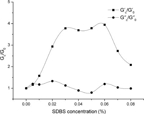
By plotting the value of the maximum in G′C/G′0 as a function of the corresponding SDBS concentration, it is shown that the growth rates of G′ are basically consistent. The storage modulus increased by nearly four times by adding the appropriate amount of SDBS, as seen in Figure 8. The optimal concentration of SDBS to reach the maximum depends on the concentration of BCG-1.

The value of the maximum in G′C/ G′0 evolution with sodium dodecyl benzene sulfonate (SDBS) concentration.
3.3 Effects of shear rate and SDBS on viscosity
The BCG-1 fluids are manifested to show the effect of shear thickening at low shear rates and subsequent shear thinning when the flow rate exceeded a point (Figure 9). The peak value of viscosity increased with rise in SDBS concentration. The viscosity at a surfactant concentration of 200 ppm and a shear rate 7.56 s-1 was above that before surfactant addition. However, when the SDBS concentration exceeded 400 ppm, the viscosity began to decrease. The dramatic increase in solution viscosity indicates the formation of a dynamic polymer network structure enhanced by hydrophobe/surfactant mixed micelles. This association structure is sensitive to the applied shear. As the rearranging of the micelles structure is induced at low shear, the shear thickening effect was noted. The micelles structure was disrupted by the increase of shear rate, which resulted in a consequent shear thinning.

Effect of shear rate and sodium dodecyl benzene sulfonate (SDBS) on viscosity of BCG-1. The BCG-1 loading is 3 g/l with 1% KCl and 0.05% ethylene diamine tetra acetic acid (EDTA) at 60°C.
A comparison of viscosity with shear rates at 7 s-1 and 170 s-1 reveals a striking difference in Figure 10, showing that even a small amount of SDBS can result in profound changes in the polymer solution viscosity. It reveals that the viscosity of the associating polymer/surfactant mixture is significantly higher than the associating polymer solution at low shear rate (7 s-1) and the viscosity can be increased by 1000%. This is appropriate for proppant suspension in static conditions. With the combination of surfactant, it will have similar proppant transport capability to crosslinked HPG gel. However, at high shear rate (170 s-1), it is rather the opposite. In the absence of surfactant, the viscosity was reduced to 50%, even when the surfactant concentration was considerably below Critical Micelle Concentration (CMC). This implies that BCG-1 solution is likely to be disposed of a special shearing resistance performance and low frictional resistance.

Effect of addition of sodium dodecyl benzene sulfonate (SDBS) on viscosity of the BCG-1 depending on the shear rate. The BCG-1 loading is 3 g/l with 1% KCl and 0.05% ethylene diamine tetra acetic acid (EDTA) at 60°C.
3.4 Sand sedimentation tests
The picture of the sand sedimentation tests is shown in Figure 11. These slurries exhibited satisfactory performance in the cylinder, but the BCG-1 gel had better static suspension properties. The proppant completely settled within 6 h in the HPG gel, whereas only a few particles settled in the BCG-1 gel. Although the HPG gel had a significantly higher viscosity (516 mPa·s at 170 s-1), the BCG-1 gel had better suspension properties (84 mPa·s at 170 s-1). These results again state clearly that the viscosity is not sufficient to characterize the proppant transport capability. The capability depends mainly on the microstructure.
![Figure 11: Proppant suspension in the cylinder (A) 0 h, (B) 4 h, (C) 6 h. [Left side cylinder of each picture: fluid system of 0.45% BCG-1 with 0.035% sodium dodecyl benzene sulfonate (SDBS), 1% KCl and 0.05% ethylene diamine tetra acetic acid (EDTA). Right side cylinder of each picture: fluid system of 0.35% hydroxypropyl guar gum (HPG) with 0.05% Na2CO3, 1% KCl and 0.5% crosslinker solution, pH10]; (D) image of crosslinked HPG gel.](/document/doi/10.1515/polyeng-2014-0344/asset/graphic/j_polyeng-2014-0344_fig_011.jpg)
Proppant suspension in the cylinder (A) 0 h, (B) 4 h, (C) 6 h. [Left side cylinder of each picture: fluid system of 0.45% BCG-1 with 0.035% sodium dodecyl benzene sulfonate (SDBS), 1% KCl and 0.05% ethylene diamine tetra acetic acid (EDTA). Right side cylinder of each picture: fluid system of 0.35% hydroxypropyl guar gum (HPG) with 0.05% Na2CO3, 1% KCl and 0.5% crosslinker solution, pH10]; (D) image of crosslinked HPG gel.
3.5 Residues particle size distribution evaluation
In order to reduce the fracturing fluid viscosity and clean the formation, gel breaker must be added. Ammonium persulfate is the most common gel breaker which can cleave the polymer into smaller fragments by producing free radicals. If the fragments are too big, insoluble residues will be produced. These insoluble residues will lead to damage of the conductive proppant pack and formation. HPG broken gel shows light yellow flocculent insoluble residues at the bottom of the beaker to the naked eye, whereas BCG-1 broken gel is clear and transparent, exhibiting no residue. The size distribution of broken polymer fragments of crosslinked HPG gel (0.4 w/v%) and BCG-1 (0.4 w/v%) solution is presented in Figure 12. Different residues particle size distribution of these two kinds of fracturing fluids is reported. The fragment sizes of HPG broken crosslinked gel ranged from 700 μm to 1100 μm. The fragments sizes of BCG-1 broken gel ranged from 1 μm to 400 μm and were monodisperse, exhibiting a unique peak. A large size of polymer fragments was measured for HPG broken gel. For the broken BCG-1 gel, there were no big fragments.
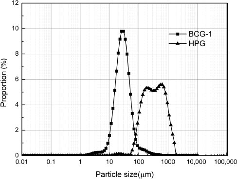
Particle size distribution of 0.4% hydroxypropyl guar gum (HPG) broken crosslinked gel and 0.4% BCG-1 broken gel.
3.6 Field-scale friction reduction evaluation
The field-scale friction reduction evaluation was performed at a 5000 m deep oil well of PetroChina Tarim Oilfield Company, which is representative of an actual fracturing treatment. The results of the test showed a low frictional resistance property (Table 2). The reduction rate of friction increased with pump displacement and reached 72.76% at 5.2 m3/min.
BCG-1 fracturing fluid reduction rate at different pump rates.
| Pump rate (m3/min) | Friction (MPa/2001.8 m) | Reduction rate (%) | |
|---|---|---|---|
| 0.4% BCG-1 fracturing fluid | Water | ||
| 2.3 | 10.7 | 4.06 | 62.06 |
| 3.2 | 20.23 | 6.65 | 67.13 |
| 4.3 | 32.79 | 9.75 | 70.03 |
| 5.2 | 47.44 | 12.92 | 72.76 |
3.7 Field implementation
The BCG-1 fracturing fluid has been applied in more than 400 wells in eight oilfields of China. Usage temperature ranged from 20°C to 150°C. Pilot trials verified that the BCG-1 fracturing fluid has low operating friction and a strong proppant carrying ability. More pilot trials are being performed to attract the attention of more oilfields.
4 Conclusion
A new fracturing fluid with a combination of hydrophobically associating polymer and anionic surfactant has been developed and successfully applied to the oilfield. This new fracturing fluid was established by hydrophobic association effect and a self-assembly process to form a network structure. The system shows particular shear thickening and reversible shear thinning rheological behavior. It has a simple composition, no residues, low operating friction and a strong proppant carrying ability. Conception of the proppant suspension property of a fracturing fluid lies in its network structure, which is validated by our work.
Acknowledgments
The authors wish to thank the Chengdu Baichun Petroleum Science and Technology Limited Company (Chengdu, P.R. China) for their joint sponsorship for this work.
References
[1] Risica D, Barbetta A, Vischetti L, Cametti C, Dentini M. Polymer 2010, 51, 1972–1982.10.1016/j.polymer.2010.02.041Search in Google Scholar
[2] Goel N, Shah SN, Grady BP. J. Pet. Sci. Eng. 2002, 35, 59–81.10.1016/S0920-4105(02)00164-XSearch in Google Scholar
[3] Wang S, Zhang Y, Guo J, Lai J, Wang D, He L, Qin Y. J. Pet. Sci. Eng. 2014, 124, 432–435.10.1016/j.petrol.2014.09.016Search in Google Scholar
[4] Cooke CE Jr. Soc. Pet. Eng. 1974, 27, 1273–1282.10.2118/5114-PASearch in Google Scholar
[5] Liu D, Fan M, Yao L, Zhao X, Wang Y. J. Pet. Sci. Eng. 2010, 73, 267–271.10.1016/j.petrol.2010.07.008Search in Google Scholar
[6] Khair EM, Shicheng Z, Shanbo M, Mei Z. J. Pet. Sci. Eng. 2011, 78, 131–138.10.1016/j.petrol.2011.05.011Search in Google Scholar
[7] Shaefer MT, Carman PS, Ngoma V. Soc. Pet. Eng. Conf. Pap. 2011.Search in Google Scholar
[8] Thomas A, Gaillard N, Favero C. Soc. Pet. Eng. Conf. Pap. 2013.Search in Google Scholar
[9] Gomaa AM, Gupta DVS, Carman P. Soc. Pet. Eng. Conf. Pap. 2014.Search in Google Scholar
[10] Guo Y, Liu J, Zhang X, Feng R, Li H, Zhang J, Lv X, Luo P. Energy Fuels 2012, 26, 2116–2123.10.1021/ef202005pSearch in Google Scholar
[11] Jian-xin L, Yong-jun G, Jun H, Jian Z, Xing L, Xin-ming Z, Xin-sheng X, Ping-ya L. Energy Fuels 2012, 26, 2858–2864.10.1021/ef3002185Search in Google Scholar
[12] Kuang W, Xia Y. Mater. Lett. 2014, 115, 109–112.10.1016/j.matlet.2013.10.034Search in Google Scholar
[13] Zhang L, Ming D, Shenwen F, Zhang P, Jian Z, Wang AF. J. Polym. Eng. 2011, 31, 37–44.Search in Google Scholar
[14] Su JL, Chu Q, Ren M. J. Polym. Eng. 2013, 2, 153–159.10.3917/rom.159.0153Search in Google Scholar
[15] Hourdet D, Ducouret G, Varghese S, Badiger MV, Wadgaonkar P. Polymer 2013, 54, 2676–2689.10.1016/j.polymer.2013.03.039Search in Google Scholar
[16] Wever DAZ, Picchioni F, Broekhuis A. Prog. Polym. Sci. Spec. Top.: Energy Relat. Mater. 2011, 36, 1558–1628.10.1016/j.progpolymsci.2011.05.006Search in Google Scholar
[17] Gouveia LM, Paillet S, Khoukh A, Grassl B, Müller AJ. Colloids Surf., A 2008, 322, 211–218.10.1016/j.colsurfa.2008.03.008Search in Google Scholar
[18] Li Y, Kwak JCT. Colloids Surf., A 2003, 225, 169–180.10.1016/S0927-7757(03)00353-4Search in Google Scholar
[19] Penott-Chang EK, Gouveia L, Fernández IJ, Müller AJ, Díaz-Barrios A, Sáez AE. Colloids Surf., A 2007, 295, 99–106.10.1016/j.colsurfa.2006.08.038Search in Google Scholar
[20] Onesippe C, Lagerge S. Carbohydr. Polym. 2008, 74, 648–658.10.1016/j.carbpol.2008.04.021Search in Google Scholar
[21] Gouveia LM, Müller AJ, Marchal P, Choplin L. Colloids Surf., A 2008, 330, 168–175.10.1016/j.colsurfa.2008.07.046Search in Google Scholar
[22] Li Y, Kwak JCT. Langmuir 2014, 20, 4859–4866.10.1021/la036331hSearch in Google Scholar PubMed
©2016 by De Gruyter
Articles in the same Issue
- Frontmatter
- Review
- Development of biomaterial surfaces with and without microbial nanosegments
- Original articles
- Performance and field implementation of a new fracturing fluid consisting of hydrophobically associating polyacrylamide and anionic surfactant
- Enhancing electrical and tribological properties of poly(methyl methacrylate) matrix nanocomposite films by co-incorporation of multiwalled carbon nanotubes and silicon dioxide microparticles
- The effect of two commercial melt strength enhancer additives on the thermal, rheological and morphological properties of polylactide
- Preparation and characterization of reactive liquid rubbers toughened epoxy-clay hybrid nanocomposites
- Catalytic growth of multi-walled carbon nanotubes using NiFe2O4 nanoparticles and incorporation into epoxy matrix for enhanced mechanical properties
- Enhanced carbon dioxide separation by polyethersulfone (PES) mixed matrix membranes deposited with clay
- Excellent durability of epoxy modified mortars in corrosive environments
- Engineering of silver nanoparticle fabricated poly (N-isopropylacrylamide-co-acrylic acid) microgels for rapid catalytic reduction of nitrobenzene
- High efficiency fabrication of ultrahigh molecular weight polyethylene submicron filaments/sheets by flash-spinning
- On the origin of indentation size effects and depth dependent mechanical properties of elastic polymers