Simulation of electrically controlled nematic liquid crystal Rochon prism
-
M. Buczkowska
 and
G. Derfel
and
G. Derfel

Abstract
Operation of an electrically controlled beam steering device based on Rochon prism made by use of nematic liquid crystal is modelled numerically. Deflection angles and angular distribution of light intensity in the deflected beam are calculated. Dynamics of the device is studied. Advantage of application of dual frequency nematic liquid crystal is demonstrated. Role of flexoelectric properties of the nematic is analyzed.
1 Introduction
Beam steering devices are used in applications where the light beam direction needs to be rapidly changed. Non-mechanical devices of this type are based on liquid crystals. They operate without need of application of mechanical force to move massive mirrors. They offer several advantages over the mechanical modulators, in particular no moving parts, low power consumption and low cost [1].
Nematic liquid crystals belong to materials which are often employed for non-mechanical beam steerers [2]. This is possible due to optical anisotropy of nematics determined by the refractive indices n‖ and n⊥, measured parallel and perpendicular to the director n, respectively. Interaction of nematic liquid crystals with the external electric field E results in torques acting on director. This allows to control the orientation of the optical axis by means of electric field and is basic for the beam steering and other applications.
The torques acting on the director are due to dielectric anisotropy, Δε = ε‖– ε⊥, and to flexoelectric properties [3]. The dielectric torques act in the whole volume of the sample and favor orientation n ‖ E if Δε > 0 and n ⊥ E if Δε < 0. The flexoelectric properties lead to the polarization of the nematic given by formula P = e11n(∇·n) – e33n × (∇ × n), where e11 and e33 are the flexoelectric coefficients. The flexoelectric torques act in the bulk and on the boundaries. When the nematic sample is subjected to the DC electric field, the director distribution results from joined action of the torques of both kinds. If AC voltage of sufficiently high frequency is applied, the flexoelectric contribution to the director distribution vanishes. Static director distributions in such AC field are not affected by the flexoelectric properties. They are induced solely by dielectric interactions. The director distributions at such high frequency AC field result from the effective electric field acting on liquid crystal which depends on the root mean square value of the bias voltage.
Several types of liquid crystal beam steerers can be distinguished, for instance the tunable gratings which employ diffraction of light and the devices in which refraction is used [4–8]. The refractive beam steerers operate like electrically controlled liquid crystal wedges or prisms. The deflection angles of the wedges are rather small due to small apex angles. Large deflection angles can be obtained if the light beam propagates along a thin liquid crystal layer and refracts or reflects at an oblique interface between two regions with different director orientations [9]. In this paper, we simulate numerically the nematic liquid crystal beam steering device which operates as an electrically controlled Rochon prism.
In the next section, Section 2, the structure of the modelled device is presented. Section 3 describes its principle of operation. Finally, a short discussion is provided in Section 4.
2 Model
The modelled structures are shown in Figure 1. Principle of their operation is explained for the case presented in Fig. 1(a).
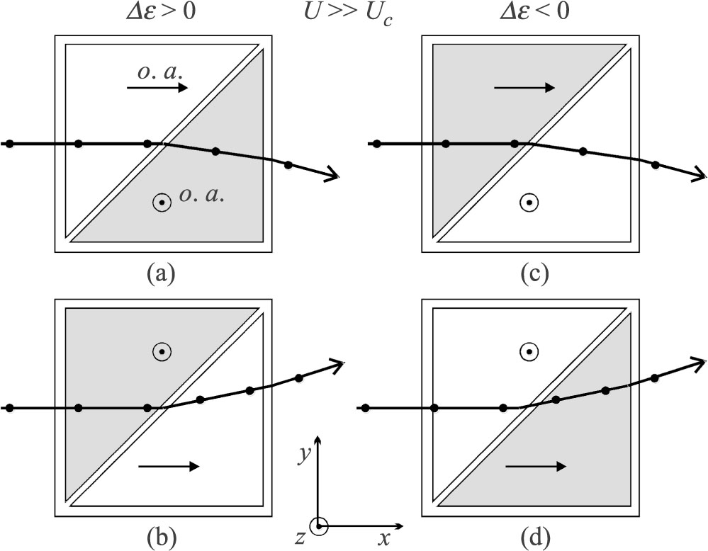
Principle of operation of the Rochon prism using the nematic liquid crystal shown for positive and negative dielectric anisotropy when U ≫ Uc. Shaded triangles mark the electrodes between which the voltage is applied. Directions of the optical axes (o. a.), as well as the polarization of light beams are indicated.
The modelled device consisted of the nematic liquid crystal layer of thickness d = 20 ¼m confined between two square glass plates positioned at z = ±d/2 of the Cartesian coordinate system xyz. Triangular transparent electrodes made of thin indium-tin oxide films were deposited on the inner surfaces of the plates. It was assumed that the orientation of the optical axis over the whole inner surfaces of the plates was imposed by the easy axes which were parallel to the xz plane and made the angle 0s = 0.1° with the xy plane. The interaction between the nematic material and the substrate was characterized by the surface anchoring energy, W. Two values of W were taken into account: W = 10–3 Jm–2 which ensured rigid surface orientation and W = 2.10–5 Jm–2 which allowed for field induced surface deformations. The model nematic liquid crystal was characterized by typical values of elastic constants, k11 = 6.10–12 N, k33 = 10.10–12 N, and of dielectric permittivity components ε‖ = 12, ε⊥ = 8. Its refractive indices were n‖ = 1.7925 and n22A5 = 1.5193. The presence of ions of concentration N = 1018 m–3 was taken into account. The quasi-blocking electrodes were assumed due to polyimide coatings [10].
In this way, the slab of uniaxial crystal with the optical axis oriented practically parallel to the incident beam was formed.
3 Principle of operation
As shown in Fig. 1(a), the light ray enters the first of two triangular parts of the layer. There is no voltage between the electrodes in this part. The optical axis is maintained by the aligning film. The light beam propagates along the x axis. If there were no voltage between the electrodes in the second triangular part, the incident light would run through the whole device without change of its direction. Application of electric field in the second triangular part changes the optical axis and affects the ray’s path.
If the AC voltage is applied, the flexoelectric properties are excluded and the influence of electric field is of purely dielectric nature. When RMS voltage exceeds the threshold value,
The incident ray polarized in the xy plane (i.e., with optical electric field vector parallel to z) passes through the first triangular prism as an ordinary ray. Propagation of this ray is then determined by the ordinary refractive index, no = n⊥. The angle of incidence on the boundary with the second prism is 45°. In the second prism, the same ray behaves as the extraordinary ray. Its propagation is determined by the extraordinary refractive index, ne, which depends on the orientation of the optical axis according to the formula
As ne(θ) ≠ n⊥, the ray refracts at the boundary between both prisms. (Reflection from the boundary is determined by the coefficient R ≈0.02.) For sufficiently high voltage, ne is practically equal to n‖ in the prevailing part of layer where θ = 90°. For n‖ = 1.7925 and n⊥ = 1.5193, the angle of refraction on the boundary between prisms equals 36.8° (which gives change of direction by 8.2°). Another refraction occurs at the exit from the device. The resulting deviation of the ray from its initial x direction is δ = 14.8°. Continuous curves in Figure 2 show distribution of the angles of deviation, δ(z), calculated for four values of voltage. It is evident that in order to deflect the prevailing part of the light beam, the bias voltage should significantly exceed the threshold value. After switching off the field, the anchoring and elastic torques restore the uniform director distribution in the whole slab and the deflection decays.
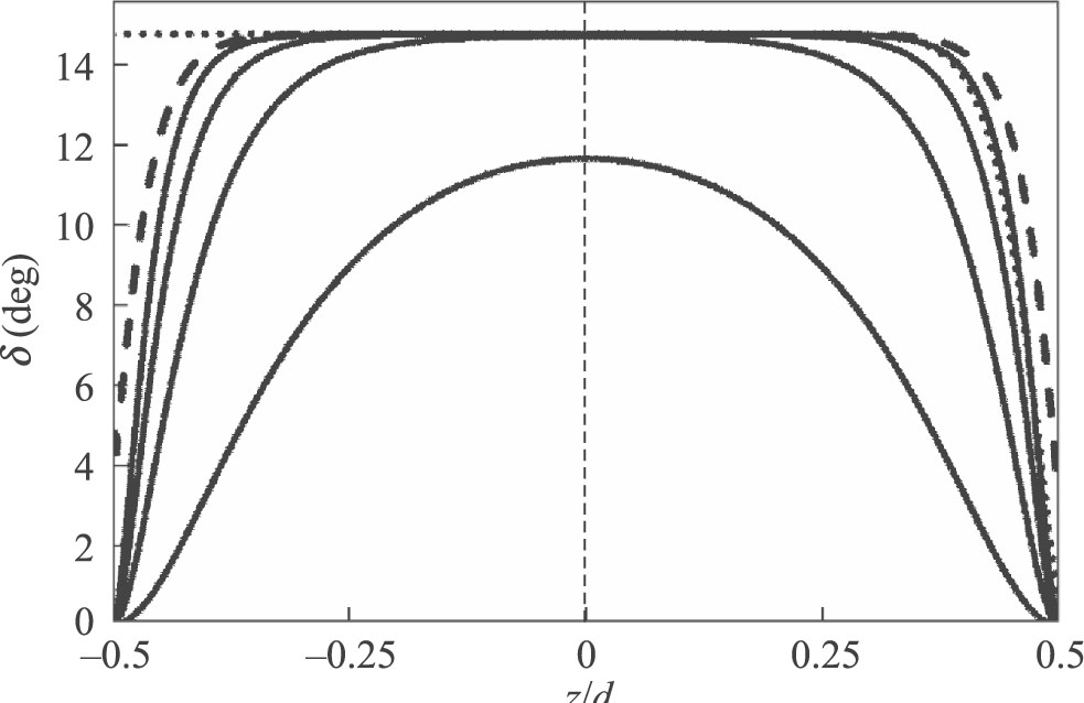
Deviation angle δ as a function of reduced coordinate z/d. RMS voltage values (in volts) are indicated at the curves. Continuous lines – purely dielectric interaction at low frequency AC voltage, W = 10–3 J/m2; dotted lines – joined dielectric and flexoelectric interactions at DC voltage, W = 2·10–5 J/m2, e11 + e33 = 40 pC/m; dashed line – purely dielectric interaction at low frequency AC voltage, W = 2·10–5 J/m2.
If the incident ray is polarized in the xz plane, it propagates as an ordinary ray in both parts of the device and does not change its direction.
Somewhat larger deflection angle can be obtained if the field is applied to the first triangular part of the device whereas the second part remains unaffected [Fig. 1(b)]. The light beam enters the nematic in which the optical axis is parallel to z. The ray polarized in the xy plane propagates as the extraordinary ray. It refracts in the second part of the device where its propagation is determined by n⊥ since the optical axis is parallel to x. The resulting deviation angle is δ = -17.7°. Figures 1(a) and 1(b) show that if the triangles subjected to the field are interchanged then the ray changes its direction by 32.5°.
If the incident ray is polarized in the xz plane, it behaves like an extraordinary ray in both parts of the device and is not deflected.
The angular intensity distributions of the emerging beams considered above is shown in Fig. 3 as a function of the deviation angle.
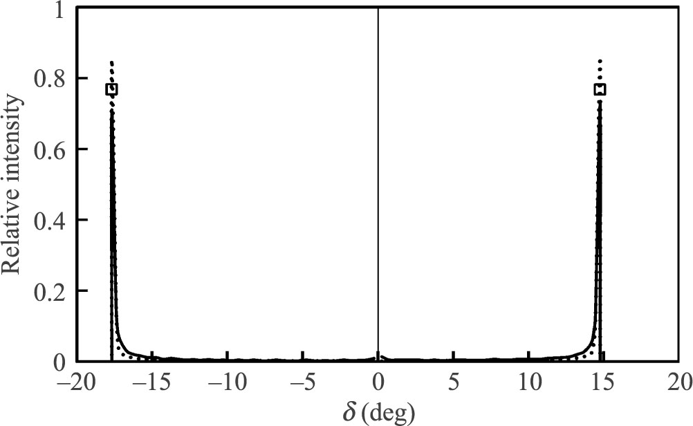
Intensity distribution in the emerging beams calculated as a function of the deviation angle for two variants of the Rochon prism shown in Figs. 1(a) and 1(b), U = 10V. Continuous lines – purely dielectric interaction at low frequency AC voltage, W = 10–3 J/m2; dotted lines – joined dielectric and flexoelectric interactions at DC voltage, W = 2·10–5 J/m2, e11 + e33 = 40 pC/m. Empty squares mark the maxima of intensity for low frequency AC voltage and W = 2·10–5 J/m2.
Some improvement of the angular distribution of the intensity of deflected beams can be obtained due to flexoelectric properties. This effect is possible under DC voltage if the surface anchoring is sufficiently weak. The director adjacent to the boundaries may then deviate from the easy axes. For W = 2·10–5 J/m2 and e11 + e33 = 40 pC/m, the threshold voltage is Uc = 1.26 V. The resulting director profiles are asymmetric. The optical axis is parallel to the z axis in the whole negative half of the layer due to the flexoelectric torques. As a result, the deflecting part of the prism is thicker as shown in Fig. 2 by a dotted curve. This gives larger intensity of the emerging beam as shown by dotted lines in Fig. 3.
When the surface anchoring is weak as previously but the AC voltage is applied, the deformation is of purely dielectric nature and arises above Uc = 1.18 V. The distribution of the angles of deflection for U = 10 V is shown in Figure 2 by a dashed line. The intensity of the deflected beam is lower than in the DC case as it is marked by small squares in Fig. 3.
The layer thickness limits the width of the light beam which can be steered. However the time necessary for optical axis reorientation is proportional to square of the thickness. Therefore, the layer should be as thin as possible for a given application of the device or the bias voltage should be high enough.
In order to determine the dynamics of the device, the director orientation angle θ(z, t) was computed as a function of time after switching on and after switching off the voltage U = 10 V by means of method described in Ref. 13. The viscous torque exerted on the director was determined by the rotational viscosity γ1 = 0.076 Nsm–2. Figure 4 illustrates the dynamics of deflection of the ray for the case shown in Figure 1a. The deviation angle δ is plotted as a function of time after application of a voltage rectangular pulse of height of U = 10 V and duration of 0.5 s. It is evident that the voltage induced deflection arises during ca. 0.08 s whereas it decays during much longer time (ca. 1.5 s).
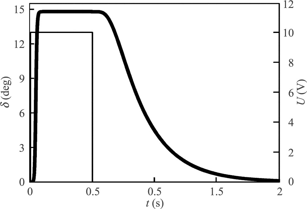
Deviation angle (thick line, left scale) as a function of time after application of a 0.5 s long pulse of low frequency AC voltage. Thin line represents the RMS value of bias voltage, right scale.
The reorientation time after switching off the field can be shortened if a dual frequency liquid crystal is used. For such material, the dielectric anisotropy is positive for low frequencies (of the order of several kHz) and negative for high frequencies (at several tens of kHz) [14]. Thus, the high frequency signal of sufficient magnitude quickly restores the planar orientation and makes it uniform over the whole device. This effect is illustrated in Fig. 5. The deviation angle decays to zero during ca. 0.05 s after increase of frequency. Dotted lines show that dynamics of the deviation angle is practically not affected by the flexoelectric properties.
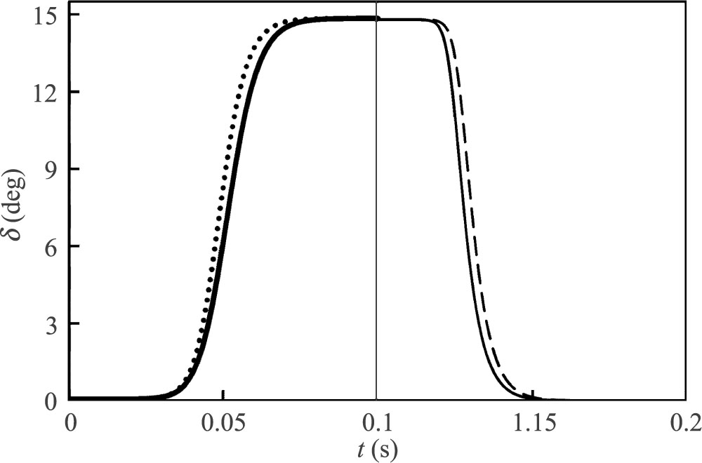
Deviation angle as a function of time during application of 10 V RMS voltage to the layer filled with dual frequency nematic. Vertical line marks the moment when the frequency of bias voltage is rapidly increased. Low frequency AC and DC voltage corresponds to Δε = 4 and high frequency AC to Δε = –4. Thick continuous line: purely dielectric interaction, low frequency AC, Δε = 4, W = 10–3 J/m2. Thin continuous line: purely dielectric interaction, high frequency AC, Δε = –4, W = 10–3 J/m2. Dotted line: joined dielectric and flexoelectric interactions in DC field, W = 2·10–5 J/m2, Δε = 4, e11 + e33 = 40 pC/m. Dashed line: purely dielectric interaction at high frequency AC voltage, Δε = –4, W = 2·10–5 J/m2.
4 Discussion
The same results can be obtained if the surface alignment imposes the nearly homeotropic orientation, i.e., with n nearly perpendicular to the plates, with small deviation towards x. Under the action of high frequency AC voltage, the optical axis in the first triangular area becomes parallel to the x axis due to Δε < 0. In this way the Rochon prism is formed, as in the previous case [Fig. 1(c)], however the useful asymmetry of the director profile due to flexoelectric torque is absent. Low frequency voltage, for which Δε > 0, restores the homeotropic orientation. (Flexoelectric torques available under DC voltage do not favour the homeotropic alignment.) Alternative variant with the optical axis perpendicular to the plates in the first triangular part and with its field induced planar orientation in the second part is also possible [Fig. 1(d)].
The deformations considered above were simulated by means of approach applied earlier to the case of DC electric field, [10–12], which is justified by the fact that the dielectric deformations have the same form for AC and DC fields. The results are valid for the case of AC voltage, provided that the RMS value of AC voltage is equal to the value of DC voltage and that the frequency of the applied voltage exceeds the relaxation frequency of the ionic space charge which allows to ignore the transport of ions [15].
5 Conclusions
The above considerations were based on geometrical optics which is suitable for demonstration of operating principle of the device. When the light beam propagates through the nematic liquid crystal, scattering occurs due to director fluctuations. One may expect that this effect leads to significant reduction of the beam intensity. However, there are examples which show that scattering does not exclude proper working of such beam steering device, provided that the path length of the ray in the nematic is of the order of 1 mm [16]. Another effect which can be expected because of the scattering is depolarization of partially coherent light passing through liquid crystals [17]. It is due to a phase shift between linearly polarized components of the light beam. The depolarization depends on the coherence length of light and on birefringence of the medium. For the partially coherent light with short coherence length, the phase shift may be so high that the light passing through liquid crystal may be almost totally unpolarized. However in our case only one component propagates through the device, with polarization parallel or perpendicular to the optical axis, therefore, one may suppose that the degree of polarization will not be affected significantly.
References
1 P.F. McManamon, P.J. Bos, M.J. Escuti, J. Heikenfeld, S. Serati, H. Xie, and E.A. Watson “A review of phased array steering for narrow-band electrooptical systems”, Proc. IEEE 97, 1078–1096 (2009).10.1109/JPROC.2009.2017218Search in Google Scholar
2 S.-T. Wu and D.-K. Yang, Fundamentals of Liquid Crystal Devices, John Wiley & Sons, Chichester, 2006.10.1002/0470032030Search in Google Scholar
3 L.M. Blinov, Structure and properties of liquid crystals, Springer, New York, 2011.10.1007/978-90-481-8829-1Search in Google Scholar
4 T. Chan, E. Myslivets, and J.E. Ford, “2-Dimensional beamsteering using dispersive deflectors and wavelength tuning”, Opt. Express 16, 14617–14628 (2008).10.1364/OE.16.014617Search in Google Scholar
5 J. Kim, C. Oh, M.J. Escuti, L. Hosting, and S. Serati, “Wide-angle, nonmechanical beam steering using thin liquid crystal polarization gratings”, Proc. of SPIE 7093, 709302-1709302-12 (2008).10.1117/12.795752Search in Google Scholar
6 S. Valyukh, V. Chigrinov, H.S. Kwok, and H. Arwin, “On liquid crystal diffractive optical elements utilizing inhomogeneous alignment”, Opt. Express 20, 15209–15221 (2012).10.1364/OE.20.015209Search in Google Scholar PubMed
7 S. Valyukh, I. Valyukh, and V. Chigrinov, “Liquid-crystal based light steering optical elements”, Photon Lett Pol. 3, 88–90 (2011).10.4302/plp.2011.2.15Search in Google Scholar
8 A.B. Golovin, S.V. Shiyanovskii, and O.D. Lavrentovich, “Gradient beam steering device based on nematic cell with continuous ramp of the phase retardation”, Proc. of SPIE 5741, 146–153 (2005).10.1117/12.588640Search in Google Scholar
9 S.R. Davis, G. Farca, S.D. Rommel, A.W. Martin, and M.H. Anderson, “Analog, non-mechanical beam-steerer with 80 degree field of regard”, Proc. of SPIE 6971, 69710G-1-69710G-11 (2008).10.1117/12.783766Search in Google Scholar
10 G. Derfel and M. Buczkowska, “Flexoelectric deformations of homeotropic nematic layers in the presence of ionic conductivity”, Liq. Cryst. 32, 1183–1190 (2005). doi:10.1080/02678290500284405.Search in Google Scholar
11 G. Derfel, “Numerical study of ionic current in dielectric liquid layer subjected to AC voltage”, J. Mol. Liq. 144, 59–64 (2009).10.1016/j.molliq.2008.10.007Search in Google Scholar
12 M. Buczkowska, “Numerical analysis of deformations induced by dc electric field in homeotropic nematic layers with giant flexoelectricity”, Mol. Cryst. Liq. Cryst. 543, 48–56 (2011).10.1080/15421406.2011.568328Search in Google Scholar
13 G. Derfel and M. Buczkowska, “Dynamics of electric field induced deformations in flexoelectric nematic layers”, Liq. Cryst. 40, 272-280 (2013).10.1080/02678292.2012.740507Search in Google Scholar
14 H. Xianyu, S.-T. Wu, and C.-L. Lin, “Dual frequency liquid crystals: a review”, Liq. Cryst. 36, 717–726 (2009).10.1080/02678290902755598Search in Google Scholar
15 M. Buczkowska and G. Derfel, “Role of flexoelectricity in electro-optical properties of hybrid aligned nematic layers”, Appl. Phys. Lett. 103, 211115-1-211115-4 (2013).10.1063/1.4832858Search in Google Scholar
16 O.P. Pishnyak and O.D. Lavrentovich, “Electrically controlled negative refraction in a nematic liquid crystal”, Appl. Phys. Lett. 89, 251103-1 – 251103-3 (2006).10.1063/1.2408658Search in Google Scholar
17 A.W. Domanski, D. Budaszewski, M. Sierakowski, and T.R. Wolinski, “Depolarization of partially coherent light in liquid crystals”, Opto-Electron. Rev. 14, 305–310 (2006).10.2478/s11772-006-0041-xSearch in Google Scholar
© 2016 SEP, Warsaw
This article is distributed under the terms of the Creative Commons Attribution Non-Commercial License, which permits unrestricted non-commercial use, distribution, and reproduction in any medium, provided the original work is properly cited.
Articles in the same Issue
- Research Article
- Simulation of electrically controlled nematic liquid crystal Rochon prism
- Research Article
- Optical diagnostics of a single evaporating droplet using fast parallel computing on graphics processing units
- Research Article
- Spatiotemporal multiplexing method for visual field of view extension in holographic displays with naked eye observation
- Research Article
- The polymer converter for effectively connecting polymer with silica optical fibres
- Research Article
- The laboratory investigation of the innovative sensor for torsional effects in engineering structures’ monitoring
- Research Article
- Recent advancements in the “water-window” microscopy with laser-plasma SXR source based on a double stream gas-puff target
- Research Article
- Up-conversion luminescence in germanate glass and double-clad optical fibre co-doped with Yb3+/Eu3+ ions