Side-pumped neodymium laser with self-adaptive, nonreciprocal cavity
-
 ,
,

We demonstrate the generation of a near-diffraction-limited beam in a diode-side-pumped Nd:YAG slab laser with a nonreciprocal, self-adaptive cavity. The energy output of 228 mJ with 17.2% slope efficiency and 17.3% optical-to-optical efficiency was obtained.
1. Introduction
The near infrared laser sources are very attractive devices which are widely used in the industry, healthcare, environmental monitoring and military. However, certain particular applications like, i.e., remote sensing or target designation require high-energy output of order of few hundreds of mJs with diffraction-limited beam quality. In order to meet those conditions, a special approach in the laser construction must be done. The progress done in recent years in 2D laser diode arrays development enabled to build compact side-pumping modules which can provide tens of kWs of peak power confined to a few square millimetres area. On the other hand, intensive pumping and heat dissipation induce strong thermal effects which favour generation in higher transverse modes. Additionally, it significantly degrades the spatial quality and decreases the overall performance of the laser system. There are several techniques, i.e., injection-seeding [1,2], grazing-incidence-angle [3,4] or self-adaptive resonators based on phase conjugation via gain saturation mechanism [5–15], that allow to generate near-diffraction-limited beam output in the presence of a high inhomogeneity of the gain spatial profile. In this paper we demonstrate the results of a self-adaptive Nd:YAG laser with intra-cavity amplifier with an open-loop, nonreciprocal cavity containing phase conjugate mirror.
2. Principle of operation
The self-adaptive resonator scheme is depicted in Fig. 1. Initially it is an open-loop cavity without any feedback. The intra-cavity waves develop from the spontaneous emission. Due to the gain saturation mechanism in the main head, waves E1 and E3 interfere constructively in the gain medium (intersecting under θ angle which determines the gain-frin-ges period) forming a transmissive gain grating, whereas E2 and E3 form a reflective gain grating. The phase conjugate E4 wave [see Eq. (1)] is generated as a consequence of the diffraction of the E1 and E2 on reflective and transmissive gratings, respectively
E4 propagates in the resonator and converts to E2 and E1. As soon as the gain-hologram is written in the active medium and the threshold condition is fulfilled, this process builds up to a point, when the phase conjugate mirror (PCM) is formed as a result of nondegenerate four-wave mixing mechanism inside an active medium. The two polarizers, a half wave plate and a Faraday rotator create a nonreciprocal transmission element (NRTE) which allows to regulate the amplitude of counter-propagating waves, thus to control of the diffraction efficiency of the gain gratings and to prevent the saturation of the amplifier by a counter-propagating wave. The PCM provides feedback, closes the loop and cancels the wavefront aberrations. Once the gain saturates, the diffraction efficiency of the gain grating significantly decreases and the output is generated as a series of a few hundred-ns-long pulses. In a certain, particular case, the gathered energy can be extracted in a single, few- -tens to hundred nanoseconds pulse with near-diffraction-limited quality [10]. Hence, the gain gratings dynamics behave as a passive Q-switch. Furthermore, it acts as a spectral filter, as well. When certain conditions are met, only one longitudinal, fundamental mode is generated and laser operates in a single frequency regime. According to Ref. 9, in order to overcome the generation threshold, the small-signal gain has to be g0L ≥ 8.5. The main amplifier provided gain product of 7.2. We increased it by introduction of an additional amplifying stage (AMP), which will be described later.
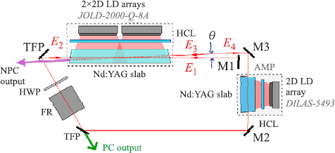
Scheme of the self-adaptive nonreciprocal cavity: TFP – thin-film polarizer; HCL – cylindrical lens; HWP – half wave plate; FR – Faraday rotator; θ – beam intersection angle; green arrow – phase-conjugate output, purple arrow – non-phase conjugate out-put; AMP – amplifying stage.
3. The Nd:YAG laser setup
The 1% at. Nd:YAG single crystal with dimensions of 4×4×72 mm3 was applied as a gain medium in the laser oscillator head. Both 4×4 mm2 facets were anti-parallel bevelled under 1° angle in order to prevent the spontaneous emission amplification. The pumping module consisted of two 2D laser diode arrays (Jenoptik JOLD-2000-Q-8A) and a single cylindrical lens (f = 16 mm). The emitters bars did not have fast-axis-collimation lenses. The emission wavelength stabilized at 20°C was measured to be 808 nm (FWHM = 3 nm). For a pump duration tp = 0.25 ms and repetition rate PRF = 2 Hz, the maximum combined pump energy was slightly above 1J. The pump radiation was confined inside the gain medium to a 60 mm-wide, 2.5 mm- -high and 4 mm-deep excited area.
The amplifying stage consisted of the 1% at. Nd:YAG gain medium (4×4×25 mm3, facets bevelled under 2°) pumped with a single, fast-axis-collimated 2D laser diode array (DILAS-5493). The pump radiation was tightly focused by means of a single cylindrical lens (f =50 mm). Resulting excited volume in the active medium was 14.3×0.25×4 mm3. The emission wavelength stabilized at 25°C was measured to be 808 nm (FWHM = 2.4 nm). The pump source provided up to 0.5 J of energy in a 0.25 ms duration. Total resonator length was Lrez = 3.3 m. Due to a very low repetition rate of 2 Hz, the influence of thermal effects was neglected.
4. Experimental results
4.1. Diode-pumped Nd:YAG self-adaptive oscillator
The experiments were carried out in a laser with the amplifying stage (AMP) turned off. The pump duration measured at full width at half maximum was tp = 0.25 ms (FWHM). The energetic characteristics measured for different beam intersection angles θ is shown in Fig. 2.
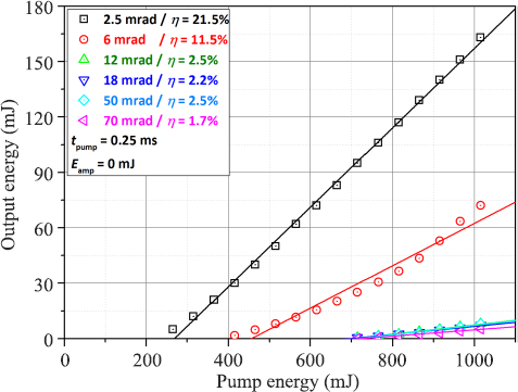
Output energy vs. pump energy of laser oscillator for different beam intersection angles
This angle should be minimized, however, too low value, in the presence of high gain, will cause parasitic lasing due to feedback provided by mirror M3. In our case, the best results were achieved for θ = 2.5 mrad. The longest interference path contributes to decrease of the threshold and to increase of the gain grating diffraction efficiency. Output energy of Eout = 163 mJ with slope efficiency η = 21.5% and optical-to-optical efficiency 17.2% were achieved. For beam intersection angle above 12 mrad, slope efficiency was very low and remained below 3%. The time trace of output pulse (registered with Thorlabs DET025AFC 2 GHz photodiode) is depicted in Fig. 3.
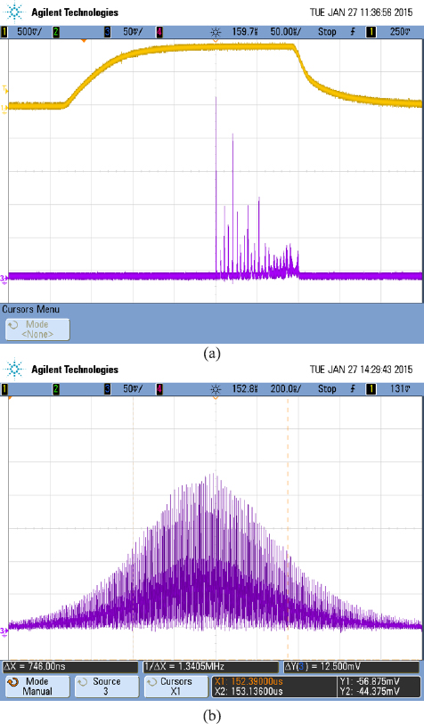
Time trace of output pulse in relation to pump pulse (purple – laser; yellow – pump).
Figure 3(a) shows an oscillogram of output pulse burst. It can be explained as follows: high gain allows the gain grating to build up very fast, what in consequence increases its diffraction efficiency. The threshold is quickly overcome and the first pulse is generated. The upper laser level is depopulated and since there is enough gain provided by the pump, the scheme repeats itself and continues to generate other pulses in the series, until the pump is depleted. The generation of series of pulses was accompanied by a strong temporal and energetic jitter. Figure 3(b) depicts first pulse in the series. It was strongly modulated due to multimode generation. The contrast of the population grating was too low to provide desired mode selectivity. The pulse width measured at FWHM was of 746 ns. The change of the retardation introduced by wave plate did not enforce single pulse generation. It decreased the energy output and increased the threshold. Reducing pump energy to 190 mJ allowed inefficient generation of a single pulse with energy of only Ep = 1.1 mJ. The beam intensity spatial profile (Thorlabs BP-106 VIS CCD Beam Profiler) registered in far field is shown in Fig. 4.
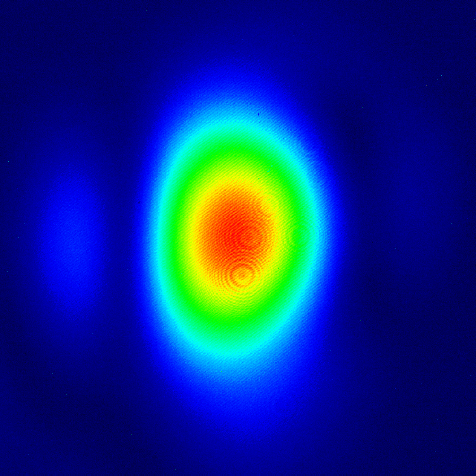
Beam intensity spatial profile for θ = 2.5 mrad.
The generated beam was astigmatic with an elliptical profile. The beam quality parameter M2 was measured to be 2.6 and 2.5 whereas the full divergence angle was 1.4 mrad and 1.9 mrad in X and Y planes, respectively. The change of the beam intersection angle up to 40 mrad did not significantly influence on the spatial quality. Above that value, the generation of higher transverse modes was obtained.
4.2. Diode-pumped Nd:YAG amplifier
In the next step the amplifying stage was incorporated (see Fig. 1). The pump duration was set to tamp = 0.15 ms. The delay between the amplifier and oscillator pump pulses was optimized to achieve highest pulse energy at the output. The pump energy of the oscillator remained at the maximum value. The output energy vs. total pump energy plots measured for different beam intersection angles are depicted in Fig. 5. Due to technical limitations of the laser diode driver we were unable to decrease the pump current below 100 A, thus the minimal combined pumping energy was approx. 1.1 J.
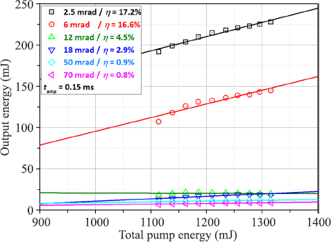
Output energy vs. total pump energy of the laser with amplifier for different beam intersection angles.
For beam intersecting at angle of 2.5 mrad, energy output of 228 mJ with a 17.2% slope efficiency and a 17.3% optical-to-optical efficiency was obtained. The output time trace consists of a pulse burst followed by a quasi-cw generation [see Fig. 6(a)].
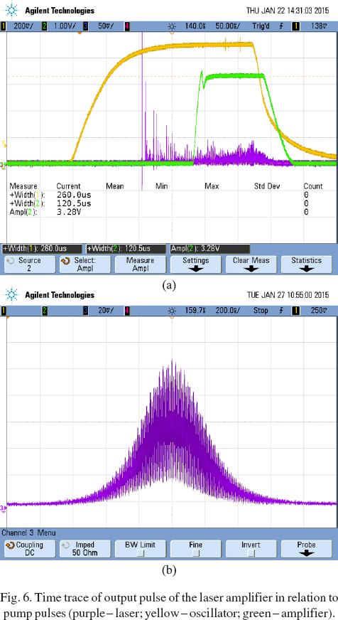
Time trace of output pulse of the laser amplifier in relation to pump pulses (purple – laser; yellow – oscillator; green – amplifier).
Although the gain is higher (as well as the gain grating contrast), the grating dynamic and a low generation threshold did not allow to generate a single pulse. The effect saturates relatively fast and gain grating stops behaving as a Q-switch and favours q-cw generation. The first pulse in the series is less modulated [Fig. 6(b)vs. Fig. 3(b)] and its duration was measured to be 425 ns. The change of the wave plate retardation did not enforce single pulse generation. It influences only on the threshold and the efficiency. The beam intensity spatial profile (Thorlabs BP-106 VIS CCD Beam Profiler) registered in far field is shown in Fig. 7.
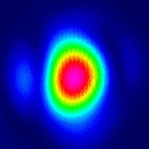
Beam intensity spatial profile of a laser amplifier for θ = 2.5 mrad.
The beam quality parameter M2 did not change significantly. It was measured to be 2.5 and 2.4 in X and Y planes, respectively. Beam divergence remained unchanged.
5. Conclusions
We demonstrate a self-adaptive, nonreciprocal, open-loop Nd:YAG laser amplifier. In the experiments 228 mJ of output energy with a 17.8% slope efficiency was achieved. The NRTE did not enforce a single longitudinal mode in the cavity, hence each resonator mode forms own gain grating, what in turn creates a complex volumetric structure. The change of the wave plate retardation had no impact on the mode selection in the cavity. It only influenced on the threshold and efficiency of the laser. The optimization of the mode size and the overlap between interfering beams should increase the energy extraction efficiency. However, in the presence of high inhomogeneity of spatial gain distribution we managed to obtain near-diffraction-limited output with M2 parameter less than 2.5. In order to achieve an efficient, high-performance, high-energy and near-diffraction-limited quality, self-adaptive laser system, it is crucial to provide a single intra-cavity mode.
Acknowledgements
This work was supported by the Polish National Science Centre under the Project No. NCN2012/05/B/ST7/00088.
References
1 A.D. Farinas, E.K. Gustafson, and R.L. Byer, “Design and characterization of a 5.5-W, cw, injection-locked, fibre-coupled, laser-diode-pumped Nd:YAG miniature-slab laser”, Op Lett.19, 114–116 (1994).10.1364/OL.19.000114Search in Google Scholar
2 R.F. Teehan, J.C. Bienfang, and C.A. Denman, “Power scaling and frequency stabilization of an injection-locked Nd:YAG rod laser”, Appl. Opt.39, 3076–3084 (2000).10.1364/AO.39.003076Search in Google Scholar PubMed
3 G.M. Thomas and M.J. Damzen, “Passively Q-switched Nd:YVO4 laser with greater than 11W average power”, Opt. Exp.19, 577–4582 (2011).Search in Google Scholar
4 M. Kaskow, W. Zendzian, and J.K. Jabczynski, “Near-diffraction-limited, high peak power, electro-optically Q-swit-ched, diode-side-pumped Nd:YVO4 grazing-incidence oscillator”, Opt. Laser Techn.65, 50–55 (2015).10.1016/j.optlastec.2014.06.013Search in Google Scholar
5 O. L. Antipov, D.V. Chausov, A.S. Kuzhelev, V.A. Vorobev, and A.P. Zinoviev, “250-W average-power Nd:YAG Laser with self-adaptive cavity completed by dynamic refractive- -index gratings”, IEEE J. Quantum Electron.37, 716–724 (2001).10.1109/3.918586Search in Google Scholar
6 M.J. Damzen, R.P.M. Green, and K.S. Syed, “Self-adaptive solid-state laser oscillator formed by dynamic gain-grating holograms”, Opt. Lett.20, 1704–1706 (1995).10.1364/OL.20.001704Search in Google Scholar
7 P. Sillard, A. Brignon, and J.-P. Huignard, “Loop resonators with self-pumped phase-conjugate mirrors in solid-state saturable amplifiers”, J. Opt. Soc. Am. B14, 2049–2058 (1997). 10.1364/JOSAB.14.002049Search in Google Scholar
8 P. Sillard, A. Brignon, J.-P. Huignard, and J.-P. Pocholle, “Self-pumped phase-conjugate diode-pumped Nd:YAG loop resonator”, Opt. Lett.23, 1093–1095 (1998).10.1109/CLEOE.1998.719533Search in Google Scholar
9 P. Sillard, A. Brignon, and J.P. Huignard, “Gain-grating analysis of a self-starting self-pumped phase-conjugate Nd:YAG loop resonator”, IEEE J. Quantum Electron.34, 465–472 (1998).10.1109/3.661454Search in Google Scholar
10 R. Soulard, A. Brignon, S. Raby, E. Durand, and R. Mon- corge, “Diode-pumped Nd:YAG self-adaptive resonator with a high gain amplifier operating at 100 Hz”, Appl. Phys. B106, 295–300 (2012).10.1364/CLEO.2010.CTuQQ3Search in Google Scholar
11 T.T. Basiev, A.V. Gavrilov, M.N. Ershkov, S.N. Smetanin, A.V. Fedin, K.A. Bel’kov, A.S. Boreisho, and V.F. Lebedev, “Loop laser cavities with self-pumped phase-conjugate mirrors in low-gain active media for phase-locked multichannel laser systems”, Quantum Electron.41, 207–211 (2011).10.1070/QE2011v041n03ABEH014491Search in Google Scholar
12 A.P. Pogoda, T.B. Lebedeva, M.R. Yusopov, M.R. Liven- tsov, V.F. Lebedev, A.S. Boreysho, A.V. Gavrilov, S.N. Smetanin, and A.V. Fedin, “High power Nd:YAG laser with self-pumped phase-conjugate loop cavity and repetitive pulsed diode-matrix side-pumping”, Proc. SPIE8677, 86770Z (2013)10.1117/12.2016458Search in Google Scholar
13 Z. Sun, Q. Li, Q. Cheng, M.J.H. Lei, and Y. Hui, “Efficient continuous diode-pumped Nd: YVO4 slab laser with an opened-loop reciprocal dynamic holographic cavity”, Zhongguo Jiguang/Chinese Journal of Lasers41, 0702003 (2014).Search in Google Scholar
14 W. Zendzian, J.K. Jabczynski, M. Kaskow, L. Gorajek, J. Kwiatkowski, and K. Kopczynski, “250 mJ, self-adaptive, diode-side-pumped Nd:YAG slab laser”, Opt. Lett.37, 2598–2600 (2012).10.1364/OL.37.002598Search in Google Scholar PubMed
15 M. Kaskow, W. Zendzian, J.K. Jabczynski, L. Gorajek, and M. Piasecki, “Passively Q-switched Nd:YAG laser with diffractive output resonator”, Laser Phys. Lett.11, 115813 (2014)10.1088/1612-2011/11/11/115813Search in Google Scholar
© 2016 SEP, Warsaw
This article is distributed under the terms of the Creative Commons Attribution Non-Commercial License, which permits unrestricted non-commercial use, distribution, and reproduction in any medium, provided the original work is properly cited.
Articles in the same Issue
- Article
- Polymer substrates for flexible photovoltaic cells application in personal electronic system
- Article
- Characteristics of nanostructure dye-sensitized solar cells using food dyes
- Article
- Analysis of surface properties of semiconducting (Ti,Pd,Eu)Ox thin films
- Article
- Internal quantum efficiency improvement of InGaN/GaN multiple quantum well green light-emitting diodes
- Article
- Side-pumped neodymium laser with self-adaptive, nonreciprocal cavity
- Article
- Influence of doping on the performance of GaAs/AlGaAs QWIP for long wavelength applications
- Article
- Low-temperature growth of GaSb epilayers on GaAs (001) by molecular beam epitaxy