Designing the response-spectra of microwave metasurfaces: theory and experiments
-
Yixiang Xu
 ,
Yufei Song
,
Yufei Song
 ,
Zhuo Wang
,
Zhuo Wang

Abstract
Metasurfaces composed by arrays of coupled plasmonic resonators have attracted tremendous attention due to their extraordinary abilities to manipulate electromagnetic (EM) waves. However, existing theories for such systems are either empirical with model parameters obtained by fitting with simulations, or can only be applied to high-frequency systems where metals exhibit finite permittivity. Here, we extend our recently established leaky-eigenmode (LEM) theory to the microwave regime where metals exhibit infinite permittivity, with all parameters directly computable without fitting procedures. After validating our theory with both simulations and experiments on a benchmark metasurface, we illustrate how to utilize the theory to guide designing microwave metasurfaces with freely tailored line-shapes, including particularly the generation of a bound state in the continuum. All theoretical predictions are verified by experiments and simulations. Our study provides a powerful tool to guide designing functional microwave meta-devices for various applications.
1 Introduction
Manipulating electromagnetic (EM) waves at will is highly desired in information science and applications. However, EM devices made by conventional dielectrics are too bulky in sizes and exhibit limited wave-control functionalities, as they typically rely on propagating phases of EM waves traveling inside the devices. Metasurfaces [1], [2], [3], ultrathin metamaterials constructed by arrays of subwavelength planar microstructures (e.g., “meta-atoms”) with tailored EM responses, offer an ultra-thin and powerful platform to control EM waves. Many fascinating wave-manipulation effects were demonstrated based on metasurfaces in different frequency domains [4], [5], [6], [7], [8], [9], [10], [11], [12], [13]. Metasurfaces composed by meta-units containing multiple coupled resonators (see Figure 1a and b) have attracted much attention recently, since couplings among constitutional resonators offer more degrees of freedom to control EM waves [14], [15], [16], [17], [18]. For example, via tailoring the “couplings” between meta-atoms, we can design metasurfaces exhibiting unusual optical line-shapes such as Rabi splitting [19], [20], [21], Fano resonances [22], [23], [24], bound states in continuum (BIC) [25], [26], [27], [28], [29], [30], [31], and so on [32], [33], [34].
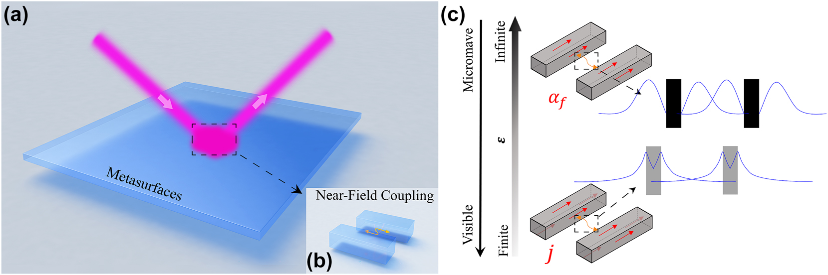
Coupled meta-atoms in metasurfaces: near-field coupling and permittivity properties across visible and microwave regimes. (a) Metasurfaces with complex meta-atoms composed by multiple metallic resonanors where (b) the near-field coupling between inter-resonators playing important role on its optical response. (c) Schematics of permittivity property of metallic resonator at visible and microwave regime where the near-field behavior are determined by body currents j and surface currents α f , respectively. The top and bottom insets on the right side of Figure 1c illustrate the different near-field distribution between two resonators at low-frequency and high-frequency, respectively.
Despite of many fascinating effects discovered, however, theoretical tools to guide designing such metasurfaces are insufficiently developed. Full-wave simulations, though being accurate in reproducing experimental results, offer less insights to help understand the intrinsic physics. While theoretical models, including the coupled-mode theory (CMT) [35], [36], [37], [38], Fano’s formula [15], [16] and effective circuit models [17], [18], are intuitive to help understand the intriguing phenomena discovered, they unfortunately require parameter-fitting procedures and thus cannot predict unknown phenomena before numerical simulations are performed. Very recently, based on leaky-eigenmode (LEM) expansions, we established a rigorous theoretical framework to predict the optical response spectra of arbitrarily coupled systems [18], with all involved parameters computed directly without fitting procedures. Assisted with the LEM theory, we can design coupled plasmonic metasurfaces with appropriate inter-resonator couplings so as to exhibit desired optical line-shapes, including BIC [39], achromatic no-reflection [17], and freely tailored angular dispersions [40].
However, the LEM theory cannot be directly applied to study microwave metasurfaces. In the LEM theory, all parameters involved (e.g., radiation damping rates, near-field couplings, etc.) are defined as integrations of products between E-fields and/or electric currents j inside resonators. At high frequencies (i.e., visible or infra-red), metals exhibit finite permittivity ɛ so that both E and j are finite. As the result, all parameters defined in the LEM theory can be unambiguously computed (see Figure 1c). At low frequencies (i.e., the GHz regime) where metals exhibit infinite ɛ, model parameters defined in the LEM theory cannot be unambiguously computed due to singular distributions of both E and j. Given so many important applications of microwave metasurfaces, it is highly desired to establish a theory which can be utilized to predict the optical responses of such systems.
Here, we extend the LEM theory to low-frequency regimes and apply it to guide designing coupled microwave metasurfaces exhibiting pre-designed optical line-shapes. The key step is to replace all volume integrations involving E and j inside metals by integrations of E field and surface currents on the resonator surfaces. After validating our theory by both full-wave simulations and experiments on a realistic coupled microwave metasurface, we then illustrate how to utilize our modified LEM theory to guide designing microwave metasurfaces exhibiting freely tailored line-shapes. All theoretical predictions are verified by experiments and full-wave simulations.
2 Results
2.1 Extended LEM theory for microwave metasurfaces
We start from introducing the key idea of our LEM theory [39], which allows us to study the scattering properties of a photonic system composed of multiple coupled resonators in a host medium. Assuming that each resonator only supports one resonant mode, we first employ analytical or numerical calculations to obtain the LEM wave-functions
to describe the mode dynamics and scattering properties of the coupled system, under external illumination at frequency ω. Here, a
m
denotes the (complex) amplitude of the mode supported by the m-th resonator with its resonant (eigen) frequency and radiation damping rate given by ω
m
and Γ
m
, respectively, t
mn
and X
mn
describe the NF and FF couplings between two modes labeled by m and n,
Although Eq. (1) resemble very much the CMT equations derived previously, the key difference is that all parameters defined here can be unambiguously computed by our NF and FF wave-functions obtained for all resonant modes. Specifically, assuming that our host medium is a non-magnetic medium with permittivity ɛ
h
and our resonators are formed by metals with dispersive permittivity
Here,
and e is another normalization constant which is the energy flux of the incident light multiplied by the area of the port. Here, μ is the magnetic permeability of the medium, and we have rewritten the permittivity of both host medium and metal as a unified Lorentz–Drude form:
While the LEM theory was well justified in high-frequency regimes where metals exhibit finite permittivity [38], in the microwave frequency regime, however, the first four parameters defined in Eq. (2) cannot be unambiguously computed. In fact, inside the m-th resonator, we have
Here, we solve such an issue by replacing all volume integrations with surface integrations on resonator surfaces. We first replace the polarization density
with r ⊥ being the coordinate perpendicular to the surface, we find that the first four equations in Eq. (2) can be rewritten as
On the other hand, the normalization constant defined in Eq. (3) should also be re-evaluated in the microwave regime. Splitting the integration into two parts, one inside the metallic resonators and another outside, we find that the contribution inside the resonators goes to zero in the ɛ m → −∞ limit (see Section II in SM for derivation details). Therefore, in the microwave regime, we can rewrite Eq. (3) as
where the integration is only performed outside the metallic resonators (i.e., inside the dielectric medium).
We can employ Eq. (4) to unambiguously determine the four parameters defined our LEM theory, using EM fields computed with metals assumed as PEC in the microwave regime. In particular, surface currents on metallic surfaces can be derived from the calculated H fields on surfaces via
2.2 Benchmark test
To validate our modified LEM theory in the microwave regime, we implement it to study a periodic metasurface consisting of meta-atoms constructed by two coupled bar-resonators (see Figure 2a). We first conduct finite-element-method (FEM) simulations to investigate the EM properties of two model systems, each consisting of an array of single-type bar-resonators arranged on a square lattice with periodicity 10 mm, illuminated by x-polarized plane waves. From the simulated reflection spectra (circles) shown in Figure 2b and c, we identify two resonant frequencies f 1 and f 2 for two bar-resonators (see dashed lines in Figure 2b and c) from the peak-reflection positions in the spectra. We then utilize our LEM theory to determine the NF and FF wave functions of two resonators, and put them into Eqs. (5) and (6) to compute the parameters (e.g. Γ m , κ mq , d qm and c qp ) for each single-resonator model system. With these parameters determined, we employ Eq. (1) to predict the reflection spectra of two model systems, which are shown as solid lines in Figure 2b and c. The LEM-calculated reflection spectra exhibit Lorentz-like line-shapes with reflection peaks at the resonant frequencies, being typical features of single-resonator metasurfaces.
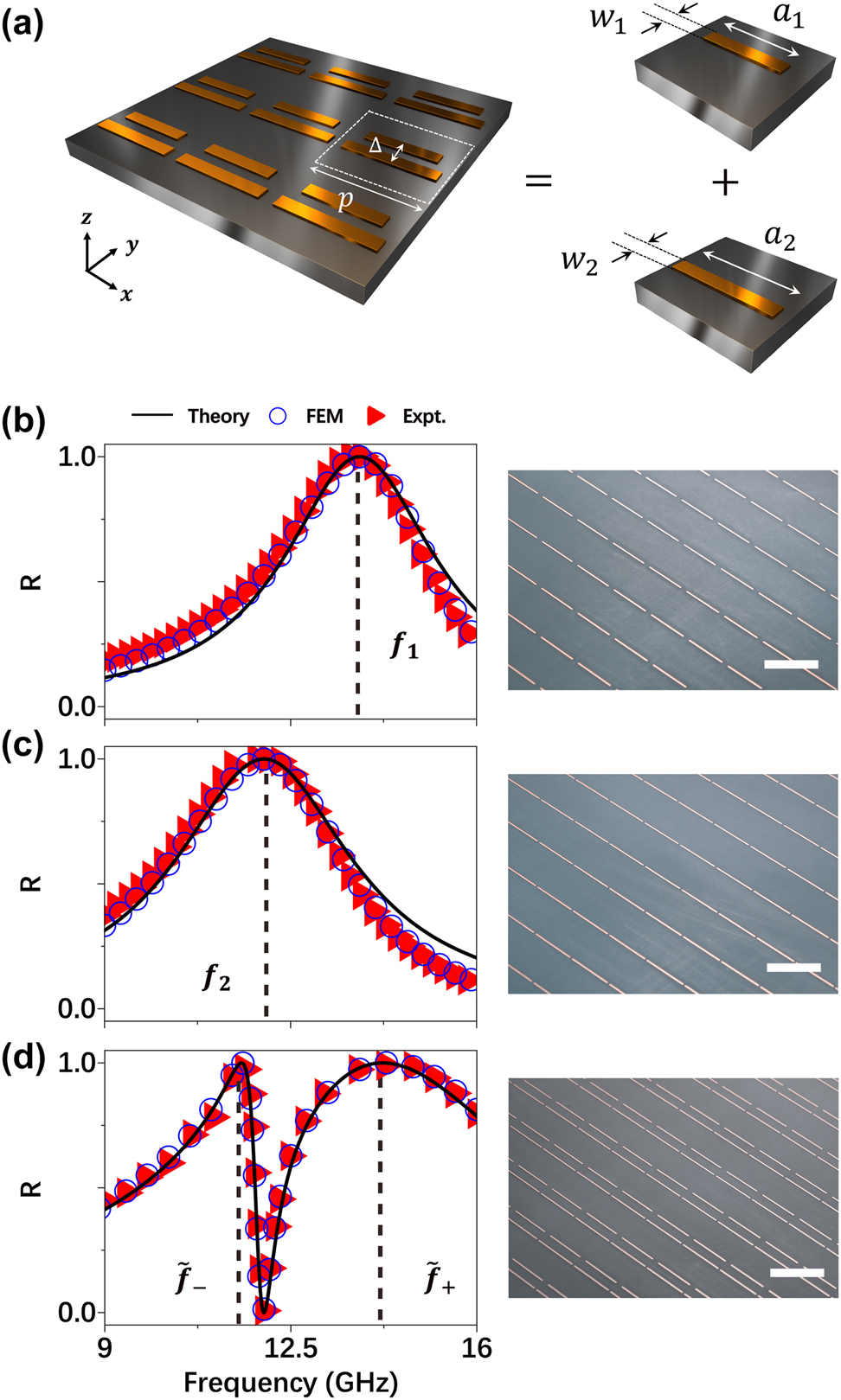
Benchmark test of our LEM theory on a realistic microwave metasurfaces. (a) Schematics of a periodic metasurface with meta-atoms composed by two coupled bar-resonators and placed at the center of its unit-cell. Geometrical parameters: p = 10 mm, Δ = 2.6 mm, a 1 = 8.5 mm, w 1 = 0.3 mm, a 2 = 9.5 mm, w 2 = 0.3 mm. And the inter-bar distance is 2.6 mm. All metallic resonators of the fabricated metasurfaces in this paper are made of copper with thickness of 35 um and placed on a dielectric substrate (with ɛ r = 2.2) with thickness of 1 mm. (b–d) Reflectance spectra of fabricated periodic metasurfaces containing different single bar-resonator (b–c) and two bar-resonators coupled together (d), obtained by experiments (triangles), FEM simulation (circles) and LEM theory (solid line). The right panel of (b–d) are the image of part of the fabricated metasurfaces with scale bar (whith line) of 10 mm.
We next use the LEM theory to analyze the reflection spectrum of a coupled system comprising two resonators separated by Δ = 2.6 mm within a unit cell (see Figure 2a). While all single-resonator-related parameters (e.g. Γ
m
, κ
mq
, d
qm
and c
qp
) are unchanged, we need to further consider the inter-resonator couplings both in the NF (i.e., t
mn
) and FF (i.e., X
mn
), which can again be unambiguously determined by the LEM theory (Eq. (5)). Substituting these parameters into Eq. (1), we compute the reflection spectra of the coupled metasurfaces, and depict them as solid line in Figure 2d. We find that the coupling between two resonators result in two “dressed” modes at frequencies
We perform both microwave experiments and FEM simulations to validate the above theoretical predictions. Three metasurface samples are fabricated according to the specified designs (see right panels in Figure 2b–d for their pictures) and their reflection spectra are measured under normal-incidence of x-polarized plane waves. We next perform FEM simulations to study the transmission spectra of these metasurfaces. As shown in Figure 2b–d, both experimental results (triangles) and FEM simulations (circles) are in excellent agreement with the LEM-calculated spectra, which unambiguously validate our LEM theory established. All reflection spectra were measured under a small incident angle (approximately 5) rather than normal incidence, in order to simplify the experimental setup, as described in Section VII of SM.
2.3 Anomalous behaviors of inter-resonator coupling at microwave frequencies
We employ the LEM theory to investigate the properties of inter-resonator couplings in such coupled microwave metasurfaces. Keeping the geometric parameters of two single-bar resonators unchanged, we design a series of metasurfaces containing two coupled bar-resonators with continuously varying inter-bar distance Δ. We then employ the LEM theory to study how the NF coupling t between two bars varies against Δ and the resulting reflection spectra of different systems. Solid lines in Figure 3a–c are the LEM-computed reflection spectra of three typical systems with Δ being 2.8 mm, 2.6 mm and 2.3 mm, respectively, which are again in perfect agreement with both numerical simulations (circles) and experimental results (triangles) of three fabricated samples (see pictures shown in the right panels of Figure 3a–c). We note that the metasurface studied in Figure 3b is identical to that in Figure 2d. Surprisingly, we notice that the frequency splitting of the two dressed modes (
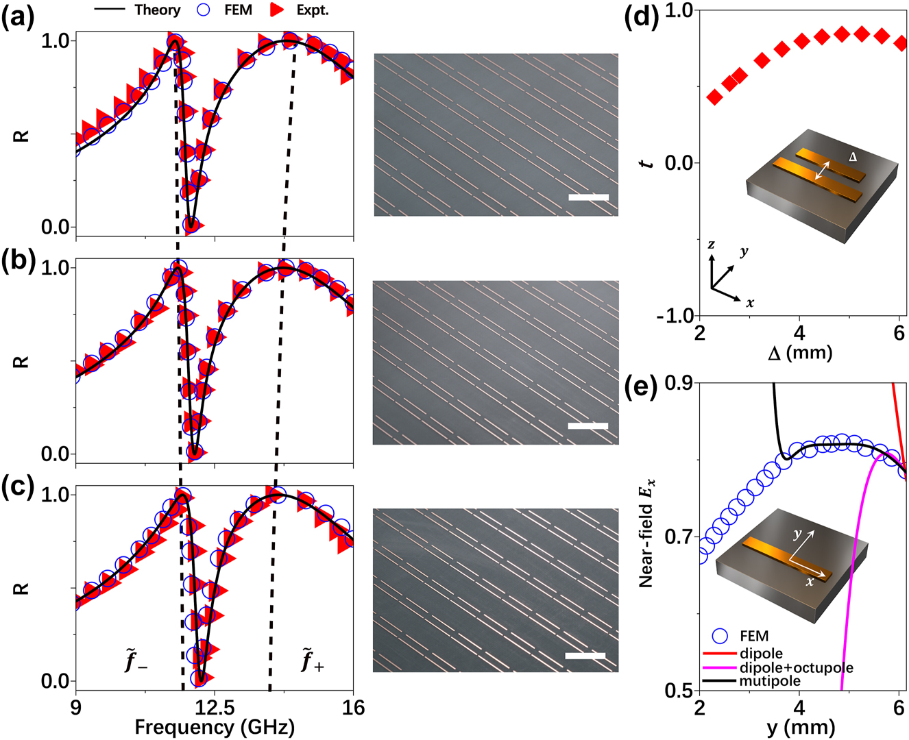
Reflectance spectra and coupling behavior of periodic metasurfaces composed by two coupled bar-resonators with different separation distances. (a–c) Reflectance spectra of fabricated periodic metasurfaces containing two bar-resonators coupled together with different separation distance Δ of 2.8 mm (a), 2.6 mm (b) and 2.3 mm (c), obtained by experiments (triangles), FEM simulation (circles) and theory (solid line), respectively. The dashed lines indicate the resonant frequencies of the “dressed” modes. The right panel of a-c are the pictures of fabricated metasurfaces with scale bar (white line) of 10 mm. (d) Theoritically calculated coupling strength t of the two coupled bar-resonators as function of the separation distance Δ. (The geometrical parameters and position of single bar-resonator and coupled bar-resonators are the same as the ones shown Figure 2a). (e) Simulated local E-field amplitude (circles) at differnt position along y-axis on the middle line of the single bar-resonantor at the working frequency of 13.8 GHz, with theoritically caltulated E-field amplitude with different multipole modles (solid lines).
To understand the underlying physics of such unusual phenomena, we perform FEM simulations to study how the field component
The unusual
2.4 Application of the theory
2.4.1 Predictive generation of BIC
As an application of our LEM theory, we apply it to tailor the optical line-shape of a microwave metasurface composed of an array of meta-atoms consisting of two bar-resonators coupled together. In particular, we illustrate how to design a metasurface exhibiting a BIC in a predictive way. As shown in Figure 3a–c, inter-resonator coupling t can significantly alter the line-shape of the coupled metasurface, through manipulating the essential properties of two “dressed” modes including their eigen frequencies and bandwidths. For the present two-mode two-port system, we find that the first equation in Eq. (1) can be explicitly written as
where
Diagonalizing the first matrix at the right-hand side of Eq. (7), we obtain
where
Here and in what follows, we have normalized all involved physical quantities (such as
We now employ Eq. (9) to analytically study how to tailor the line-shapes of coupled microwave metasurfaces. Figure 4a maps the calculated

Experimental demonstration for realizing BIC with coupled microwave metasurface. (a) Calculated the difference of radiation damping for two dressed modes
To illustrate such a line-shape evolution, we purposely choose five systems (marked as #1–5) on the solid black line across the green boundary line
We fabricate out all five samples according to the designs (see the right panel of Figure 4b for their pictures) and employ experiments and numerical simulations to verify the above predictions. Shining the metasurfaces by normally incident x-polarized plane waves, we measure their reflection spectra using the same setup as in Figures 2 and 3. As shown in Figure 4b, both experimental (triangles) and simulation (circles) results agree very well with the LEM-calculated ones (solid lines). Specifically, reflection peak of the low-frequency mode does not appear for sample #3 in both simulations and experiments, already signifying the appearance of a BIC in consistency with theoretical prediction.
We explicitly illustrate, both theoretically and experimentally, how the radiative Q factor of the low-frequency dressed mode varies against t. We depict Q values retrieved from five measured transmission spectra as circles in Figure 4c, compared with the solid line representing Q values retrieved LEM-computed transmission spectra for a series of coupled metasurfaces with varying t. Experimentally measured Q factors are in excellent agreement with theoretical predictions, both showing that Q diverges at a specific point indicating the emergence of a BIC. To understand the physics behind such a fascinating effect, we employ FEM to simulate the Re(Ex) distributions of waves radiated from three systems, i.e., two metasurfaces containing periodic arrays of two single-type bar resonators and system #3 containing the coupled meta-atoms, under excitations of incident waves at the BIC working frequency. Three computed Re(Ex) patterns are compared in Figure S5 in SM. Clearly, while two single resonators still radiate well to the far-field, the coupled meta-atom does not. In fact, wave-function of the “dressed” mode in the coupled system is a linear combination of two original modes [38],
It is worth mentioning that our extended LEM method can not only be used to study the near-field coupling effects induced by lateral shifts between meta-atoms, but also to understand the influence of near-field coupling and far-field radiation behavior caused by vertical shifts, as demonstrated in Ref. [17] in the optical regime. In addition, our LEM theory is applicable under oblique incidence (see more details in Section VIII in SM), provided that the subwavelength characteristics of the metasurfaces are maintained across different incident angles.
2.4.2 Tailoring the optical line-shape
Apart from the predictive generation of a BIC, we further illustrate how to employ our theory to freely tailor the optical line-shape of the coupled system. As shown in the phase diagram Figure 4a, radiation-damping difference
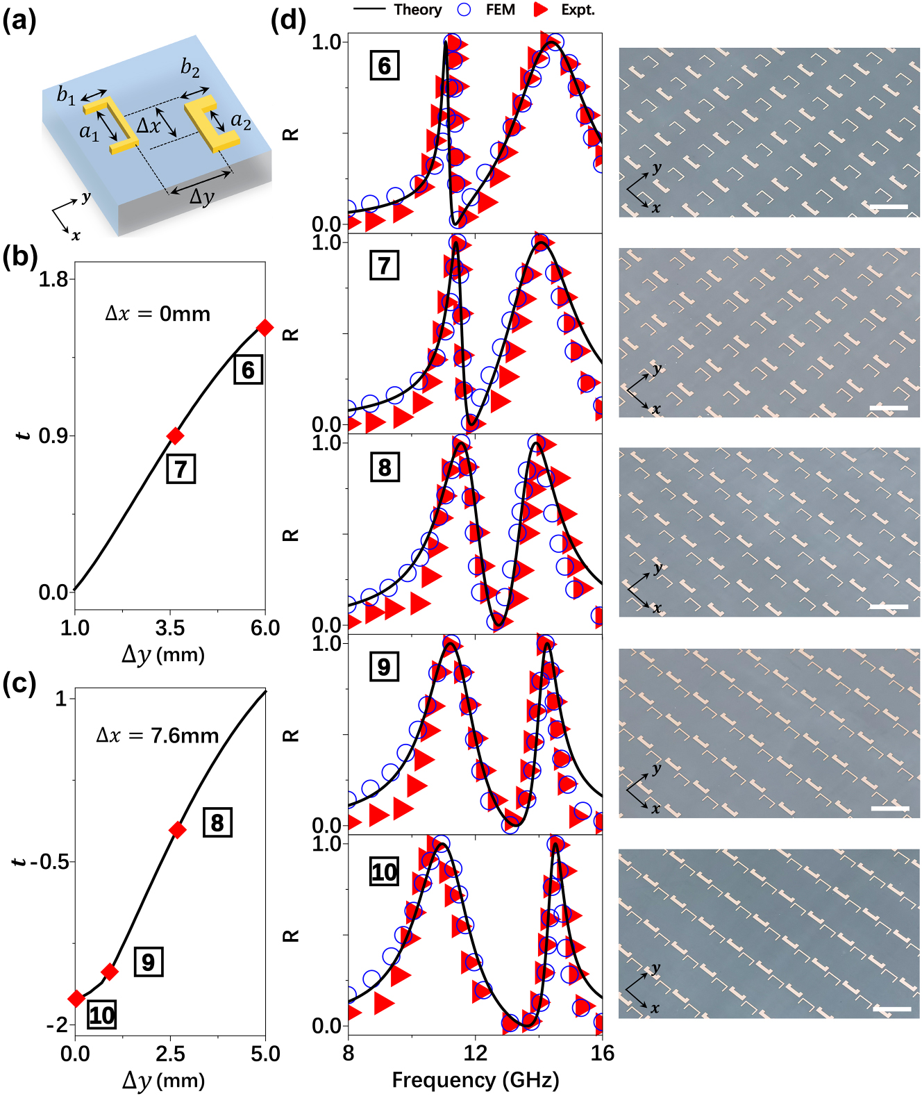
Experimental demonstration for line-shape tailoring: (a) schematics of a unitcell in a periodic metasurface composed by two coupled resonators. Geometrical parameters: a 1 = 5.08 mm, b 1 = 2.93 mm, a 2 = 3.5 mm, b 2 = 2.15 mm and their linewidths are 0.4 mm and 1.3 mm, respectively with period is 15 mm. (b–c) The relationship between the relative position variation of the resonators at points #6–#10 and the near-field coupling strength t. (d) Optical line-shapes (reflection spectra) of the metasurfaces containing two-resonators coupled differently with different Δ corresponding to the 5 points labelled as #6–10 obtained by our theory (solid lines), FEM simulations (circles), experiments (triangles). Insets: pictures of fabricated samples with the scale bars (white lines) is 15 mm, other parameters can be found in Table S2 in SM.
We now experimentally verify the above predictions. We first design two new resonators with appropriate
3 Conclusions
In summary, we have extended our previously established LEM theory to low-frequency regimes where metals exhibit infinite permittivity, by replacing all volume integrations involving E and j by surface integrations on the resonator surfaces. After validating our extended LEM theory by both simulations and experiments, we revealed the underlying physics of the abnormal behaviors of near-field couplings at microwave frequencies, and applied the theory to guide designing coupled metasurfaces with tailored line-shapes. Specifically, we illustrate how to design a microwave metasurface exhibiting a BIC, and how to design coupled metasurfaces with freely tailored optical line-shapes. All theoretical predictions are verified by microwave experiments and full-wave simulations. Our study provides a powerful tool to guide designing functional microwave meta-devices for various applications, such as smart radar systems requiring real-time reconfigurable filters for microwave communications, lab-on-chip biosensors leveraging BIC-engineered linewidth compression for molecular fingerprinting.
Funding source: China Postdoctoral Science Foundation
Award Identifier / Grant number: 2021TQ0077
Funding source: National Natural Science Foundation of China
Award Identifier / Grant number: No.12474306, No. 12221004, and No. 62192771
Funding source: Natural Science Foundation of Shanghai Municipality
Award Identifier / Grant number: 23dz2260100, 23xtcx00400 and 22JC1400200
Funding source: National Key Research and Development Program of China
Award Identifier / Grant number: No. 2022YFA1404700
-
Research funding: This work was funded by National Key Research and Development Program of China (No. 2022YFA1404700), National Natural Science Foundation of China (No. 12474306, No. 12221004, and No. 62192771), Natural Science Foundation of Shanghai (23dz2260100, 23xtcx00400 and 22JC1400200), and China Postdoctoral Science Foundation (2021TQ0077).
-
Author contributions: YX, YS and HZ contributed equally to this work. YX did the theoretical calculations, carried out simulations, designed the samples and conducted part of the measurements. YS built the experimental setup and conducted part of measurements. HZ and YW conducted part of the theoretical analysis. QH and ZW provided technical supports for experiments and measurements. LZ conceived the idea and supervised the project. All authors have accepted responsibility for the entire content of this manuscript and consented to its submission to the journal, reviewed all the results and approved the final version of the manuscript.
-
Conflict of interest: Authors state no conflicts of interest.
-
Data availability: Data sharing is not applicable to this article as no datasets were generated or analyzed during the current study.
References
[1] N. Yu and F. Capasso, “Flat optics with designer metasurfaces,” Nat. Mater., vol. 13, no. 2, pp. 139–150, 2014. https://doi.org/10.1038/nmat3839.Suche in Google Scholar PubMed
[2] S. Sun, Q. He, J. Hao, S. Xiao, and L. Zhou, “Electromagnetic metasurfaces: physics and applications,” Adv. Opt. Photonics, vol. 11, no. 2, pp. 380–479, 2019. https://doi.org/10.1364/aop.11.000380.Suche in Google Scholar
[3] H. H. Hsiao, C. H. Chu, and D. P. Tsai, “Fundamentals and applications of metasurfaces,” Small Methods, vol. 1, no. 4, p. 1600064, 2017. https://doi.org/10.1002/smtd.201600064.Suche in Google Scholar
[4] N. Yu, et al.., “Light propagation with phase discontinuities: generalized laws of reflection and refraction,” Science, vol. 334, no. 6054, pp. 333–337, 2011. https://doi.org/10.1126/science.1210713.Suche in Google Scholar PubMed
[5] X. Ni, N. K. Emani, A. V. Kildishev, A. Boltasseva, and V. M. Shalaev, “Broadband light bending with plasmonic nanoantennas,” Science, vol. 335, no. 6067, p. 427, 2012. https://doi.org/10.1126/science.1214686.Suche in Google Scholar PubMed
[6] S. Sun, Q. He, S. Xiao, Q. Xu, X. Li, and L. Zhou, “Gradient-index meta-surfaces as a bridge linking propagating waves and surface waves,” Nat. Mater., vol. 11, no. 5, pp. 426–431, 2012. https://doi.org/10.1038/nmat3292.Suche in Google Scholar PubMed
[7] B. Wang, et al.., “Visible-frequency dielectric metasurfaces for multiwavelength achromatic and highly dispersive holograms,” Nano Lett., vol. 16, no. 8, pp. 5235–5240, 2016. https://doi.org/10.1021/acs.nanolett.6b02326.Suche in Google Scholar PubMed
[8] J. C. Zhang, et al.., “Programmable optical meta-holograms,” Nanophotonics, vol. 13, no. 8, pp. 1201–1217, 2024. https://doi.org/10.1515/nanoph-2023-0544.Suche in Google Scholar PubMed PubMed Central
[9] G. Zheng, H. Mühlenbernd, M. Kenney, G. Li, T. Zentgraf, and S. Zhang, “Metasurface holograms reaching 80% efficiency,” Nat. Nanotechnol., vol. 10, no. 4, pp. 308–312, 2015. https://doi.org/10.1038/nnano.2015.2.Suche in Google Scholar PubMed
[10] X. Liu, et al.., “Underwater binocular meta-lens,” ACS Photonics, vol. 10, no. 7, pp. 2382–2389, 2023. https://doi.org/10.1021/acsphotonics.2c01667.Suche in Google Scholar
[11] S. Wang, et al.., “A broadband achromatic metalens in the visible,” Nat. Nanotechnol., vol. 13, no. 3, pp. 227–232, 2018. https://doi.org/10.1038/s41565-017-0052-4.Suche in Google Scholar PubMed
[12] M. Khorasaninejad, W. T. Chen, R. C. Devlin, J. Oh, A. Y. Zhu, and F. Capasso, “Metalenses at visible wavelengths: diffraction-limited focusing and subwavelength resolution imaging,” Science, vol. 352, no. 6290, pp. 1190–1194, 2016. https://doi.org/10.1126/science.aaf6644.Suche in Google Scholar PubMed
[13] Z. Wang, et al.., “Efficient generation of vectorial terahertz beams using surface-wave excited metasurfaces,” Opto-Electron. Sci., vol. 4, no. 1, p. 240024, 2025. https://doi.org/10.29026/oes.2025.240024.Suche in Google Scholar
[14] Y. Chen, et al.., “Efficient meta-couplers squeezing propagating light into on-chip subwavelength devices in a controllable way,” Nano Lett., vol. 23, no. 8, pp. 3326–3333, 2023. https://doi.org/10.1021/acs.nanolett.3c00310.Suche in Google Scholar PubMed
[15] Y. Bao, et al.., “Coherent pixel design of metasurfaces for multidimensional optical control of multiple printing-image switching and encoding,” Adv. Funct. Mater., vol. 28, no. 51, p. 1805306, 2018. https://doi.org/10.1002/adfm.201805306.Suche in Google Scholar
[16] Y. Zhou, T. Liu, C. Dai, D. Wang, and L. Zhou, “Functionality multiplexing in high-efficiency metasurfaces based on coherent wave interferences,” Opto-Electron. Adv., vol. 11, no. 7, p. 240086, 2024. https://doi.org/10.29026/oea.2024.240086.Suche in Google Scholar
[17] X. Zheng, J. Lin, Z. Wang, H. Zhou, Q. He, and L. Zhou, “Manipulating light transmission and absorption via an achromatic reflectionless metasurface,” PhotoniX, vol. 4, no. 1, p. 3, 2023. https://doi.org/10.1186/s43074-022-00078-w.Suche in Google Scholar
[18] C. Dai, T. Liu, D. Wang, and L. Zhou, “Multiplexing near-and far-field functionalities with high-efficiency bi-channel metasurfaces,” PhotoniX, vol. 5, no. 1, p. 11, 2024. https://doi.org/10.1186/s43074-024-00128-5.Suche in Google Scholar
[19] H. Arianfard, J. Wu, S. Juodkazis, and D. J. Moss, “Optical analogs of Rabi splitting in integrated waveguide-coupled resonators,” Adv. Phys. Res., vol. 2, no. 9, p. 2200123, 2023. https://doi.org/10.1002/apxr.202200123.Suche in Google Scholar
[20] K. Santhosh, O. Bitton, L. Chuntonov, and G. Haran, “Vacuum Rabi splitting in a plasmonic cavity at the single quantum emitter limit,” Nat. Commun., vol. 7, no. 1, p. ncomms11823, 2016. https://doi.org/10.1038/ncomms11823.Suche in Google Scholar PubMed PubMed Central
[21] S. Rudin and T. Reinecke, “Oscillator model for vacuum Rabi splitting in microcavities,” Phys. Rev. B, vol. 59, no. 15, p. 10227, 1999. https://doi.org/10.1103/physrevb.59.10227.Suche in Google Scholar
[22] B. Luk’Yanchuk, et al.., “The Fano resonance in plasmonic nanostructures and metamaterials,” Nat. Mater., vol. 9, no. 9, pp. 707–715, 2010.10.1038/nmat2810Suche in Google Scholar PubMed
[23] M. F. Limonov, M. V. Rybin, A. N. Poddubny, and Y. S. Kivshar, “Fano resonances in photonics,” Nat. Photonics, vol. 11, no. 9, pp. 543–554, 2017. https://doi.org/10.1038/nphoton.2017.142.Suche in Google Scholar
[24] A. E. Miroshnichenko, S. Flach, and Y. S. Kivshar, “Fano resonances in nanoscale structures,” Rev. Mod. Phys., vol. 82, no. 3, pp. 2257–2298, 2010. https://doi.org/10.1103/revmodphys.82.2257.Suche in Google Scholar
[25] M. Kang, T. Liu, C. Chan, and M. Xiao, “Applications of bound states in the continuum in photonics,” Nat. Rev. Phys., vol. 5, no. 11, pp. 659–678, 2023. https://doi.org/10.1038/s42254-023-00642-8.Suche in Google Scholar
[26] C. W. Hsu, B. Zhen, A. D. Stone, J. D. Joannopoulos, and M. Soljačić, “Bound states in the continuum,” Nat. Rev. Mater., vol. 1, no. 9, pp. 1–13, 2016. https://doi.org/10.1038/natrevmats.2016.48.Suche in Google Scholar
[27] D. Marinica, A. Borisov, and S. Shabanov, “Bound states in the continuum in photonics,” Phys. Rev. Lett., vol. 100, no. 18, p. 183902, 2008. https://doi.org/10.1103/physrevlett.100.183902.Suche in Google Scholar
[28] C. Zhou, et al.., “Bound states in the continuum in asymmetric dielectric metasurfaces,” Laser Photonics Rev., vol. 17, no. 3, p. 2200564, 2023. https://doi.org/10.1002/lpor.202200564.Suche in Google Scholar
[29] Z. Liu, et al.., “Phase interrogation sensor based on all-dielectric BIC metasurface,” Nano Lett., vol. 23, no. 22, pp. 10441–10448, 2023. https://doi.org/10.1021/acs.nanolett.3c03089.Suche in Google Scholar PubMed
[30] S. B. Saadatmand, V. Ahmadi, and S. M. Hamidi, “Quasi-BIC based all-dielectric metasurfaces for ultra-sensitive refractive index and temperature sensing,” Sci. Rep., vol. 13, no. 1, p. 20625, 2023. https://doi.org/10.1038/s41598-023-48051-2.Suche in Google Scholar PubMed PubMed Central
[31] J. Wang, L. Shi, and J. Zi, “Spin Hall effect of light via momentum-space topological vortices around bound states in the continuum,” Phys. Rev. Lett., vol. 129, no. 23, p. 236101, 2022. https://doi.org/10.1103/physrevlett.129.236101.Suche in Google Scholar PubMed
[32] D. C. Wang, R. Tang, Z. Feng, S. Sun, S. Xiao, and W. Tan, “Symmetry-assisted spectral line shapes manipulation in dielectric double-fano metasurfaces,” Adv. Opt. Mater., vol. 9, no. 4, p. 2001874, 2021. https://doi.org/10.1002/adom.202001874.Suche in Google Scholar
[33] S. Weitemeyer, M. Husnik, and M. Wegener, “Observation of unusual absorption and scattering cross-section line shapes of individual optical double-wire antennas,” Appl. Phys. Lett., vol. 104, no. 3, 2014, https://doi.org/10.1063/1.4863226.Suche in Google Scholar
[34] S. Xia, et al.., “Unconventional flatband line states in photonic Lieb lattices,” Phys. Rev. Lett., vol. 121, no. 26, p. 263902, 2018. https://doi.org/10.1103/physrevlett.121.263902.Suche in Google Scholar
[35] S. Fan, W. Suh, and J. D. Joannopoulos, “Temporal coupled-mode theory for the Fano resonance in optical resonators,” J. Opt. Soc. Am. A, vol. 20, no. 3, pp. 569–572, 2003. https://doi.org/10.1364/josaa.20.000569.Suche in Google Scholar PubMed
[36] W. Suh, Z. Wang, and S. Fan, “Temporal coupled-mode theory and the presence of non-orthogonal modes in lossless multimode cavities,” IEEE J. Quantum Electron., vol. 40, no. 10, pp. 1511–1518, 2004. https://doi.org/10.1109/jqe.2004.834773.Suche in Google Scholar
[37] M. Zhou, S. W. Belling, H. Chen, and Z. Yu, “Coupled mode theory for metasurface design,” Metamater. Metadev. Metasyst., vol. 11080, pp. 127–133, 2019.10.1117/12.2528909Suche in Google Scholar
[38] Z. Fan, M. R. Shcherbakov, M. Allen, J. Allen, B. Wenner, and G. Shvets, “Perfect diffraction with multiresonant bianisotropic metagratings,” ACS Photonics, vol. 5, no. 11, pp. 4303–4311, 2018. https://doi.org/10.1021/acsphotonics.8b00434.Suche in Google Scholar
[39] J. Lin, et al.., “Tailoring the lineshapes of coupled plasmonic systems based on a theory derived from first principles,” Light Sci. Appl., vol. 9, p. 158, 2020. https://doi.org/10.1038/s41377-020-00386-5.Suche in Google Scholar PubMed PubMed Central
[40] X. Zhang, et al.., “Controlling angular dispersions in optical metasurfaces,” Light Sci. Appl., vol. 9, p. 76, 2020. https://doi.org/10.1038/s41377-020-0313-0.Suche in Google Scholar PubMed PubMed Central
Supplementary Material
This article contains supplementary material (https://doi.org/10.1515/nanoph-2025-0113).
© 2025 the author(s), published by De Gruyter, Berlin/Boston
This work is licensed under the Creative Commons Attribution 4.0 International License.