Dispersive surface-response formalism to address nonlocality in extreme plasmonic field confinement
-
Antton Babaze

 ,
Tomáš Neuman
,
Ruben Esteban
,
Javier Aizpurua
and
Andrei G. Borisov
,
Tomáš Neuman
,
Ruben Esteban
,
Javier Aizpurua
and
Andrei G. Borisov

Abstract
The surface-response formalism (SRF), where quantum surface-response corrections are incorporated into the classical electromagnetic theory via the Feibelman parameters, serves to address quantum effects in the optical response of metallic nanostructures. So far, the Feibelman parameters have been typically obtained from many-body calculations performed in the long-wavelength approximation, which neglects the nonlocality of the optical response in the direction parallel to the metal–dielectric interface, thus preventing to address the optical response of systems with extreme field confinement. To improve this approach, we introduce a dispersive SRF based on a general Feibelman parameter d ⊥(ω, k ‖), which is a function of both the excitation frequency, ω, and the wavenumber parallel to the planar metal surface, k ‖. An explicit comparison with time-dependent density functional theory (TDDFT) results shows that the dispersive SRF correctly describes the plasmonic response of planar and nonplanar systems featuring extreme field confinement. This work thus significantly extends the applicability range of the SRF, contributing to the development of computationally efficient semiclassical descriptions of light–matter interaction that capture quantum effects.
1 Introduction
The excitation of plasmon resonances in metallic nanostructures has attracted great interest owing to the capability of nanoscale plasmonic systems to enhance and squeeze incident electromagnetic fields at subwavelength regions. Plasmon resonances have been widely used in a variety of spectroscopy and microscopy techniques such as surface-enhanced Raman spectroscopy [1], surface-enhanced fluorescence [2], [3], [4], or single-molecule imaging [5, 6], and enable promising applications in biomedicine [7], [8], [9], energy storage [10], [11], [12], and nonlinear optics [13, 14], among others. Miniaturization of plasmonic devices pushes light–matter interaction to the limit, reaching situations where quantum many-body phenomena can influence the optical properties of a system [15– 22]. In these extreme situations, classical descriptions based on local dielectric functions of materials characterized by abrupt interfaces are no longer valid [23, 24]. Thus, theoretical approaches incorporating nonlocality [25– 30], realistic electron density distribution at the interfaces [31– 34], and electron tunneling [35, 36] are required to describe the optical properties of plasmonic structures with very small characteristic dimensions. In this context, time-dependent density functional theory (TDDFT) is often used because it accounts for the quantum nature of the electron dynamics from first principles [37– 41]. However, because of its computational cost [42, 43], TDDFT is limited to addressing systems with a relatively low number of electrons in the relevant dimension(s) of the nanostructure (typically a few-nanometers structures). As a consequence, computationally less-demanding semiclassical approaches have been developed to capture quantum effects within the framework of classical electrodynamics [33, 44– 55].
Among the semiclassical approaches, the surface-response formalism (SRF) [23, 56], [57], [58], [59] has prompted great interest in the nanophotonics community over the last few years. The SRF is based on the theoretical framework proposed by Peter Feibelman in the eighties [60] to describe the interaction of electromagnetic radiation with planar metal surfaces. This formalism introduces quantum surface-response corrections into the classical Maxwell’s theory [61] through the so-called Feibelman parameters. As a consequence, quantum effects such as surface-enabled Landau damping [62], [63], [64], spill-out of the induced electron density [34, 51, 54], and nonlocal dynamical screening [27, 28, 57, 65] are accounted for. The Feibelman parameters, commonly denoted as d ⊥ and d ‖, are complex-valued functions characterizing the dynamically induced charges (d ⊥) and the parallel-to-the-surface component of the induced currents (d ‖) at the metal–dielectric interface [32].
In the literature, the practical implementation of the SRF within the Feibelman theory typically involves two approximations. First, d ‖ is assumed to be zero, which is a reasonable approach given that d ‖ strictly vanishes for charge-neutral planar interfaces [32, 56, 66]. Second, the nonlocality of the optical response in the direction parallel to the metal–dielectric interface is neglected. Within this long-wavelength approximation, it is considered that the characteristic wavenumber k ‖ parallel to the metal surface is negligible, so that the Feibelman parameter d ⊥(ω) is exclusively a function of the excitation frequency, ω. Considering the long-wavelength limit with k ‖ = 0 reduces the computational effort in obtaining d ⊥(ω) from quantum calculations, and simplifies the implementation of the SRF in existing numerical tools that solve Maxwell’s equations in nanophotonics, as employed in a number of recent studies [59, 67–74]. In what follows, we refer to d ⊥(ω) as the nondispersive Feibelman parameter.
Using the nondispersive Feibelman parameter is reasonable when the nonlocality of the optical response in the direction perpendicular to the metal surface dominates, i.e., when the characteristic length scale of the optical field variation along the surface is relatively large, 2π/k ‖ ≫ λ F , where λ F is the Fermi wavelength of the metal. This is the case of e.g. typical individual nanoparticles subjected to plane-wave illumination. However, for localized probes in proximity of metal nanoparticle surfaces, where high-order plasmonic modes can be excited, the long-wavelength approximation to d ⊥(ω) is compromised [75]. Indeed, in such situations, multipolar plasmon modes characterized by localized surface charges that rapidly vary along the nanoparticle surface are involved. This is analogous to exciting surface plasmons with large transverse wavenumber k ‖ at planar metal–dielectric interfaces, and therefore requires going beyond the long-wavelength limit of d ⊥.
In this work, we demonstrate that considering the nonlocality of the optical response in the direction parallel to the metal surface significantly improves the performance of the SRF. While earlier theory addresses the role of nonlocality by introducing an ad hoc dipole layer [58], we base our approach on the implementation of a dispersive Feibelman parameter d ⊥(ω, k ‖) that is a function of ω and k ‖, providing a direct connection of the theory to the microscopic quantum aspects of screening. The numerical values of this parameter are obtained from linear-response frequency-domain TDDFT calculations using a planar free-electron metal slab. We then show that the dispersive SRF based on the same set of d ⊥(ω, k ‖) can be used to describe the plasmon modes and optical response not only for planar surfaces, but also for nonplanar geometries. In particular, the method proposed in this work is relevant for situations where plasmon resonances with large transverse momenta (small plasmon wavelength) are excited. We test the validity of the dispersive SRF by using quantum many-body TDDFT simulations as a reference for a planar metal surface (Figure 1a) as well as for canonical plasmonic nanostructures such as cylindrical metallic nanowires, small spherical metal nanoparticles, and plasmonic gaps as exemplified by a spherical dimer (Figure 1b). In all the systems studied, the dispersive SRF reproduces the TDDFT results, demonstrating its validity to capture the effects linked to nonlocality of dynamical screening along the metal surface. The theoretical framework proposed here provides significant conceptual advances toward the implementation of efficient semiclassical approaches that adequately account for quantum effects in the optical response of plasmonic systems.
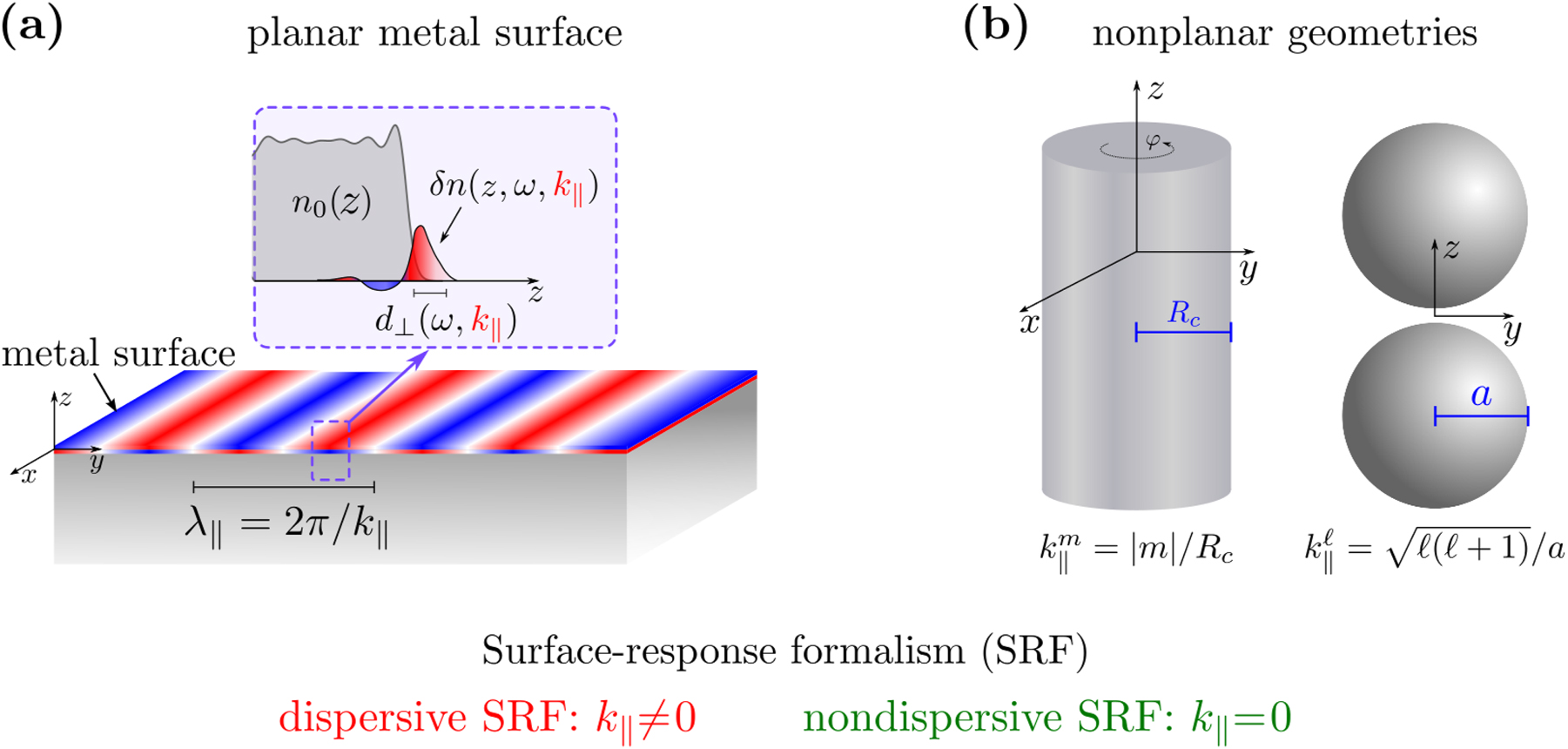
Dispersive surface-response formalism for plasmonic systems. (a) Sketch of the dispersive surface-response formalism (SRF) employed in this work. The real part of the dispersive Feibelman parameter d
⊥(ω, k
‖) accounts for the position of the centroid of the induced electron density δn(z, ω, k
‖) relative to the geometrical metal surface, and the imaginary part is related to surface-enabled Landau damping. The dispersive Feibelman parameter d
⊥(ω, k
‖) is a function of the excitation frequency, ω, and the wavenumber parallel to the planar metal surface, k
‖ = 2π/λ
‖ (with λ
‖ the wavelength of the nonretarded surface plasmon). The nondispersive SRF assumes that k
‖ = 0 (λ
‖ → ∞), so that d
⊥ is a function of ω exclusively. n
0(z) represents the equilibrium electron density. (b) Sketch of nonplanar structures considered in this work. Left: cylindrical metallic nanowire with radius R
c
, infinite along the z-axis, with φ the azimuth angle. The system possesses rotational and translational symmetry with respect to the z-axis. The equivalence between k
‖ and |m|/R
c
is used to implement the dispersive SRF in the cylindrical nanowire,
2 Methodology
To obtain the dispersive Feibelman parameter, d
⊥(ω, k
‖), we employ linear-response frequency-domain TDDFT calculations for a planar metal slab. The adiabatic local-density approximation (ALDA) with the exchange–correlation potential given by Gunnarsson and Lunqvist [76] is used. The metal slab is infinite along the (x, y)-plane and has a finite thickness L in the z-direction. The metal surface is located in the (x, y, z = 0) plane, with vacuum at z > 0 (see Figure 1a). The electronic structure of the slab is described within the jellium model of free-electron metals [77–81] using a Wigner–Seitz radius r
s
= 4 a
0 that corresponds to sodium (a
0 = 0.0529 nm is the Bohr radius). The bulk plasma frequency is ω
p
= 5.89 eV, and the nonretarded surface plasmon frequency for k
‖ = 0 is
Since the nonlocality of the metal response in the direction parallel to the surface is important in geometries confining fields at typical length scales comparable to that of the Fermi wavelength of electrons [58, 75] (i.e., within the nm range), we use the nonretarded approximation within the linear-response theory. The optical response of the metal slab to a time-dependent external potential
Within the many-body formalism, δn(z, ω, k ‖) is given by
where
which exponentially decays within the metal (z < 0). Note that, up to a multiplying factor, Eq. (2) represents the asymptotic behavior of the potential created by any charge distribution located in vacuum far from the surface, since the plane-wave decomposition of such potential can be obtained from the Green’s function G(r − r′) corresponding to the potential of a point charge located at r′:
In this respect, within the linear-response regime the induced electron density δn(z, ω, k ‖) given by Eq. (1) is independent of the specific form of the external potential that excites the system.
The dispersive Feibelman parameter d ⊥(ω, k ‖) obtained from
is therefore a characteristic of the surface response inherent to the specific metal and the surrounding material [32]. In contrast to the nondispersive parameter [59, 67, 70], [71], [72], [73], the dispersive d ⊥(ω, k ‖) introduced in Eq. (4) depends on the wavenumber k ‖ parallel to the surface, and thus explicitly accounts for the nonlocality of the many-body response and screening in this direction. Other definitions different from Eq. (4) that express the Feibelman parameter in terms of the electromagnetic fields and nonlocal dielectric functions have also been used. A discussion on the equivalence between Eq. (4) and other definitions can be found in refs. [32, 60, 83].
As follows from Eq. (2), the z-extension of the external potential within the metal slab increases with decreasing k
‖. In our calculations (where k
‖ ≠ 0), we use a slab with thickness L = 870 a
0
3 Results and discussion
3.1 Dispersive Feibelman parameter
Figure 2 shows the real part
![Figure 2:
Dispersive Feibelman parameter. (a) Real part of the dispersive Feibelman parameter,
Re
d
⊥
(
ω
,
k
‖
)
$\text{Re}\left\{{d}_{\perp }(\omega ,{k}_{\Vert })\right\}$
, calculated here within the linear-response frequency-domain TDDFT as a function of frequency ω, for selected values of k
‖ as indicated in panel b. We also show the parameter
Re
d
⊥
(
ω
)
$\text{Re}\left\{{d}_{\perp }(\omega )\right\}$
obtained in ref. [67] by Christensen et al. under the long-wavelength approximation (dashed green line). (b) Same as in (a) but for the imaginary part of the dispersive Feibelman parameter,
Im
d
⊥
(
ω
,
k
‖
)
$\text{Im}\left\{{d}_{\perp }(\omega ,{k}_{\Vert })\right\}$
.](/document/doi/10.1515/nanoph-2023-0178/asset/graphic/j_nanoph-2023-0178_fig_002.jpg)
Dispersive Feibelman parameter. (a) Real part of the dispersive Feibelman parameter,
For small k
‖, the TDDFT results in Figure 2 are consistent with earlier findings for k
‖ = 0 [67], with d
⊥(ω, k
‖) featuring a complex Lorentzian-like resonance at ω ∼ 4.6 eV. This resonance is associated with the excitation of the Bennett plasmon at ω ∼ 0.8ω
p
[42, 85, 88]. With increasing k
‖, the Bennett plasmon resonance broadens, blueshifts, and gradually disappears.
Importantly, in the frequency range ω ∼ 2 − 4.5 eV relevant for plasmon excitations in different structures (see below), the following trends can be observed with increasing k ‖:
In general, the results in Figure 2 demonstrate a strong dependence of the dispersive Feibelman parameter d ⊥(ω, k ‖) on k ‖ due to nonlocal dynamical screening. Thus, one can expect that the dispersive and nondispersive SRF yield very different results in situations that involve a rapid variation of plasmon-induced charges along the metal–vacuum interface. In the following sections, we analyze the limitations of the nondispersive SRF and illustrate the good performance of the dispersive SRF using the example of canonical plasmonic nanostructures described semiclassically within the SRF and quantum mechanically within TDDFT. Our results show that the dispersive SRF correctly captures quantum surface effects within a computationally efficient semiclassical framework.
3.2 Validation of the dispersive SRF
3.2.1 Nonlocal dynamical screening of a planar metal surface
As a first application of the SRF, we consider the plasmon propagating at the interface between a planar metal surface and vacuum. The surface plasmon frequency dispersion ω
s
(k
‖) with parallel wavenumber can be obtained within TDDFT from the surface loss function Im
where the induced electron density δn(z, ω, k ‖) is obtained within TDDFT considering the slab geometry introduced in the previous section.
Figure 3a shows the frequency dependence of the surface loss function, Im
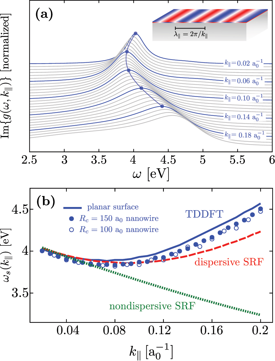
Surface plasmon dispersion. (a) Surface loss function, Im
The frequency dispersion ω
s
(k
‖) featured by the plasmon resonances in Figure 3a is intimately related to the k
‖-dependence of the position of the centroid of the induced electron density (given by Re{d
⊥(ω, k
‖)}). Indeed, for low k
‖ the induced electron density is shifted outward from the geometrical metal surface (Re{d
⊥(ω, k
‖)} > 0 in Figure 2a), i.e., toward the region of lower electron density, which produces the redshift of ω
s
(k
‖) with respect to
We continue the quantitative analysis of the plasmon dispersion in Figure 3b, where we show the resonant plasmon frequency ω s (k ‖) obtained from TDDFT calculations (blue solid line) and compare it with dispersive (red dashed line) and nondispersive (green dotted line) SRF results. To find the ω s (k ‖) dispersion using the SRF based on the Feibelman parameters, we describe the dielectric function of the metal with a Drude model, and self-consistently solve the following transcendental equation [32, 60, 65, 84, 96], [97], [98],
where
Figure 3b shows that the dispersive SRF and TDDFT results are in good agreement within the broad range of k
‖ values considered here. The dispersive SRF reproduces the redshift followed by blueshift of ω
s
(k
‖) with increasing k
‖ as predicted by TDDFT. For high k
‖ values, the quantitative agreement between the two sets of results worsens. This may be attributed to the short lifetime of plasmon modes at high k
‖. The resonant structures in the surface loss function become broad and asymmetric so that the resonant frequencies are ill defined. Additionally, higher-order terms of the induced electron density near the surface beyond the leading dipolar contribution accounted for with d
⊥(ω, k
‖) may gain in importance in such situations. In sheer contrast, the nondispersive SRF fails to describe the entire ω
s
(k
‖) dependence, since it predicts a continuous redshift of ω
s
(k
‖) with increasing k
‖. Therefore, the nondispersive SRF is only accurate for small values of
3.2.2 Localized multipolar plasmon resonances in a cylindrical nanowire
We study next the applicability of the dispersive SRF to address nonlocal effects in the optical response and plasmon resonances of nonplanar plasmonic nanostructures used in a variety of applications in nanophotonics. To this end, we first consider localized multipolar plasmons (LMP) sustained by cylindrical metallic nanowires of radii R c = 75 − 150 a 0 (≈4 − 8 nm), infinite along the z-axis (see Figure 1b). The nanowire is described within the same jellium model as that used for the metal slab. The reference quantum calculations are performed using real-time ALDA-TDDFT as implemented in prior works [27, 28, 99], [100], [101], [102] (see Section S2 of Supplementary Material for further details). The excitation of LMPs evolving in the (x, y)-plane determines the optical response of the nanowire for an incident electromagnetic wave polarized such that its electric field is perpendicular to the nanowire z-axis. The system is translationally invariant along the z-axis, and under the illumination conditions considered here, the wavevector describing the plasmon propagation along the nanowire is k z = 0 (see Supplementary Material). Consistent with the symmetry, the LMPs can be characterized by their multipole order m related to the eimφ dependence on the azimuth angle φ of the potentials, electric near fields, and induced charges.
To analyze the spectral properties of the LMPs of order m, we show in Figure 4a the TDDFT results of the imaginary part of the multipolar polarizability α m (ω) per unit length along the z-axis of a cylindrical nanowire of radius R c = 150 a 0 (see Section S4 in Supplementary Material). Results are presented as a function of frequency for different values of m ranging from m = 1 (top) to m = 30 (bottom). The resonances in Im{α m (ω)} are associated with the excitation of the corresponding LMP of order m. Interestingly, their general behavior with m is similar to that of the propagating surface plasmon with k ‖ (see Figure 3a). Indeed, the resonant frequency ω m first redshifts starting with m = 1, and, after reaching a minimum value at m ≈ 10, it continuously blueshifts. Moreover, similarly to the situation of the planar surface, the width of the LMP resonances increases with increasing m because of the enhancement of Landau damping.
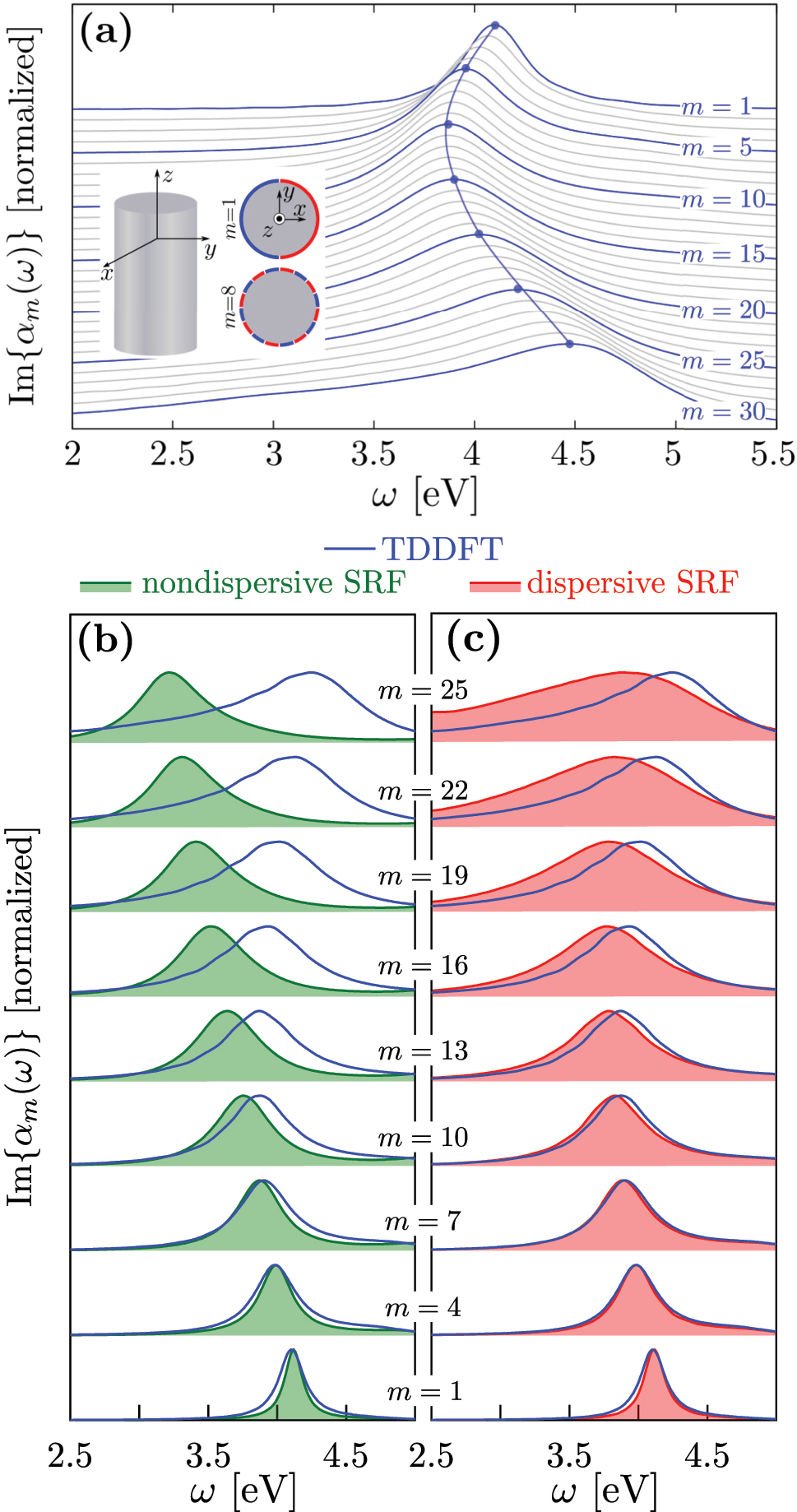
Imaginary part of the multipololar polarizability of order m, Im{α m (ω)}, of a Na nanowire of radius R c = 150 a 0 (≈8 nm). Results are shown as a function of the frequency of the excitation, ω, for different values of the magnetic quantum number m. Each spectrum of Im{α m (ω)} is normalized to 1 at its maximum, and vertically offset for clarity. (a) Real-time TDDFT results with m ranging from m = 1 (top) to m = 30 (bottom). The blue curves are labeled with the corresponding value of m, and the gray curves correspond to intermediate values. (b, c) Nondispersive SRF (b, green filled curves), dispersive SRF (c, red filled curves) and real-time TDDFT (blue lines) results with m ranging from m = 1 (bottom) to m = 25 (top). The dispersive and nondispersive SRF results are obtained from Eq. (7).
The close correspondence between the m-dependence of the frequency of the LMPs of the nanowire and the k
‖-dispersion of the surface plasmon resonances at the planar metal–vacuum interface can be understood as follows. By introducing the coordinate r
‖ along the circumference of the cylinder, r
‖ = R
c
φ, the angular dependence of the induced electric fields and surface electron densities of the LMPs transforms to
To support the equivalence between k
‖ and |m|/R
c
, we show in Figure 3b the plasmon frequency ω
m
of cylinders with different radii as a function of
Owing to the equivalence
where ɛ(ω) is the dielectric function of the metal described here with a Drude model (bulk plasma frequency ω
p
= 5.89 eV and intrinsic damping parameter γ
p
= 0.1 eV [75]). In Eq. (7),
Figure 4b and c show the result of Im{α m (ω)} for a Na nanowire, as obtained from Eq. (7) using the nondispersive SRF and the dispersive SRF, respectively. Again, the nondispersive SRF (panel b, green filled curves) erroneously predicts a continuous redshift of the localized multipolar plasmon of order m in the nanowire with increasing m. On the other hand, the dispersive SRF (panel c, red filled curves) correctly reproduces the general behavior of plasmon resonances when compared to the TDDFT results (redshift with increasing m for low m, and blueshift for larger m). The results shown in Figure 4 thus confirm that the dispersive SRF can be used to model the nonlocal optical response of a cylindrical nanowire of small radius where the field localization and oscillation in space can be extreme.
3.2.3 Individual spherical nanoparticles and nanoparticle dimers
We finally show that the dispersive SRF employed in this work can also be used to account for quantum surface effects and nonlocality in the optical response of plasmonic nanostructures with finite extension along the three spatial dimensions. As a first canonical plasmonic nanostructure, we consider a spherical Na metal nanoparticle (MNP) of radius a = 65.83 a
0
The spectrum of LMPs in spherical MNPS is determined by the nonretarded multipolar polarizability α ℓ (ω), which is given within the SRF by [56, 70]
We compare in Figure 5a the imaginary part of α ℓ (ω), Im{α ℓ (ω)}, obtained for different values of ℓ from TDDFT (blue lines), nondispersive SRF (left, green filled curves) and dispersive SRF (right, red filled curves). Details on the TDDFT calculations are given in ref. [75]. The LMPs of order ℓ appear as resonances in Im{α ℓ } associated with an increased absorption.
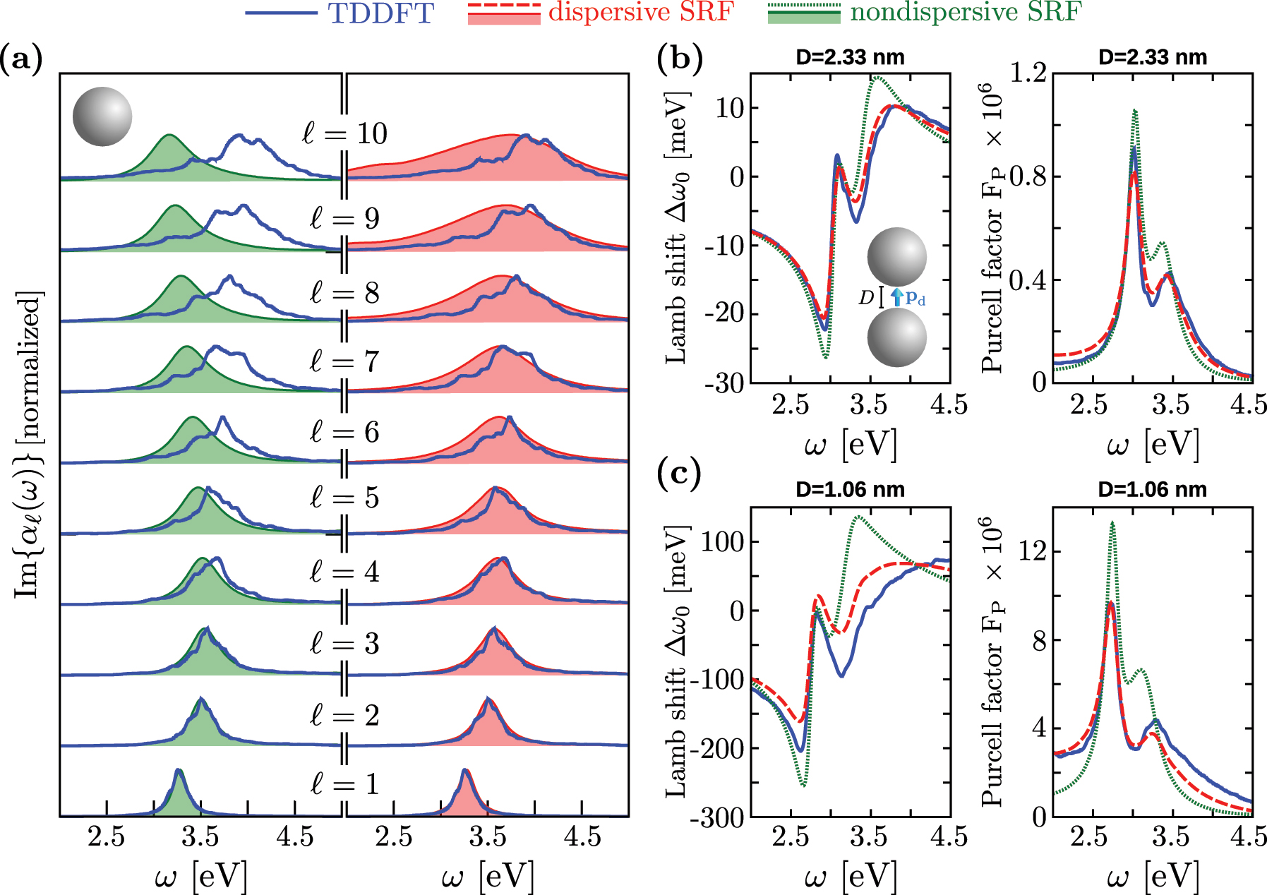
Comparison between the TDDFT (blue), dispersive SRF (red), and nondispersive SRF (green) results of the optical properties of individual spherical MNPs and dimers. (a) Imaginary part of the first ten multipolar polarizabilities α
ℓ
(ω) (ℓ = 1 − 10) of an individual spherical MNP. The left-hand side panel shows the comparison between TDDFT (blue lines) and nondispersive SRF (green filled curves) results, whereas the right-hand side panel shows the comparison between TDDFT and dispersive SRF (red filled curves) results. Each spectrum of Im{α
ℓ
(ω)} is normalized to 1 at its maximum, and vertically offset for clarity. (b, c) Lamb shift Δω
0 (left-hand side panels) and Purcell factor FP (right-hand side panels) obtained for a point-dipole emitter located at the center of a dimer of spherical MNPs of radius a = 65.83 a
0
The TDDFT results of Im{α
ℓ
(ω)} in Figure 5a show that the LMP of order ℓ continuously blueshifts with increasing ℓ in the considered range ℓ = 1 − 10. The resonance broadens as ℓ increases due to the enhancement of surface-enabled Landau damping. In this situation, the coupling of the plasmon to electron–hole pair excitations and quantum finite-size effects lead to the emergence of discrete spectral features [42, 62] (notice that these features merge into a smooth resonant profile in the metallic nanowires studied above because of their larger radius). As already stated in ref. [75], the nondispersive SRF accurately reproduces the TDDFT results for low values of ℓ ∼ 1 − 4, but it cannot describe the correct behavior for larger angular momenta. Indeed, within the nondispersive SRF the plasmon resonances start to redshift with increasing ℓ for ℓ ≥ 5 (left-hand side panel in Figure 5a). On the other hand, when accounting for the dependence of the Feibelman parameter d
⊥ on the effective wavenumber
Finally, we address another canonical plasmonic system: a dimer of spherical MNPs forming a plasmonic gap. Specifically, we study the case of a point-dipole emitter located at the center of the gap of size D formed by two identical spherical MNPs of radius a = 65.83 a
0
Figure 5b shows the Lamb shift Δω 0 (left) and Purcell factor F P (right) obtained for a gap separation D = 2.33 nm, as calculated within the three models tested here (TDDFT, dispersive SRF, and nondispersive SRF). The three approximations show qualitatively good agreement. For this relatively large gap, the excitation of low-ℓ LMP resonances dominates the response of the MNPs dimer [75], validating the long-wavelength approximation behind the nondispersive SRF results for D = 2.33 nm. Note, nonetheless, that the results obtained within the dispersive SRF are more accurate when comparing to those obtained within TDDFT.
The significant improvement introduced by the dispersive SRF to describe the emitter–dimer electromagnetic interaction is more evident when considering a smaller gap, where field localization and thus higher multipolar activation occurs. Figure 5c shows the Lamb shift and Purcell factor obtained for a gap separation D = 1.06 nm. In this situation, because of the larger spatial confinement of the charges induced at the metallic surfaces across the gap, plasmon modes with high multipolar order ℓ become important. These high-ℓ modes show overlapping resonant frequencies and thus contribute to a single broad peak (referred to as pseudomode [108, 109]) at ω ∼ 3.4 eV as revealed by the TDDFT calculations (blue lines). Since the nondispersive model does not describe accurately high-ℓ multipolar modes for the individual MNP (Figure 5a), it clearly fails to reproduce the frequency and the width of the plasmon pseudomode obtained within TDDFT. As a consequence, the nondispersive SRF strongly overestimates the overlap between the pseudomode and the bonding dipolar plasmon resonance at ω ∼ 2.75 − 3 eV (green dotted lines), as observed in the Purcell factor and the Lamb shift. On the other hand, the dispersive SRF (red dashed lines) provides accurate results even for this small gap separation, further illustrating its ability to account for nonlocality in situations where plasmon-induced charges characterized by a rapid variation in the direction parallel to the metal surface are excited.
4 Summary and conclusions
We have introduced a dispersive surface-response formalism (SRF) that incorporates quantum surface effects and nonlocality into the optical response of plasmonic nanostructures via the so-called Feibelman parameters. While the nondispersive SRF typically implemented in the literature is based on the Feibelman parameter d ⊥(ω) obtained within the long-wavelength limit (k ‖ = 0), the dispersive SRF proposed here is based on a dispersive Feibelman parameter d ⊥(ω, k ‖) that explicitly depends on the wavenumber parallel to the metal surface, k ‖. We obtain the values of d ⊥(ω, k ‖) from quantum many-body calculations for a planar metal–vacuum interface, and use a recent formulation of the electromagnetic boundary conditions [59] to account for the nonlocality of the dynamical screening in the direction parallel to the metal surface in various nanostructures.
Using TDDFT calculations as a reference, we have demonstrated that the dispersive SRF is significantly more accurate than the nondispersive SRF in describing plasmonic systems characterized by extremely confined induced fields. We have first shown that the dispersive SRF correctly describes the nonlocal dynamical screening of a planar metal surface and provides with the correct surface plasmon frequency dispersion with k
‖. Further, we have demonstrated that the Feibelman parameter d
⊥(ω, k
‖) calculated in this work using a planar metal surface can also be used to address the nonlocal optical response of nonplanar nanostructures relevant in plasmonics. As examples, we have considered infinite cylindrical nanowires, spherical metallic nanoparticles, and nanoparticle dimers forming gaps described within the free-electron metal approximation. The symmetry of these nanostructures allowed us to introduce geometry-dependent effective parallel wavenumbers,
In all these systems, the dispersive SRF reproduces the TDDFT results that naturally incorporate quantum effects such as nonlocal dynamical screening, surface-enabled Landau damping, and the finite spatial extension of the induced electron density at the metal surface. This work thus establishes a milestone for the development of a theoretical model that captures quantum surface effects and nonlocality in extreme situations of field localization, while keeping the numerical efficiency and easy implementation of classical (local) electromagnetic theories [59, 110, 111]. Among others, our findings can be important for describing the optical response of metallic nanostructures interacting with fast electrons, nanoantennas coupled to molecules in close proximity, metallic nanoparticles with geometrical features characterized by small radii of curvature (such as picocavities), or nanoparticle ensembles with narrow gaps, all of them relevant situations in practical configurations of nowadays Nanophotonics.
Funding source: Ministerio de Ciencia e Innovación
Award Identifier / Grant number: MCIN/AEI/10.13039/501100011033/PID2019-107432GB-I0
Funding source: Investissements d’Avenir LabEx PALM
Award Identifier / Grant number: ANR-10-LABX-0039-PALM
Award Identifier / Grant number: IT1526-22
-
Author contributions: All authors have accepted responsibility for the entire content of this manuscript and approved its submission.
-
Research funding: MCIN/AEI/10.13039/501100011033/ (PID2019-107432GB-I00); Department of Education of the Basque Government (IT1526-22); “Investissements d’Avenir” LabEx PALM (ANR-10-LABX-0039-PALM).
-
Conflict of interest statement: Authors state no conflicts of interest.
-
Data availability: The datasets generated and/or analysed during the current study are available from the corresponding author upon reasonable request.
References
[1] R. Zhang, Y. Zhang, Z. C. Dong, et al.., “Chemical mapping of a single molecule by plasmon-enhanced Raman scattering,” Nature, vol. 498, no. 7452, p. 82, 2013. https://doi.org/10.1038/nature12151.Search in Google Scholar PubMed
[2] J. R. Lakowicz, Principles of Fluorescence Spectroscopy, Berlin, Springer Science & Business Media, 2013.Search in Google Scholar
[3] E. Fort and S. Grésillon, “Surface enhanced fluorescence,” J. Phys. D Appl. Phys., vol. 41, no. 1, p. 013001, 2007. https://doi.org/10.1088/0022-3727/41/1/013001.Search in Google Scholar
[4] S. N. Gupta, O. Bitton, T. Neuman, et al.., “Complex plasmon-exciton dynamics revealed through quantum dot light emission in a nanocavity,” Nat. Commun., vol. 12, no. 1, pp. 1–9, 2021. https://doi.org/10.1038/s41467-021-21539-z.Search in Google Scholar PubMed PubMed Central
[5] B. Doppagne, T. Neuman, R. Soria-Martinez, et al.., “Single-molecule tautomerization tracking through space-and time-resolved fluorescence spectroscopy,” Nat. Nanotechnol., vol. 15, no. 3, pp. 207–211, 2020. https://doi.org/10.1038/s41565-019-0620-x.Search in Google Scholar PubMed
[6] B. Yang, G. Chen, A. Ghafoor, et al.., “Sub-nanometre resolution in single-molecule photoluminescence imaging,” Nat. Photonics, vol. 14, no. 11, pp. 693–699, 2020. https://doi.org/10.1038/s41566-020-0677-y.Search in Google Scholar
[7] R. Bardhan, S. Lal, A. Joshi, and N. J. Halas, “Theranostic nanoshells: from probe design to imaging and treatment of cancer,” Accounts Chem. Res., vol. 44, no. 10, pp. 936–946, 2011. https://doi.org/10.1021/ar200023x.Search in Google Scholar PubMed PubMed Central
[8] T. L. Doane and C. Burda, “The unique role of nanoparticles in nanomedicine: imaging, drug delivery and therapy,” Chem. Soc. Rev., vol. 41, no. 7, pp. 2885–2911, 2012. https://doi.org/10.1039/c2cs15260f.Search in Google Scholar PubMed
[9] A. R. Rastinehad, H. Anastos, E. Wajswol, et al.., “Gold nanoshell-localized photothermal ablation of prostate tumors in a clinical pilot device study,” Proc. Natl. Acad. Sci., vol. 116, no. 37, pp. 18590–18596, 2019. https://doi.org/10.1073/pnas.1906929116.Search in Google Scholar PubMed PubMed Central
[10] H. A. Atwater and A. Polman, “Plasmonics for improved photovoltaic devices,” in Materials for Sustainable Energy: A Collection of Peer-Reviewed Research and Review Articles from Nature Publishing Group, 2011, pp. 1–11.10.1142/9789814317665_0001Search in Google Scholar
[11] S. Carretero-Palacios, A. Jiménez-Solano, and H. Míguez, “Plasmonic nanoparticles as light-harvesting enhancers in perovskite solar cells: a user’s guide,” ACS Energy Lett., vol. 1, no. 1, pp. 323–331, 2016. https://doi.org/10.1021/acsenergylett.6b00138.Search in Google Scholar PubMed PubMed Central
[12] S. K. Cushing and N. Wu, “Progress and perspectives of plasmon-enhanced solar energy conversion,” J. Phys. Chem. Lett., vol. 7, no. 4, pp. 666–675, 2016. https://doi.org/10.1021/acs.jpclett.5b02393.Search in Google Scholar PubMed
[13] M. Kauranen and A. V. Zayats, “Nonlinear plasmonics,” Nat. Photonics, vol. 6, no. 11, p. 737, 2012. https://doi.org/10.1038/nphoton.2012.244.Search in Google Scholar
[14] A. V. Krasavin, P. Ginzburg, and A. V. Zayats, Nonlinear Nanoplasmonics, Cham, Springer International Publishing, 2019, pp. 267–316.10.1007/978-3-319-98402-5_8Search in Google Scholar
[15] K. J. Savage, M. M. Hawkeye, R. Esteban, A. G. Borisov, J. Aizpurua, and J. J. Baumberg, “Revealing the quantum regime in tunnelling plasmonics,” Nature, vol. 491, no. 7425, pp. 574–577, 2012. https://doi.org/10.1038/nature11653.Search in Google Scholar PubMed
[16] J. A. Scholl, A. García-Etxarri, A. L. Koh, and J. A. Dionne, “Observation of quantum tunneling between two plasmonic nanoparticles,” Nano Lett., vol. 13, no. 2, pp. 564–569, 2013. https://doi.org/10.1021/nl304078v.Search in Google Scholar PubMed
[17] G. Hajisalem, M. S. Nezami, and R. Gordon, “Probing the quantum tunneling limit of plasmonic enhancement by third harmonic generation,” Nano Lett., vol. 14, no. 11, pp. 6651–6654, 2014. https://doi.org/10.1021/nl503324g.Search in Google Scholar PubMed
[18] S. F. Tan, L. Wu, J. K. Yang, P. Bai, M. Bosman, and C. A. Nijhuis, “Quantum plasmon resonances controlled by molecular tunnel junctions,” Science, vol. 343, no. 6178, pp. 1496–1499, 2014. https://doi.org/10.1126/science.1248797.Search in Google Scholar PubMed
[19] H. Cha, J. H. Yoon, and S. Yoon, “Probing quantum plasmon coupling using gold nanoparticle dimers with tunable interparticle distances down to the subnanometer range,” ACS Nano, vol. 8, no. 8, pp. 8554–8563, 2014. https://doi.org/10.1021/nn5032438.Search in Google Scholar PubMed
[20] W. Zhu and K. B. Crozier, “Quantum mechanical limit to plasmonic enhancement as observed by surface-enhanced Raman scattering,” Nat. Commun., vol. 5, no. 1, pp. 1–8, 2014. https://doi.org/10.1038/ncomms6228.Search in Google Scholar PubMed
[21] F. Benz, M. K. Schmidt, A. Dreismann, et al.., “Single-molecule optomechanics in “picocavities”,” Science, vol. 354, no. 6313, pp. 726–729, 2016. https://doi.org/10.1126/science.aah5243.Search in Google Scholar PubMed
[22] A. Babaze, R. Esteban, A. G. Borisov, and J. Aizpurua, “Electronic exciton–plasmon coupling in a nanocavity beyond the electromagnetic interaction picture,” Nano Lett., vol. 21, no. 19, pp. 8466–8473, 2021. https://doi.org/10.1021/acs.nanolett.1c03202.Search in Google Scholar PubMed
[23] N. A. Mortensen, “Mesoscopic electrodynamics at metal surfaces,” Nanophotonics, vol. 10, no. 10, pp. 2563–2616, 2021. https://doi.org/10.1515/nanoph-2021-0156.Search in Google Scholar
[24] P. E. Stamatopoulou and C. Tserkezis, “Finite-size and quantum effects in plasmonics: manifestations and theoretical modelling,” Opt. Mater. Express, vol. 12, no. 5, pp. 1869–1893, 2022. https://doi.org/10.1364/ome.456407.Search in Google Scholar
[25] F. J. García de Abajo, “Nonlocal effects in the plasmons of strongly interacting nanoparticles, dimers, and waveguides,” J. Phys. Chem. C, vol. 112, no. 46, pp. 17983–17987, 2008. https://doi.org/10.1021/jp807345h.Search in Google Scholar
[26] G. Toscano, “Semiclassical theory of nonlocal plasmonic excitation in metallic nanostructures,” Ph.D. thesis, Technical University of Denmark, 2013.Search in Google Scholar
[27] T. V. Teperik, P. Nordlander, J. Aizpurua, and A. G. Borisov, “Robust subnanometric plasmon ruler by rescaling of the nonlocal optical response,” Phys. Rev. Lett., vol. 110, no. 26, p. 263901, 2013. https://doi.org/10.1103/physrevlett.110.263901.Search in Google Scholar PubMed
[28] T. V. Teperik, P. Nordlander, J. Aizpurua, and A. G. Borisov, “Quantum effects and nonlocality in strongly coupled plasmonic nanowire dimers,” Opt. Express, vol. 21, pp. 27306–27325, 2013. https://doi.org/10.1364/oe.21.027306.Search in Google Scholar PubMed
[29] L. Stella, P. Zhang, F. García-Vidal, A. Rubio, and P. García-González, “Performance of nonlocal optics when applied to plasmonic nanostructures,” J. Phys. Chem. C, vol. 117, no. 17, pp. 8941–8949, 2013. https://doi.org/10.1021/jp401887y.Search in Google Scholar
[30] S. Raza, S. I. Bozhevolnyi, M. Wubs, and N. A. Mortensen, “Nonlocal optical response in metallic nanostructures,” J. Phys. Condens. Matter, vol. 27, no. 18, p. 183204, 2015. https://doi.org/10.1088/0953-8984/27/18/183204.Search in Google Scholar PubMed
[31] P. Apell and Å. Ljungbert, “Red shift of surface plasmons in small metal particles,” Solid State Commun., vol. 44, no. 9, pp. 1367–1369, 1982. https://doi.org/10.1016/0038-1098(82)90895-x.Search in Google Scholar
[32] A. Liebsch, Electronic Excitations at Metal Surfaces, Berlin, Springer Science & Business Media, 1997.10.1007/978-1-4757-5107-9Search in Google Scholar
[33] C. Ciracì and F. D. Sala, “Quantum hydrodynamic theory for plasmonics: impact of the electron density tail,” Phys. Rev. B, vol. 93, no. 20, p. 205405, 2016. https://doi.org/10.1103/physrevb.93.205405.Search in Google Scholar
[34] E. J. Skjølstrup, T. Søndergaard, and T. G. Pedersen, “Quantum spill-out in few-nanometer metal gaps: effect on gap plasmons and reflectance from ultrasharp groove arrays,” Phys. Rev. B, vol. 97, no. 11, p. 115429, 2018. https://doi.org/10.1103/physrevb.97.115429.Search in Google Scholar
[35] J. Zuloaga, E. Prodan, and P. Nordlander, “Quantum description of the plasmon resonances of a nanoparticle dimer,” Nano Lett., vol. 9, no. 2, pp. 887–891, 2009. https://doi.org/10.1021/nl803811g.Search in Google Scholar PubMed
[36] G. Aguirregabiria, D. C. Marinica, R. Esteban, A. K. Kazansky, J. Aizpurua, and A. G. Borisov, “Role of electron tunneling in the nonlinear response of plasmonic nanogaps,” Phys. Rev. B, vol. 97, no. 11, p. 115430, 2018. https://doi.org/10.1103/physrevb.97.115430.Search in Google Scholar
[37] E. Runge and E. K. Gross, “Density-functional theory for time-dependent systems,” Phys. Rev. Lett., vol. 52, no. 12, p. 997, 1984. https://doi.org/10.1103/physrevlett.52.997.Search in Google Scholar
[38] E. Gross and W. Kohn, “Time-dependent density-functional theory,” in Density Functional Theory of Many-Fermion Systems. Advances in Quantum Chemistry, vol. 21, P.-O. Löwdin, Ed., Cambridge, Academic Press, 1990, pp. 255–291.10.1016/S0065-3276(08)60600-0Search in Google Scholar
[39] M. Marques and E. Gross, “Time-dependent density functional theory,” Annu. Rev. Phys. Chem., vol. 55, no. 1, pp. 427–455, 2004. https://doi.org/10.1146/annurev.physchem.55.091602.094449.Search in Google Scholar PubMed
[40] C. A. Ullrich, Time-Dependent Density-Functional Theory: Concepts and Applications, Oxford, Oxford University Press, 2013.Search in Google Scholar
[41] K. Yabana and G. Bertsch, “Time-dependent local-density approximation in real time,” Phys. Rev. B, vol. 54, no. 7, p. 4484, 1996. https://doi.org/10.1103/physrevb.54.4484.Search in Google Scholar PubMed
[42] A. Varas, P. García-González, J. Feist, F. García-Vidal, and A. Rubio, “Quantum plasmonics: from jellium models to ab initio calculations,” Nanophotonics, vol. 5, no. 3, pp. 409–426, 2016. https://doi.org/10.1515/nanoph-2015-0141.Search in Google Scholar
[43] M. R. A. Barbry, “Plasmons in nanoparticles: atomistic Ab Initio theory for large systems,” Ph.D. thesis, University of the Basque Country, 2018.Search in Google Scholar
[44] R. Esteban, A. G. Borisov, P. Nordlander, and J. Aizpurua, “Bridging quantum and classical plasmonics with a quantum-corrected model,” Nat. Commun., vol. 3, no. 1, pp. 1–9, 2012. https://doi.org/10.1038/ncomms1806.Search in Google Scholar PubMed
[45] Y. Luo, A. Fernandez-Dominguez, A. Wiener, S. A. Maier, and J. Pendry, “Surface plasmons and nonlocality: a simple model,” Phys. Rev. Lett., vol. 111, no. 9, p. 093901, 2013. https://doi.org/10.1103/physrevlett.111.093901.Search in Google Scholar
[46] R. Esteban, A. Zugarramurdi, P. Zhang, et al.., “A classical treatment of optical tunneling in plasmonic gaps: extending the quantum corrected model to practical situations,” Faraday Discuss, vol. 178, pp. 151–183, 2015. https://doi.org/10.1039/c4fd00196f.Search in Google Scholar PubMed
[47] M. Zapata, A. S. C. Beltrán, A. G. Borisov, and J. Aizpurua, “Quantum effects in the optical response of extended plasmonic gaps: validation of the quantum corrected model in core-shell nanomatryushkas,” Opt. Express, vol. 23, no. 6, pp. 8134–8149, 2015. https://doi.org/10.1364/oe.23.008134.Search in Google Scholar
[48] W. Zhu, R. Esteban, A. G. Borisov, et al.., “Quantum mechanical effects in plasmonic structures with subnanometre gaps,” Nat. Commun., vol. 7, no. 1, pp. 1–14, 2016. https://doi.org/10.1038/ncomms11495.Search in Google Scholar PubMed PubMed Central
[49] D. Knebl, A. Hörl, A. Trügler, et al.., “Gap plasmonics of silver nanocube dimers,” Phys. Rev. B, vol. 93, p. 081405, 2016. https://doi.org/10.1103/physrevb.93.081405.Search in Google Scholar
[50] N. A. Mortensen, S. Raza, M. Wubs, T. Søndergaard, and S. I. Bozhevolnyi, “A generalized non-local optical response theory for plasmonic nanostructures,” Nat. Commun., vol. 5, no. 1, pp. 1–7, 2014. https://doi.org/10.1038/ncomms4809.Search in Google Scholar PubMed
[51] G. Toscano, J. Straubel, A. Kwiatkowski, et al.., “Resonance shifts and spill-out effects in self-consistent hydrodynamic nanoplasmonics,” Nat. Commun., vol. 6, p. 7132, 2015. https://doi.org/10.1038/ncomms8132.Search in Google Scholar PubMed
[52] S. Raza, M. Wubs, S. I. Bozhevolnyi, and N. A. Mortensen, “Nonlocal study of ultimate plasmon hybridization,” Opt. Lett., vol. 40, pp. 839–842, 2015. https://doi.org/10.1364/ol.40.000839.Search in Google Scholar PubMed
[53] M. Kupresak, X. Zheng, G. A. Vandenbosch, and V. V. Moshchalkov, “Comparison of hydrodynamic models for the electromagnetic nonlocal response of nanoparticles,” Adv. Theory Simul., vol. 1, no. 12, p. 1800076, 2018. https://doi.org/10.1002/adts.201800076.Search in Google Scholar
[54] A. Rivacoba, “Electron spill-out effects in plasmon excitations by fast electrons,” Ultramicroscopy, vol. 207, p. 112835, 2019. https://doi.org/10.1016/j.ultramic.2019.112835.Search in Google Scholar PubMed
[55] H. M. Baghramyan, F. Della Sala, and C. Ciracì, “Laplacian-level quantum hydrodynamic theory for plasmonics,” Phys. Rev. X, vol. 11, p. 011049, 2021. https://doi.org/10.1103/physrevx.11.011049.Search in Google Scholar
[56] P. Apell and Å. Ljungbert, “A general non-local theory for the electromagnetic response of a small metal particle,” Phys. Scr., vol. 26, no. 2, p. 113, 1982. https://doi.org/10.1088/0031-8949/26/2/010.Search in Google Scholar
[57] R. C. Monreal, T. J. Antosiewicz, and S. P. Apell, “Competition between surface screening and size quantization for surface plasmons in nanoparticles,” New J. Phys., vol. 15, no. 8, p. 083044, 2013. https://doi.org/10.1088/1367-2630/15/8/083044.Search in Google Scholar
[58] W. Yan, M. Wubs, and N. A. Mortensen, “Projected dipole model for quantum plasmonics,” Phys. Rev. Lett., vol. 115, p. 137403, 2015. https://doi.org/10.1103/physrevlett.115.137403.Search in Google Scholar
[59] Y. Yang, D. Zhu, W. Yan, et al.., “A general theoretical and experimental framework for nanoscale electromagnetism,” Nature, vol. 576, no. 7786, pp. 248–252, 2019. https://doi.org/10.1038/s41586-019-1803-1.Search in Google Scholar PubMed
[60] P. J. Feibelman, “Surface electromagnetic fields,” Prog. Surf. Sci., vol. 12, no. 4, pp. 287–407, 1982. https://doi.org/10.1016/0079-6816(82)90001-6.Search in Google Scholar
[61] J. D. Jackson, Classical Electrodynamics, New York, Wiley, 1999.Search in Google Scholar
[62] C. Yannouleas and R. Broglia, “Landau damping and wall dissipation in large metal clusters,” Ann. Phys., vol. 217, no. 1, pp. 105–141, 1992. https://doi.org/10.1016/0003-4916(92)90340-r.Search in Google Scholar
[63] A. Vagov, I. Larkin, M. D. Croitoru, and V. M. Axt, “Role of nonlocality and Landau damping in the dynamics of a quantum dot coupled to surface plasmons,” Phys. Rev. B, vol. 93, no. 19, p. 195414, 2016. https://doi.org/10.1103/physrevb.93.195414.Search in Google Scholar
[64] J. Khurgin, W.-Y. Tsai, D. P. Tsai, and G. Sun, “Landau damping and limit to field confinement and enhancement in plasmonic dimers,” ACS Photonics, vol. 4, no. 11, pp. 2871–2880, 2017. https://doi.org/10.1021/acsphotonics.7b00860.Search in Google Scholar
[65] A. Liebsch, “Surface-plasmon dispersion and size dependence of mie resonance: silver versus simple metals,” Phys. Rev. B, vol. 48, no. 15, p. 11317, 1993. https://doi.org/10.1103/physrevb.48.11317.Search in Google Scholar PubMed
[66] P. Apell, “A simple derivation of the surface contribution to the reflectivity of a metal, and its use in the van der waals interaction,” Phys. Scr., vol. 24, no. 4, p. 795, 1981. https://doi.org/10.1088/0031-8949/24/4/019.Search in Google Scholar
[67] T. Christensen, W. Yan, A.-P. Jauho, M. Soljačić, and N. A. Mortensen, “Quantum corrections in nanoplasmonics: shape, scale, and material,” Phys. Rev. Lett., vol. 118, no. 15, p. 157402, 2017. https://doi.org/10.1103/physrevlett.118.157402.Search in Google Scholar
[68] A. J. Shvonski, J. Kong, and K. Kempa, “Nonlocal extensions of the electromagnetic response of plasmonic and metamaterial structures,” Phys. Rev. B, vol. 95, p. 045149, 2017. https://doi.org/10.1103/physrevb.95.045149.Search in Google Scholar
[69] J. Kong, A. J. Shvonski, and K. Kempa, “Nonlocal response with local optics,” Phys. Rev. B, vol. 97, p. 165423, 2018. https://doi.org/10.1103/physrevb.97.165423.Search in Google Scholar
[70] P. Gonçalves, T. Christensen, N. Rivera, A.-P. Jauho, N. A. Mortensen, and M. Soljačić, “Plasmon–emitter interactions at the nanoscale,” Nat. Commun., vol. 11, no. 1, pp. 1–13, 2020. https://doi.org/10.1038/s41467-019-13820-z.Search in Google Scholar PubMed PubMed Central
[71] A. R. Echarri, P. A. D. Gonçalves, C. Tserkezis, F. J. G. de Abajo, N. A. Mortensen, and J. D. Cox, “Optical response of noble metal nanostructures: quantum surface effects in crystallographic facets,” Optica, vol. 8, pp. 710–721, 2021. https://doi.org/10.1364/optica.412122.Search in Google Scholar
[72] N. A. Mortensen, P. Gonçalves, F. A. Shuklin, et al.., “Surface-response functions obtained from equilibrium electron-density profiles,” Nanophotonics, vol. 10, no. 14, pp. 3647–3657, 2021. https://doi.org/10.1515/nanoph-2021-0084.Search in Google Scholar
[73] V. Karanikolas, I. Thanopulos, J. D. Cox, et al.., “Quantum surface effects in strong coupling dynamics,” Phys. Rev. B, vol. 104, p. L201405, 2021. https://doi.org/10.1103/physrevb.104.l201405.Search in Google Scholar
[74] P. A. D. Gonçalves and F. J. García de Abajo, “Interrogating quantum nonlocal effects in nanoplasmonics through electron-beam spectroscopies,” Nano Lett., vol. 23, no. 10, pp. 4242–4249, 2023.10.1021/acs.nanolett.3c00298Search in Google Scholar PubMed
[75] A. Babaze, E. Ogando, P. E. Stamatopoulou, et al.., “Quantum surface effects in the electromagnetic coupling between a quantum emitter and a plasmonic nanoantenna: time-dependent density functional theory vs. semiclassical feibelman approach,” Opt. Express, vol. 30, no. 12, pp. 21159–21183, 2022. https://doi.org/10.1364/oe.456338.Search in Google Scholar
[76] O. Gunnarsson and B. I. Lundqvist, “Exchange and correlation in atoms, molecules, and solids by the spin-density-functional formalism,” Phys. Rev. B, vol. 13, no. 10, p. 4274, 1976. https://doi.org/10.1103/physrevb.13.4274.Search in Google Scholar
[77] W. Ekardt, “Dynamical polarizability of small metal particles: self-consistent spherical jellium background model,” Phys. Rev. Lett., vol. 52, no. 21, p. 1925, 1984. https://doi.org/10.1103/physrevlett.52.1925.Search in Google Scholar
[78] W. Ekardt, “Work function of small metal particles: self-consistent spherical jellium-background model,” Phys. Rev. B, vol. 29, no. 4, p. 1558, 1984. https://doi.org/10.1103/physrevb.29.1558.Search in Google Scholar
[79] W. Ekardt, “Quantum size effects in the electronic properties of small metal particles: self-consistent spherical jellium background model,” Surf. Sci., vols. 152–153, pp. 180–188, 1985. https://doi.org/10.1016/0039-6028(85)90141-4.Search in Google Scholar
[80] M. Brack, “The physics of simple metal clusters: self-consistent jellium model and semiclassical approaches,” Rev. Mod. Phys., vol. 65, no. 3, p. 677, 1993. https://doi.org/10.1103/revmodphys.65.677.Search in Google Scholar
[81] M. Koskinen, P. Lipas, and M. Manninen, “Electron-gas clusters: the ultimate jellium model,” Z. Physik D Atoms Mol. Clust., vol. 35, no. 4, pp. 285–297, 1995. https://doi.org/10.1007/bf01745532.Search in Google Scholar
[82] V. M. Silkin, J. M. Pitarke, E. V. Chulkov, and P. M. Echenique, “Acoustic surface plasmons in the noble metals cu, ag, and au,” Phys. Rev. B, vol. 72, no. 11, p. 115435, 2005. https://doi.org/10.1103/physrevb.72.115435.Search in Google Scholar
[83] U. Hohenester, Nano and Quantum Optics, Berlin, Springer, 2020.10.1007/978-3-030-30504-8Search in Google Scholar
[84] J. Pitarke, V. Silkin, E. Chulkov, and P. Echenique, “Theory of surface plasmons and surface-plasmon polaritons,” Rep. Prog. Phys., vol. 70, no. 1, p. 1, 2006. https://doi.org/10.1088/0034-4885/70/1/r01.Search in Google Scholar
[85] A. J. Bennett, “Influence of the electron charge distribution on surface-plasmon dispersion,” Phys. Rev. B, vol. 1, no. 1, p. 203, 1970. https://doi.org/10.1103/physrevb.1.203.Search in Google Scholar
[86] A. Kawabata and R. Kubo, “Electronic properties of fine metallic particles. ii. plasma resonance absorption,” J. Phys. Soc. Jpn., vol. 21, no. 9, pp. 1765–1772, 1966. https://doi.org/10.1143/jpsj.21.1765.Search in Google Scholar
[87] E. Zaremba and B. N. J. Persson, “Dynamic polarizability of small metal particles,” Phys. Rev. B, vol. 35, pp. 596–606, 1987. https://doi.org/10.1103/physrevb.35.596.Search in Google Scholar PubMed
[88] K.-D. Tsuei, E. Plummer, A. Liebsch, K. Kempa, and P. Bakshi, “Multipole plasmon modes at a metal surface,” Phys. Rev. Lett., vol. 64, no. 1, p. 44, 1990. https://doi.org/10.1103/physrevlett.64.44.Search in Google Scholar PubMed
[89] H. Ishida and A. Liebsch, “Lifetime of surface plasmons of simple metals: volume versus surface contributions,” Phys. Rev. B, vol. 54, pp. 14127–14133, 1996. https://doi.org/10.1103/physrevb.54.14127.Search in Google Scholar PubMed
[90] W. Ekardt, “Size-dependent photoabsorption and photoemission of small metal particles,” Phys. Rev. B, vol. 31, pp. 6360–6370, 1985. https://doi.org/10.1103/physrevb.31.6360.Search in Google Scholar PubMed
[91] G. D. Mahan, “Lifetime of surface plasmons,” Phys. Rev. B, vol. 97, p. 075405, 2018. https://doi.org/10.1103/physrevb.97.075405.Search in Google Scholar
[92] C. Kunz, “Messung charakteristischer energieverluste von elektronen an leichtoxydierbaren metallen im ultrahochvakuum,” Z. Phys., vol. 196, no. 4, pp. 311–331, 1966. https://doi.org/10.1007/bf01325652.Search in Google Scholar
[93] K.-D. Tsuei, E. Plummer, A. Liebsch, E. Pehlke, K. Kempa, and P. Bakshi, “The normal modes at the surface of simple metals,” Surf. Sci., vol. 247, nos. 2–3, pp. 302–326, 1991. https://doi.org/10.1016/0039-6028(91)90142-f.Search in Google Scholar
[94] P. Sprunger, G. Watson, and E. Plummer, “The normal modes at the surface of li and mg,” Surf. Sci., vol. 269, pp. 551–555, 1992. https://doi.org/10.1016/0039-6028(92)91307-w.Search in Google Scholar
[95] V. M. Silkin, E. V. Chulkov, and P. M. Echenique, “Band structure versus dynamical exchange-correlation effects in surface plasmon energy and damping: a first-principles calculation,” Phys. Rev. Lett., vol. 93, no. 17, p. 176801, 2004. https://doi.org/10.1103/physrevlett.93.176801.Search in Google Scholar PubMed
[96] J. Harris and A. Griffin, “Surface plasmon dispersion,” Phys. Lett. A, vol. 34, no. 1, pp. 51–52, 1971. https://doi.org/10.1016/0375-9601(71)90994-7.Search in Google Scholar
[97] F. Flores and F. Garcia-Moliner, “Model-independent theory of surface plasmons,” Solid State Commun., vol. 11, no. 9, pp. 1295–1298, 1972. https://doi.org/10.1016/0038-1098(72)90846-0.Search in Google Scholar
[98] A. Liebsch, “Dynamical screening at simple-metal surfaces,” Phys. Rev. B, vol. 36, pp. 7378–7388, 1987. https://doi.org/10.1103/physrevb.36.7378.Search in Google Scholar PubMed
[99] G. Aguirregabiria, D.-C. Marinica, M. Ludwig, et al.., “Dynamics of electron-emission currents in plasmonic gaps induced by strong fields,” Faraday Discuss., vol. 214, pp. 147–157, 2019. https://doi.org/10.1039/c8fd00158h.Search in Google Scholar PubMed
[100] M. Ludwig, G. Aguirregabiria, F. Ritzkowsky, et al.., “Sub-femtosecond electron transport in a nanoscale gap,” Nat. Phys., vol. 16, no. 3, pp. 341–345, 2020. https://doi.org/10.1038/s41567-019-0745-8.Search in Google Scholar
[101] D. C. Marinica, M. Zapata, P. Nordlander, et al.., “Active quantum plasmonics,” Sci. Adv., vol. 1, no. 11, p. e1501095, 2015. https://doi.org/10.1126/sciadv.1501095.Search in Google Scholar PubMed PubMed Central
[102] A. Babaze, R. Esteban, J. Aizpurua, and A. G. Borisov, “Second-harmonic generation from a quantum emitter coupled to a metallic nanoantenna,” ACS Photonics, vol. 7, no. 3, pp. 701–713, 2020. https://doi.org/10.1021/acsphotonics.9b01569.Search in Google Scholar
[103] F.-P. Schmidt, H. Ditlbacher, U. Hohenester, A. Hohenau, F. Hofer, and J. R. Krenn, “Universal dispersion of surface plasmons in flat nanostructures,” Nat. Commun., vol. 5, no. 1, pp. 1–6, 2014. https://doi.org/10.1038/ncomms4604.Search in Google Scholar PubMed PubMed Central
[104] E. Townsend and G. W. Bryant, “Which resonances in small metallic nanoparticles are plasmonic?” J. Opt., vol. 16, no. 11, p. 114022, 2014. https://doi.org/10.1088/2040-8978/16/11/114022.Search in Google Scholar
[105] R. Zhang, L. Bursi, J. D. Cox, et al.., “How to identify plasmons from the optical response of nanostructures,” ACS Nano, vol. 11, no. 7, pp. 7321–7335, 2017. https://doi.org/10.1021/acsnano.7b03421.Search in Google Scholar PubMed PubMed Central
[106] C. Ciracì, R. Jurga, M. Khalid, and F. Della Sala, “Plasmonic quantum effects on single-emitter strong coupling,” Nanophotonics, vol. 8, no. 10, pp. 1821–1833, 2019. https://doi.org/10.1515/nanoph-2019-0199.Search in Google Scholar
[107] L. Novotny and B. Hecht, Principles of Nano-Optics, Cambridge, Cambridge University Press, 2012.10.1017/CBO9780511794193Search in Google Scholar
[108] A. Delga, J. Feist, J. Bravo-Abad, and F. Garcia-Vidal, “Theory of strong coupling between quantum emitters and localized surface plasmons,” J. Opt., vol. 16, no. 11, p. 114018, 2014. https://doi.org/10.1088/2040-8978/16/11/114018.Search in Google Scholar
[109] T. Neuman, R. Esteban, D. Casanova, F. García-Vidal, and J. Aizpurua, “Coupling of molecular emitters and plasmonic cavities beyond the point-dipole approximation,” Nano Lett., vol. 18, no. 4, pp. 2358–2364, 2018. https://doi.org/10.1021/acs.nanolett.7b05297.Search in Google Scholar PubMed
[110] C. Tao, Y. Zhong, and H. Liu, “Quasinormal mode expansion theory for mesoscale plasmonic nanoresonators: an analytical treatment of nonclassical electromagnetic boundary condition,” Phys. Rev. Lett., vol. 129, no. 19, p. 197401, 2022. https://doi.org/10.1103/physrevlett.129.197401.Search in Google Scholar
[111] U. Hohenester and G. Unger, “Nanoscale electromagnetism with the boundary element method,” Phys. Rev. B, vol. 105, no. 7, p. 075428, 2022. https://doi.org/10.1103/physrevb.105.075428.Search in Google Scholar
Supplementary Material
This article contains supplementary material (https://doi.org/10.1515/nanoph-2023-0178).
© 2023 the author(s), published by De Gruyter, Berlin/Boston
This work is licensed under the Creative Commons Attribution 4.0 International License.
Articles in the same Issue
- Frontmatter
- Research Articles
- Non-dispersive Fano resonances in hybrid plasmonic-distributed Bragg reflector structures
- Temperature invariant metasurfaces
- Microfiber evanescent-field photothermal gas detection using acoustic-induced mode-dependent frequency shift
- Single chip simultaneous chiral and achiral imaging based on high efficiency 3D plasmonic metalens
- Two-dimensional heterostructure quasi-BIC photonic crystal surface-emitting laser with low divergence
- Observation of ultra-large Rabi splitting in the plasmon-exciton polaritons at room temperature
- Dispersive surface-response formalism to address nonlocality in extreme plasmonic field confinement
- Impact of substrates and quantum effects on exciton line shapes of 2D semiconductors at room temperature
- Dispersion engineering of infrared epsilon-near-zero modes by strong coupling to optical cavities
- Resonant inelastic tunneling using multiple metallic quantum wells
- Label-free, ultra-low detection limit DNA biosensor using high quality optical microcavity functionalized by DNA tetrahedral nanostructure probes
- Tunable magnetless optical isolation with twisted Weyl semimetals
- Encoding Mie, plasmonic, and diffractive structural colors in the same pixel
- Highly directional single-photon source
- Terahertz all-silicon metasurfaces with off-axis bifocal characteristics for polarization detection
- Dynamic ultraviolet harmonic beam pattern control by programmable spatial wavefront modulation of near-infrared fundamental beam
- Realizing depth measurement and edge detection based on a single metasurface
- Erratum
- Erratum to: Supercontinuum in integrated photonics: generation, applications, challenges and perspectives