Abstract
Glasses-free three-dimensional (3D) display has attracted wide interest for providing stereoscopic virtual contents with depth cues. However, how to achieve high spatial and angular resolution while keeping ultrawide field of view (FOV) remains a significant challenge in 3D display. Here, we propose a light field 3D display with space-variant resolution for non-uniform distribution of information and energy. The spatial resolution of each view is modulated according to watching habit. A large-scale combination of pixelated 1D and 2D metagratings is used to manipulate dot and horizontal line views. With the joint modulation of pixel density and view arrangement, the information density and illuminance of high-demand views are at most 5.6 times and 16 times that of low-demand views, respectively. Furthermore, a full-color and video rate light field 3D display with non-uniform information distribution is demonstrated. The prototype provides 3D images with a high spatial resolution of 119.6 pixels per inch and a high angular resolution of 0.25 views per degree in the high-demand views. An ultrawide viewing angle of 140° is also provided. The proposed light field 3D display does not require ultrahigh-resolution display panels and has form factors of thin and light. Thus, it has the potential to be used in portable electronics, window display, exhibition display, as well as tabletop display.
1 Introduction
Glasses-free three-dimensional (3D) displays have attracted great attention. The potential applications include intelligent manufacturing, telemedicine, automobile, and social networking [1–6]. Because of its thin form factor, light field 3D display is one of the glasses-free 3D display technologies that may re-define the information interaction in portable electronics [7–15]. Generally speaking, spatial and angular resolutions are both important parameters to evaluate the display performance in a 3D display system [7].
The angular resolution of a light field 3D display is defined as the view density, i.e. the number of views within the unit viewing angle.
where Δθ is the angular separation of views. The units of angular resolution are views per degree (vpd). The spatial resolution is defined as pixel density with a unit of pixel per inch (ppi). The information density is further adopted to define the display information within the unit viewing angle:
where N mul is the pixel number of images at each view. The units of information density are pixels per degree (ppd).
Low spatial resolution may lead to clear pixelation effect, while low angular resolution causes discontinuous motion parallax. An ideal 3D virtual scene provides both high spatial and angular resolution for observers. Unfortunately, when total information is limited, there exists a fundamental trade-off between spatial resolution, angular resolution and field of view (FOV) (Figure S1).
Screen splicing strategy is an effective method to improve the total refreshable information, thus improving the 3D visual perception [16–18]. For example, four 8 K liquid crystal display (LCD) panels were combined to improve the display performance in an integral display [16]. The multi-screen splicing display prototype provided integral 3D images with a spatial resolution of 25 ppi within a viewing angle of 28°. The time-multiplexed scheme is another method to increase the amount of display information [19–22]. An angular steering screen was adopted to sequentially deflect light beams [19]. The prototype can produce smooth horizontal parallax with an angular resolution of 1 vpd within the horizontal viewing angle of ∼31°. Yet, increasing the information of display panel is bound to create stringent demands on panel fabrication, image rendering, circuit driving, system complexity and real-time data transport.
The human-centered mechanism inspired us with an alternative strategy to address the trade-off between spatial resolution, angular resolution and field of view [23, 24]. For example, the on-demand distribution is a human-centered strategy in the fields of sociology, economics and energy storage, which is used to handle the increasing number of requests against limited social resources [25–32]. Similarly, when the total information resource is limited, non-uniform distribution of information according to watching habit is preferable, although uniformly distributed information is taken as granted and widely adopted in all kinds of 3D displays.
Our group has proposed foveated glasses-free 3D display by creating space-variant view distribution via the 2D-metagrating complex [33]. A video-rate full color 3D display was demonstrated with an unprecedented 160° horizontal viewing angle and a spatial resolution of 52 ppi. The 2D-metagrating complex is designed by encoding the multiple periods and multiple orientations of the nanostructures in each pixel. The pixelated 2D metagrating modulates the phase of incident light for different output diffraction angles that generates the space-variant views [34, 35]. With the non-uniform angular sampling, the trade-off between angular resolution and FOV is solved. However, the low spatial resolution still needs to be improved.
In this paper, we further propose a light field 3D display with a non-uniform distribution of information and energy based on human watching habit of display screen. The rendered parallax images are non-uniformly projected to viewing regions through metagrating complex. For those frequently observed regions (called ‘high-demand view’), high spatial resolution images are projected to dot-shaped views with high angular resolution. For the less frequently observed region (called ‘low-demand view’), relatively low spatial resolution images are reconstructed in line-shaped views. Furthermore, the brightness of high-demand view and low-demand view is also distributed non-uniformly for the best usage of energy.
In the experiment, a large-scale metagrating complex (18 cm × 11.3 cm) with more than 12 million pixelated metagrating is fabricated. Integrated with an off-the-shelf purchased display panel (total pixel number: 2560 × 1600), a video-rate full color light field 3D display is demonstrated. The spatial resolution is increased up to 119.6 ppi and the angular resolution is enhanced up to 0.25 vpd at the high-demand views. The system also provides an ultrawide viewing angle of 140°. The proposed system requires neither ultra-high-resolution display panels nor time-/spatial-multiplexing architectures, thus it features the potential applications in portable electronic devices by integrating with commercially available display panels.
2 Light field 3D display with space-variant resolution
Figure 1 illustrates the system configuration of the proposed light field 3D display. The prototype has a compact form factor and is composed of a view modulator and a display panel. For illustration purpose, a voxel on an LCD panel contains 3 × 3 pixels. In the traditional strategy, each pixel in a voxel is usually directed to one view [12, 36]. As a result, 9 views with uniformly distributed spatial and angular resolution are rendered. Here we redistribute each pixel so that the spatial resolution of 3D image at the high-demand view is increased. With the space-variant pixel numbers, the spatial resolution of the display prototype is redistributed non-uniformly.
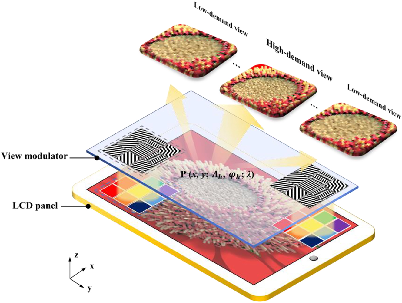
Schematic diagram of the proposed light field 3D display with space-variant resolution.
Moreover, the space-variant angular resolution is enabled by the view modulator. The view modulator covered with metagrating complex is aligned with the LCD panel pixel by pixel. The metagrating complex is designed to tailor the output diffraction angles. The angular divergence of diffractive beam in horizontal direction spans from 1° to 10°. As a result, when a collimated white light illuminates on the prototype, the light field 3D display with space-variant resolution is achieved. The strategy of space-variant resolution seems straightforward but is nontrivial. It should be noted that the light field from each pixel need to be manipulated independently. Light modulation at pixel level can hardly be achieved by traditional geometric optics, such as lenticular lens, or microlens.
2.1 Modulation method for space-variant spatial resolution
Generally speaking, a multi-view camera system or a 3D computer graphic software is used to capture 2D images from different perspectives. We refer to these individual perspective images as parallax images. As shown in Figure 2A, seven ‘astrological symbol’ parallax images are captured at seven views, respectively. The pixel number is decreased from 600 × 200 at View 4 to 100 × 200 at View 1, 7. A Gaussian-like distribution of pixel number along views provide significantly increased spatial resolution at high-demand view (Figure 2B).
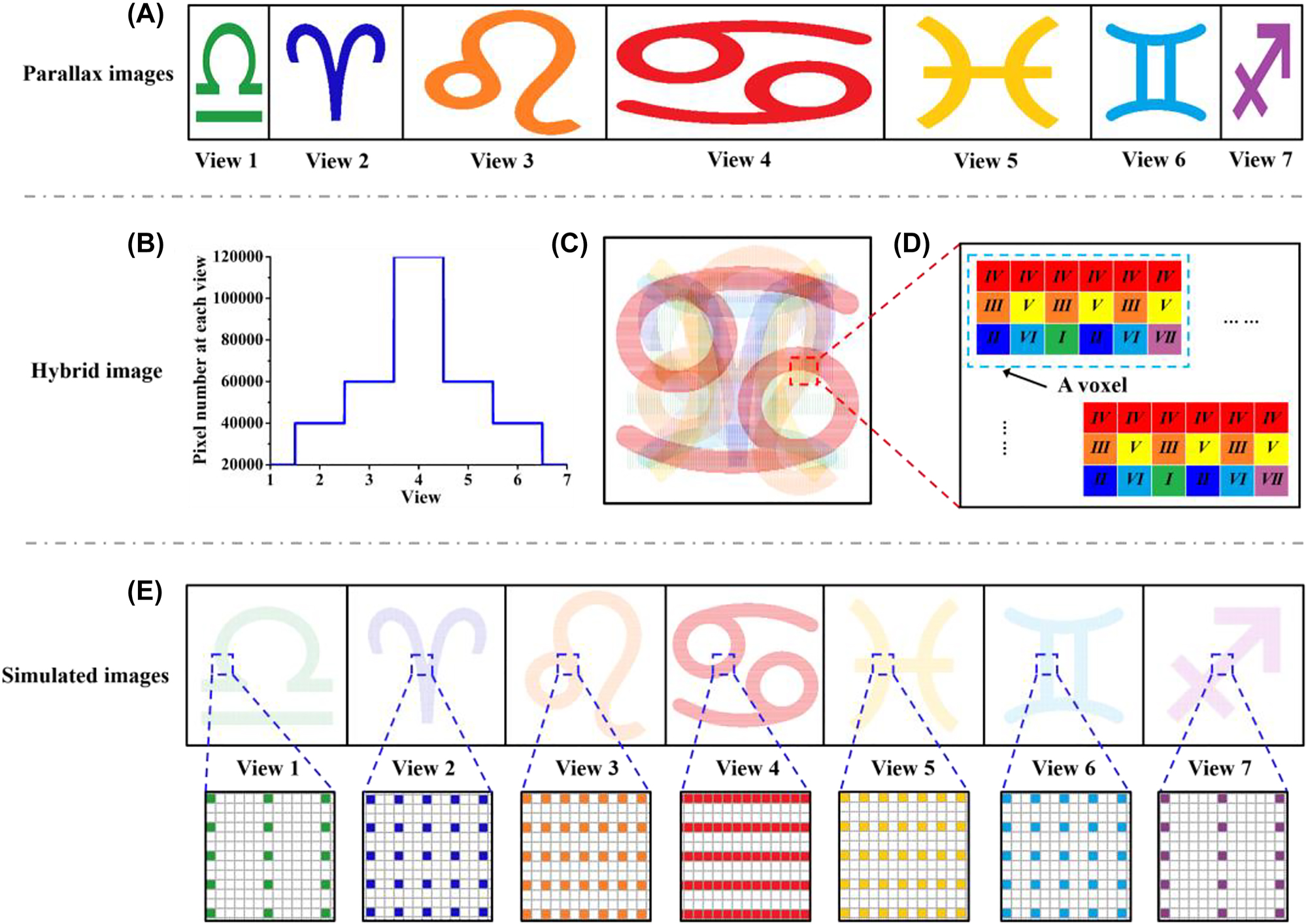
Schematic of the modulation method of spatial resolution in the horizontal direction. (A) Seven ‘astrological symbol’ parallax images with various pixel number in the horizontal direction. The pixel number is 100 × 200 at View 1 & 7, 200 × 200 at View 2 & 6, 300 × 200 at View 3 & 5 and 600 × 200 at View 4, respectively. (B) Distribution of pixel number at each view. (C) The hybrid image which contains seven parallax images. (D) Schematic of the arrangement of pixels in the voxels. There are 6 × 3 pixels in one voxel. (E) The simulated images observed at each view.
Then the hybrid image is created by merging a series of parallax images, as shown in Figure 2C. The total pixel number of hybrid image is 600 × 600. In traditional voxel arrangement, each voxel contains 7 pixels with one pixel from each view. In contrast, one pixel from View 1, 7, two pixels from View 2, 6, three pixels from View 3, 5, and six pixels from View 4 attribute to a voxel (Figure 2D). As a result, a voxel consists of 6 × 3 pixels and the total voxel number is (600 ÷ 6) × (600 ÷ 3) = 100 × 200. Therefore, the spatial resolution of high-demand view is increased to 171 ppi at View 4, while the spatial resolutions of low-demand views are decreased to 97 ppi at View 3, 5, 76 ppi at View 2, 6 and 60 ppi at View 1, 7 (Figure 2E). With the non-uniform pixel arrangement, the spatial resolution and the brightness are variant in space. Moreover, other possible strategies of spatial resolution modulation are provided in Section S2 in the Supplementary material.
2.2 Modulation method for space-variant angular resolution
The general grating equation for an arbitrary obliquely incident beam can be written in direction cosine space based on the Raman–Nath regime [37].
where α i , β i , α m, and β m are the direction cosines of the incident beam and diffraction beam, respectively, λ is the wavelength of beam, m is the diffraction order, n is the refraction index, Λ h and φ h are the multiple periods and multiple orientations of the metagrating, respectively, and h is the period serial number in the metagrating pixel (h = 1,2,3 …). Combining Eq. (3) and Eq. (4), the structural parameters of metagratings (Λ h and φ h ) are calculated pixel by pixel [33, 35]. Therefore, the metagrating complex controls the emitting light direction at pixel-level with a high precision, which can be expressed as follows [38, 39]:
where (x, y) are the coordinate values of the pixel on the view modulator plane. 1D metagratings converge the emitting light from the LCD panel to form dot shaped views in the central region. 2D metagratings reconstruct the phase of the emitting beam to form horizontal line shaped views in the periphery region. With the non-uniform view distribution, the angular resolution is modulated to be variant in the space.
In the proposed prototype, the angular separation of dot shaped views (high-demand views) and line shaped views (low-demand views) are set as 4° and 10°, respectively. Therefore, the angular resolution of the high-demand view is at most 2.5 times that of low-demand views. Figure 3A and B show the simulated radiation pattern and intensity distribution along the horizontal direction. The simulated diffraction efficiencies are 15.5% and 6.6% for 1D metagratings and 2D metagratings (λ = 530 nm) with a depth of 200 nm. The crosstalk of the central view is around 2%.
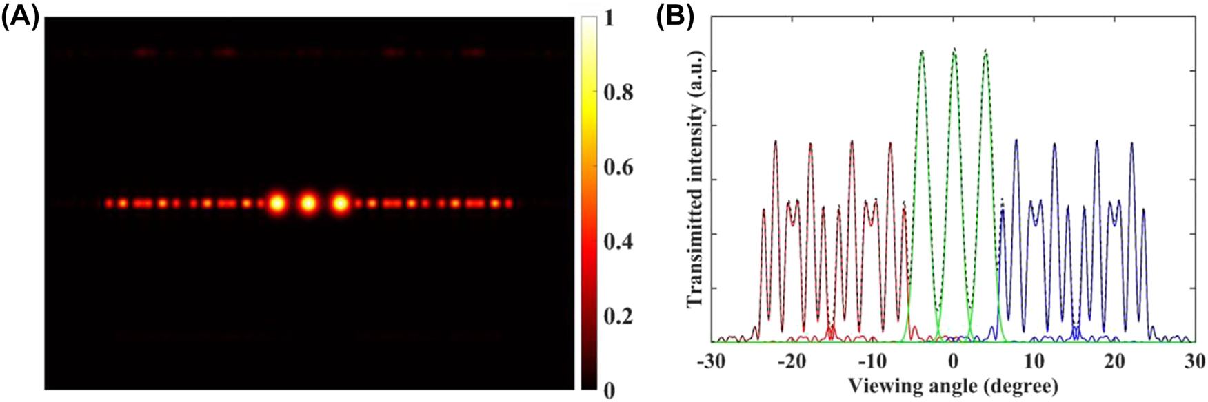
The finite-difference time-domain (FDTD) simulation of the metagrating complex. (A) The 2D radiation pattern from the metagrating complex. The dot shaped views are distributed in the center region, while the line shaped views are arranged on both edges. (B) The intensity distribution along the horizontal direction.
3 Design and fabrication of metagrating complex
The pixelated metagrating complex plays a crucial role in the proposed display system to form the non-uniform distribution of information density and energy. A home-made light field direct writing system is built to pattern metagratings pixel by pixel [40, 41]. Figure 4 shows the design and fabrication process of the metagrating complex. Firstly, we adopt a weighted G-S algorithm to generate the phase hologram based on the target view [42, 43]. Then the phase hologram is transformed into a BOE grating on glass substrate after laser direct writing (LDW) and dry etching process. The reconstructed image of the fabricated BOE grating has line shaped irradiance under the illumination of a 532 nm laser (Figure 4A). The prepared BOE grating is inserted into the light field direct writing system. By moving and rotating the inserted BOE grating between two Fourier transform lens within the system, metagratings are fabricated with predesigned multiple periods and orientations [44]. We take the microscopic image and magnified SEM images of metagratings, respectively (Figure 4B and C). To prove the concept of the light field 3D display, a 3.7 inch view modulator and a shadow mask are fabricated, as shown in Figure 4D. The view modulator contains 200 × 200 voxels, and each voxel has 3 × 3 pixelated metagratings.
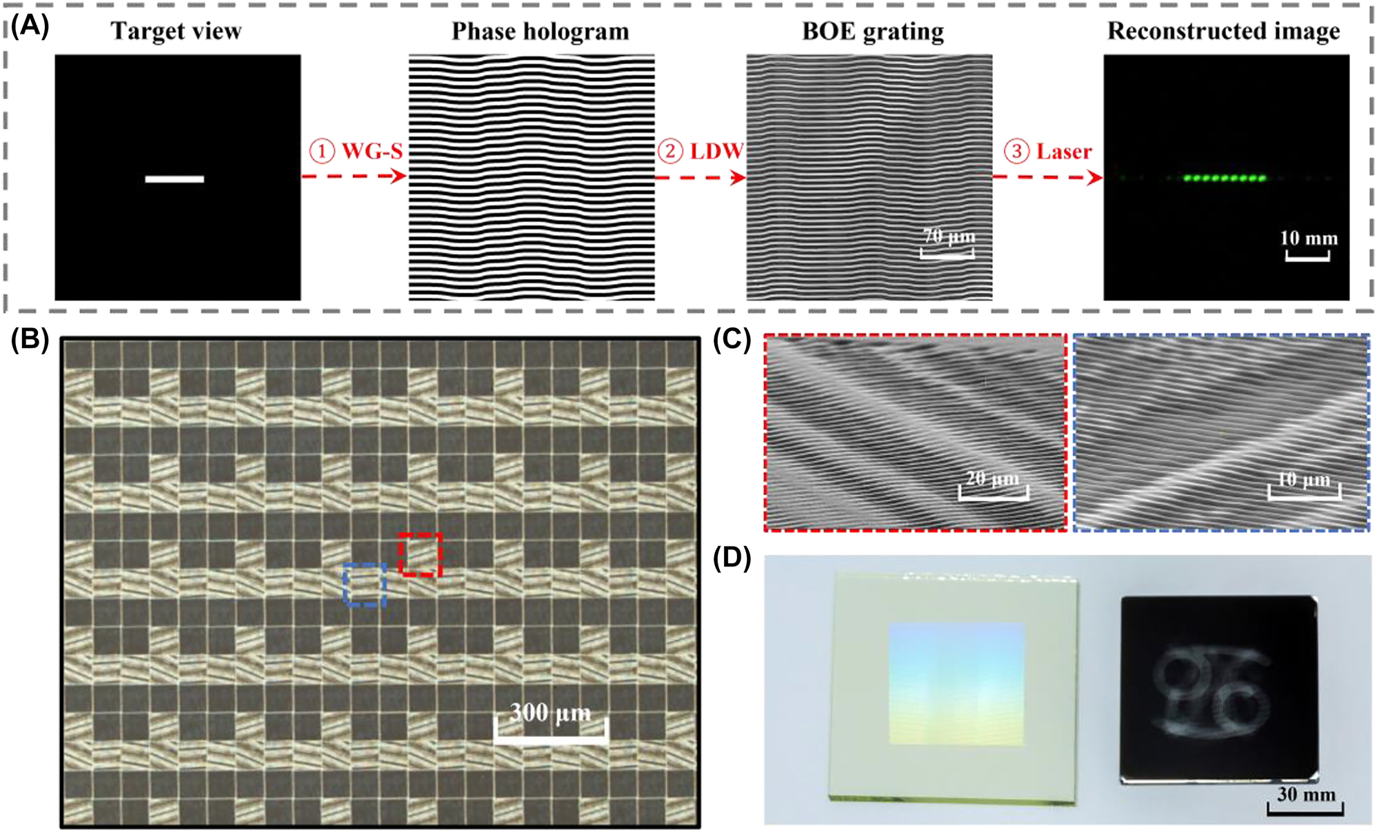
Design and fabrication flow of the metagrating complex: (A) design process of the BOE grating: ① generating the phase hologram using a weighted G-S algorithm; ② transforming the phase hologram into the BOE using laser direct writing; ③ reconstructing the target image using a 532 nm laser. (B) The microscope image of the pixelated metagrating complex. (C) Magnified SEM images of 2D metagratings. (D) Photo of the fabricated view modulator and a shadow mask.
Figure 5A presents the measured radiation pattern of the view modulator, under the illumination of a 532 nm laser source. Three dot-shaped views are distributed in the central region with an angular resolution of 0.25 vpd. The central views are sandwiched by four line-shaped views with an angular resolution of 0.1 vpd. Besides, the angular resolution of the region between dot-shaped views and line-shaped views is 0.17 vpd. The spatial resolution of the high-demand view is 2.2 times more than the spatial resolution of low-demand views. The typical parameters of the 3.7 inch view modulator are listed in Table 1. Figure 5B illustrates the distribution of spatial resolution, angular resolution, information density, and illuminance, respectively. With the joint modulation of pixel density and view arrangement, the information density of the high-demand view is increased to at most 5.6 times that of low-demand views.
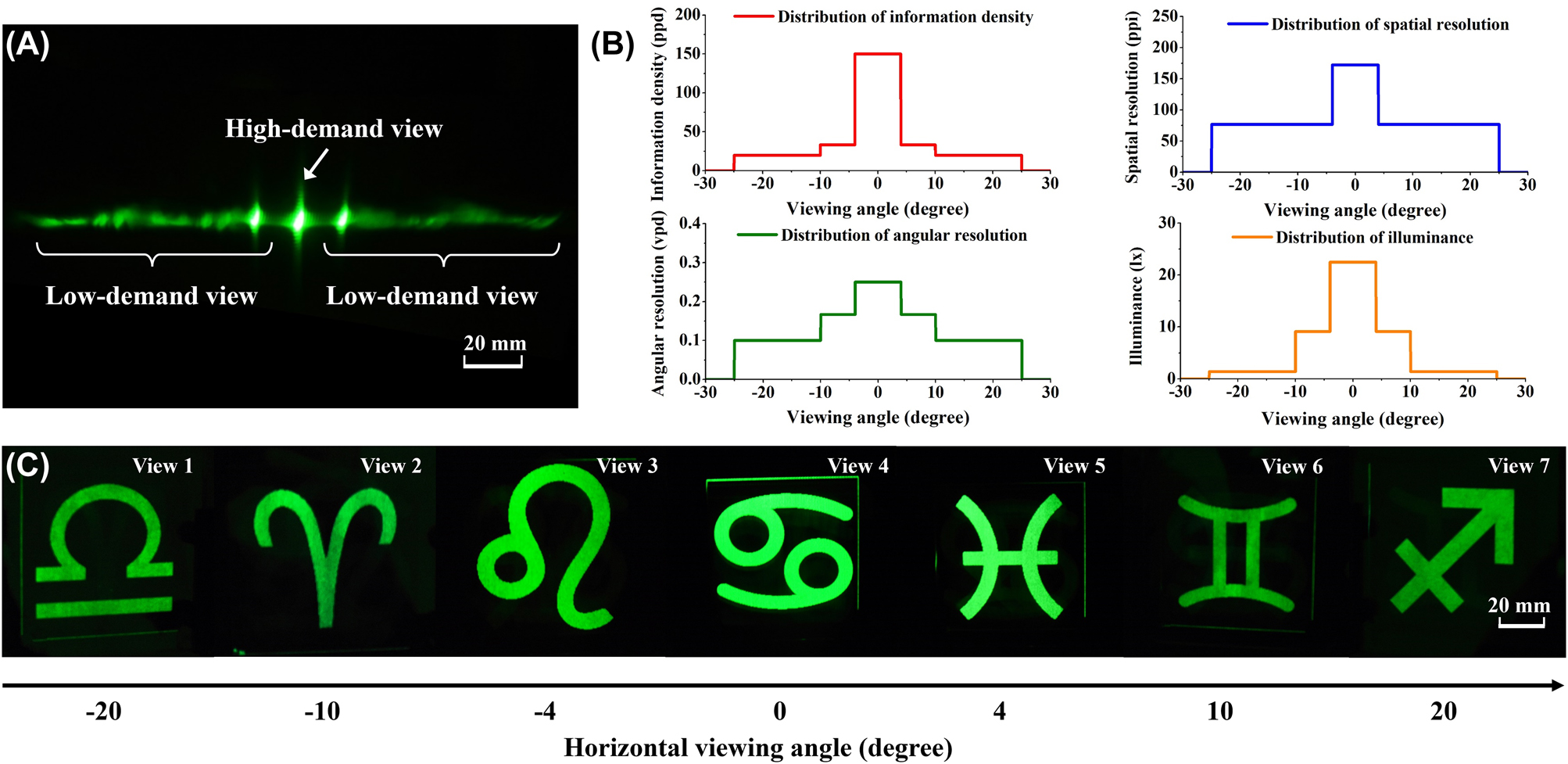
A monochromatic light field 3D display prototype with space-variant resolution: (A) the measured radiation pattern of the view modulator. (B) The distribution of spatial resolution, angular resolution, information density, and illuminance, respectively. (C) 3D images of astrological symbols observed from View 1–7.
Optical performance of three typical prototypes.
| 3D Imaging characteristics | View Modulator in Figure 5 | View Modulator in Figure 6 | View Modulator in Figure 8 |
|---|---|---|---|
| Frame size | 3.7 inch | 5.1 inch | 8.4 inch |
| View number | 7 | 24 | 24 |
| Number of pixels | 600 × 600 | 5400 × 1200 | 2560 × 1600 |
| Field of view | 50° | 140° | 140° |
| Spatial resolutiona | 170.9 ppi (H) | 361.6 ppi (H) | 119.6 ppi (H) |
| 76.4 ppi (L) | 180.8 ppi (L) | 59.8 ppi (L) | |
| Angular resolution | 0.25 vpd (H) | 0.25 vpd (H) | 0.25 vpd (H) |
| 0.17 vpd (L) | 0.2 vpd (L) | 0.2 vpd (L) | |
| 0.1 vpd (L) | 0.1 vpd (L) | 0.1 vpd (L) | |
| Information density | 158.1 ppd (H) | 461 ppd (H) | 251.1 ppd (H) |
| 47.1 ppd (L) | 184.4 ppd (L) | 100.4 ppd(L) | |
| 28.3 ppd (L) | 92.2 ppd (L) | 50.2 ppd (L) |
-
aH, high-demand view; L, low-demand view.
The space-variant information density is first tested by a monochromatic 3D image. A view modulator and a shadow mask are aligned pixel by pixel. Under the illumination of a green light-emitting diode (LED) light, seven astrological symbols are projected to each view, as shown in Figure 5C. The prospective images are well separated from the high-demand view and low-demand views (Visualization 1). The illuminance is further measured at each view. The illuminance decreases from 22.5 lx at View 4 to 1.4 lx at View 1, 2, 6, 7. Energy redistribution provides a strategy to minimize optical power consumption.
4 Characteristics of display prototype
To further validate the light field 3D display with space-variant resolution, multiple full-color view modulators with different frame sizes are fabricated. A full color light field 3D display is demonstrated by integrating a 5.1 inch view modulator and a shadow mask. Figure 6 shows the 3D images of ‘bees and flowers’ which are reassigned and redirected to various views. The spatial resolution of high-demand views (−6°, −2°, 2°, and 6°) are 2 times that of other views.
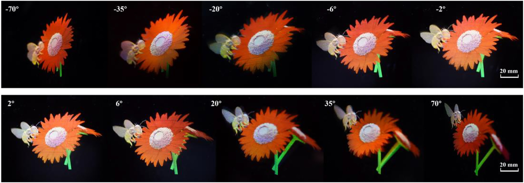
3D images of ‘bees and flowers’ observed from various views with natural motion parallax and color mixing.
We take a comparison between the high-demand view and low-demand view, as shown in Figure 7. The magnified images (bee’s head and pistil) at the high-demand view can express the details clearly, while the magnified images at the low-demand view become blurred due to the pixelation effect. The information density of high-demand views is increased up to 461 ppd, which is at most 5 times that of low-demand views.
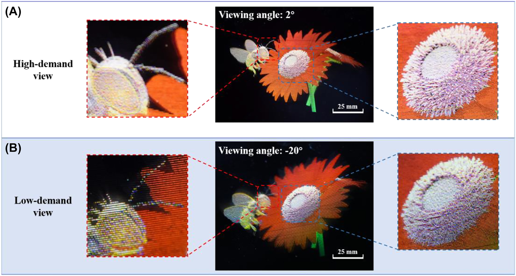
A comparison between the magnified photos taken at (A) the high-demand view, and (B) the low-demand view.
Furthermore, by integrating the view modulator with an 8.4 inch off-the-shelf LCD panel (M6, HUAWEI), a video rate and full color light field 3D display prototype is demonstrated. The typical parameters of the full color prototypes are listed in Table 1. Figure 8A depicts the individually modulated R/G/B subpixels for full color display, by stacking 2D metagratings, polarizers, color filters, and liquid crystals, successively. The prototype is achieved by aligning the view modulator and the LCD panel pixel by pixel via one-step bonding assembly (Figure 8B).
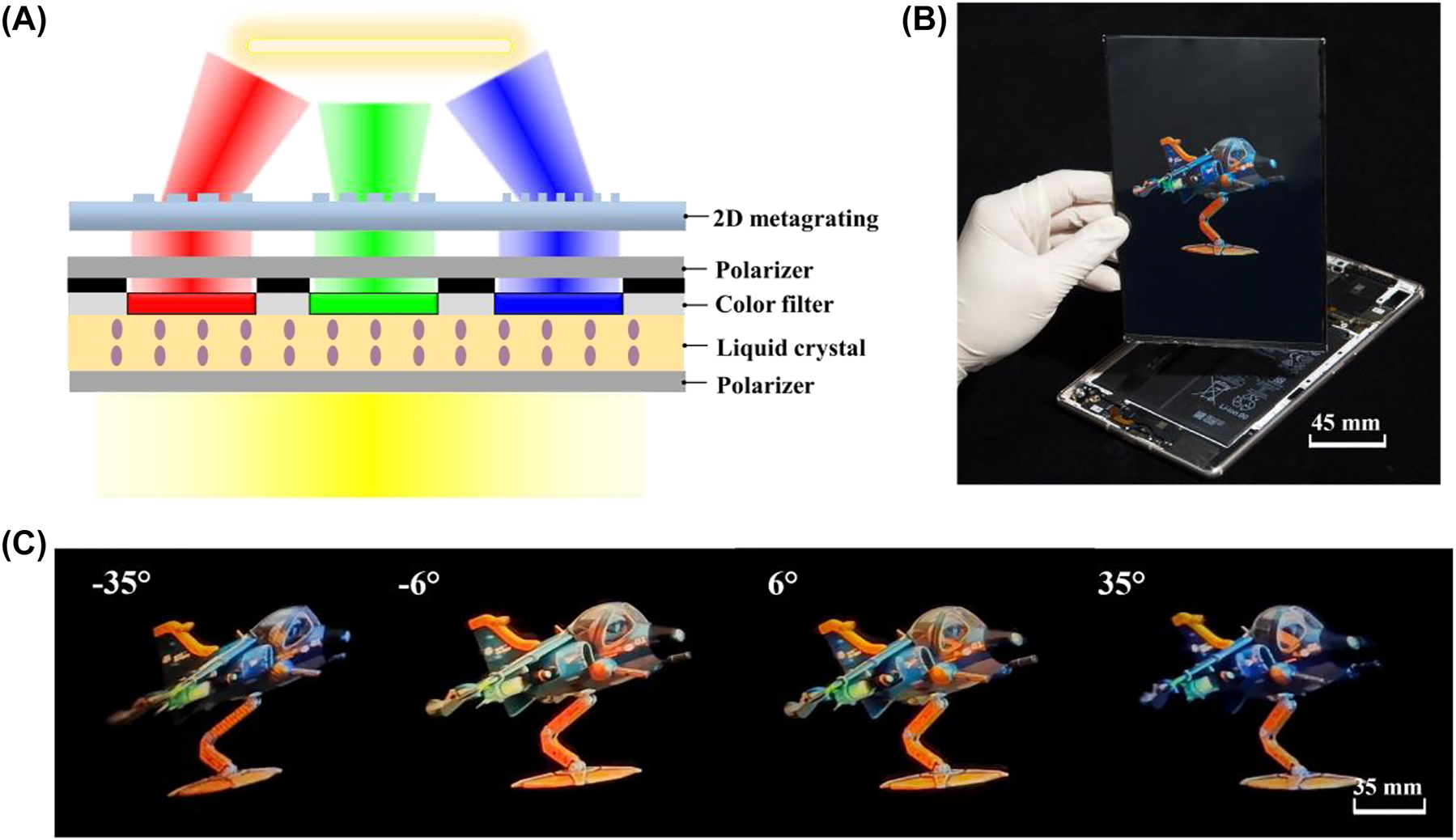
A full-color and video rate light field 3D display with space-variant resolution: (A) schematic of a combined pixel in the full color 3D display prototype. (B) A demo of the 8.4 inch light field 3D display. (C) 3D images of ‘cartoon plane’ observed from left to right views.
We capture images with a camera (D810, Nikon) at a viewing distance of 500 mm (Figure 8C and Figure S6). The proposed light field 3D display features high spatial resolution of 119.6 ppi and high angular resolution of 0.25 vpd at high-demand views. The viewing angle with continuous motion parallax is 140° (Visualization 2 & 3). The information density at high-demand views is increased up to 251.1 ppd.
Finally, we take a comparison between the conventional 3D display with uniform information distribution and the proposed 3D display with variant information distribution, as shown in Figure 9A. For a fair comparison, the total display information remains unchanged and set as 2560 × 1600. Benefiting from the non-uniform distribution strategy, the trade-off curve dramatically shifts right. To be specific, when the FOV is set as 140° and the angular resolution reaches 0.25 vpd, the pixel number is increased from 0.42 K to 0.83 K (From the red dot to the blue star). If we keep the pixel number at 0.83 K, the angular resolution is increased from 0.06 vpd to 0.25 vpd (From the blue dot to the blue star). The experimental results marked by the blue star demonstrate the feasibility of the method. We further compare the proposed work with prior art [33, 45], [46], [47], [48]. As shown in Figure 9B, the viewing angle is greatly expanded while maintaining a high spatial resolution and angular resolution at the high-demand views.

The proposed 3D display with variant information distribution and other 3D displays: (A) Schematic of the relationship between spatial resolution and angular resolution in two different modes. The blue star represents the parameters of the 8.4 inch light field 3D display prototype. The pixel number and angular resolution are 0.83 K (852 × 532) and 0.25 vpd at the high-demand views, respectively. (B) Comparison of the display performance between the proposed non-uniform strategy and the state-of-art 3D displays.
5 Discussion and conclusion
Based on the watching habits in the flat panel display, high-demand views are placed at the central region in current prototype. Yet the high-demand views can be placed in other areas. For example, in a vehicle dial display system, high-demand views are better concentrated in the periphery region. In a near-eye display, high-demand views should be shifted to where the eye gaze reaches.
Here we sandwiched high-demand views with low-demand views along the horizontal direction for horizontal parallax. Alternatively, vertical parallax and full parallax can be achieved by a group of dot/line/rectangle-shaped views [33].
To summarize, a facile and effective strategy for the light field 3D display with space-variant resolution was demonstrated. Non-uniform distribution of information and energy is achieved according to human watching habit. The pixel density of parallax images on various views is adjusted to achieve the variant spatial resolution. Meanwhile, the brightness of the parallax images also forms a non-uniform distribution. The light consumption at the low-demand views can be saved which makes the proposed light field 3D display energy efficient.
Using a homemade versatile light field direct writing system, multiple view modulators composed of 1D metagratings and 2D metagratings were fabricated with a frame size ranging from 3.7 inch to 8.4 inch. More than 12 million pixels of metagratings were patterned. Seven dot and line hybrid views with horizontal distribution were achieved. With the joint modulation of pixel density and view distribution, the information density and illuminance at the high-demand views were increased to at most 5.6 times and 16 times that of low-demand views.
Moreover, by integrating the view modulator with an 8.4 inch off-the-shelf purchased LCD panel, a video-rate and full-color display prototype was built. With total display information of 2560 × 1600, the prototype achieved a high spatial resolution of 119.6 ppi and a high angular resolution of 0.25 vpd at high-demand views. The prototype also provided an ultrawide motion parallax within 140°. In theory, the maximum viewing angle can reach 180° by properly designing the nanostructures. However, people seldom observe a display panel at an angle of ±90°. A FOV of ∼140° is adequate for portable electronics in most cases.
One should note that metagrating complex is not the only pattern that can achieve non-uniform information distribution. More complexed nanostructures [49] can be adopted to further improve the display performance in terms of FOV, light efficiency or depth of viewing distance. Yet the design and fabrication of sophisticated nanostructures over a function display size (larger than 4 inch) is a critical issue that hinders the advancement of nanophotonics based glasses-free 3D display.
The proposed light field 3D display featured thin and light form factors. We expect that it can be potentially applied in consumer electronic devices. Furthermore, future studies in the directional backlight module equipped with eye tracking system may open new avenues for its integration and commercialization.
6 Methods
6.1 Simulation section
The numerical simulations were completed in the FDTD software (FDTD solutions, Ansys/Lumerical). The 3D structure data of metagrating complex were imported into the FDTD as the form of GDSII (By LinkCAD). The refractive index of the photoresist was set as 1.62 (λ = 530 nm). The groove depth of structures was set as 200 nm. The pixel size was set as 30 µm. Two plane wave sources, which were served as natural light, illuminated on the metagrating complex with an incident angle of 30°. The boundary conditions were set as Bloch and perfect matching layer (PML) along transverse and longitudinal directions, respectively. The radiation pattern was produced in the far field projection of the monitors.
6.2 Fabrication section
For the inserted BOE gratings: First, we pre-cleaned a 2.5 inch quartz plate. The quartz substrate was then coated with HMDS (DisChem, SurPass 3000) and positive photoresist (AZ® P4620, MicroChemicals) sequentially. Second, the quartz plate was patterned with binary phase hologram using LDW system (MiScan, SVG optronics). The BOE gratings structure were fabricated through the photolithography and developed in NaOH solution. The concentration of NaOH solution was about 8‰. Third, to increase the photoresist durability, the BOE gratings were etched using the plasma etching system (NLD-570, ULVAC). As a result, the groove depth was approximately 600 nm and the average period was 7.5 µm. Finally, the BOE gratings were inserted in the versatile interference lithography to fabricate the metagrating complex.
For the view modulators: First, we pre-cleaned a glass plate. The size of glass plate was determined by the display frame size. The glass plate was then coated with HMDS and positive photoresist (RJZ-390, RUIHONG Electronics Chemicals). Second, 1D metagratings and 2D metagratings were patterned by inserting the BOE grating into the interference lithography, respectively. Third, the view modulator was aligned with the LCD panel or shadow mask pixel by pixel. The alignment process was conducted using four high-resolution CCD microscopes (HG-3101BT, MHAGO).
Funding source: Jiangsu Provincial Key Research and Development Program
Award Identifier / Grant number: BE2021010
Funding source: National Natural Science Foundation of China
Award Identifier / Grant number: 61975140
Award Identifier / Grant number: 62075145
Funding source: Leading Technology of Jiangsu Basic Research Plan
Award Identifier / Grant number: BK20192003
Funding source: National Key Research and Development Program of China
Award Identifier / Grant number: 2021YFB3600500
Award Identifier / Grant number: 2022YFB3608200
-
Author contributions: W. Qiao and L. Chen conceived the research and designed the experiments. J. Hua conducted the experiments and wrote the manuscript. F. Zhou and Z. Xia performed the experimental preparation of nanostructures. W. Qiao and L. Chen supervised the project. All authors discussed the results and commented the paper.
-
Research funding: National Key Research and Development Program of China (2021YFB3600500, 2022YFB3608200); Leading Technology of Jiangsu Basic Research Plan (BK20192003); Key Research and Development Project in Jiangsu Province (BE2021010); National Natural Science Foundation of China (61975140, 62075145); Priority Academic Program Development of Jiangsu Higher Education Institutions.
-
Conflict of interest statement: The authors declare the following competing financial interest: W. Qiao, L. Chen, and J. Hua are co-inventors on a related pending patent application.
References
[1] J. Geng, “Three-dimensional display technologies,” Adv. Opt. Photonics, vol. 5, pp. 456–535, 2013. https://doi.org/10.1364/AOP.5.000456.Suche in Google Scholar PubMed PubMed Central
[2] W. Qiao, F. Zhou, and L. Chen, “Towards application of mobile devices: the status and future of glasses-free 3D display,” Infrared Laser Eng., vol. 49, p. 0303002, 2020. https://doi.org/10.3788/IRLA202049.0303002.Suche in Google Scholar
[3] J. H. Lee, I. Yanusik, Y. Choi, et al.., “Automotive augmented reality 3D head-up display based on light-field rendering with eye-tracking,” Opt. Express, vol. 28, pp. 29788–29804, 2020. https://doi.org/10.1364/OE.404318.Suche in Google Scholar PubMed
[4] J. Hua, W. Qiao, and L. Chen, “Recent advances in planar optics-based glasses-free 3D displays,” Front. Nanotechnol., vol. 4, p. 829011, 2022. https://doi.org/10.3389/fnano.2022.829011.Suche in Google Scholar
[5] F. Zhou, J. Hua, J. Shi, W. Qiao, and L. Chen, “Pixelated blazed gratings for high brightness multiview holographic 3D display,” IEEE Photonics Technol. Lett., vol. 32, pp. 283–286, 2020. https://doi.org/10.1109/LPT.2020.2971147.Suche in Google Scholar
[6] W. Wan, W. Qiao, D. Pu, and L. Chen, “Super multi-view display based on pixelated nanogratings under an illumination of a point light source,” Opt. Lasers Eng., vol. 134, p. 106258, 2020. https://doi.org/10.1016/j.optlaseng.2020.106258.Suche in Google Scholar
[7] D. Fattal, Z. Peng, T. Tran, et al.., “A multi-directional backlight for a wide-angle, glasses-free three-dimensional display,” Nature, vol. 495, pp. 348–351, 2013. https://doi.org/10.1038/nature11972.Suche in Google Scholar PubMed
[8] F. Zhou, F. Zhou, Y. Chen, J. Hua, W. Qiao, and L. Chen, “Vector light field display based on an intertwined flat lens with large depth of focus,” Optica, vol. 9, pp. 288–294, 2022. https://doi.org/10.1364/OPTICA.439613.Suche in Google Scholar
[9] G. Wetzstein, D. Lanman, M. Hirsch, W. Heidrich, and R. Raskar, “Compressive light field displays,” IEEE Comput. Graph., vol. 32, pp. 6–11, 2012. https://doi.org/10.1109/MCG.2012.99.Suche in Google Scholar PubMed
[10] Z. Li, C. Gao, H. Li, R. Wu, and X. Liu, “Portable autostereoscopic display based on multi-directional backlight,” Opt. Express, vol. 30, pp. 21478–21490, 2022. https://doi.org/10.1364/OE.460889.Suche in Google Scholar PubMed
[11] K. Li, A. Ö. Yöntem, Y. Deng, et al.., “Full resolution auto-stereoscopic mobile display based on large scale uniform switchable liquid crystal micro-lens array,” Opt. Express, vol. 25, pp. 9654–9675, 2017. https://doi.org/10.1364/OE.25.009654.Suche in Google Scholar PubMed
[12] W. Wan, W. Qiao, W. Huang, et al.., “Multiview holographic 3D dynamic display by combining a nano-grating patterned phase plate and LCD,” Opt. Express, vol. 25, pp. 1114–1122, 2017. https://doi.org/10.1364/OE.25.001114.Suche in Google Scholar PubMed
[13] Z. F. Zhao, J. Liu, Z. Q. Zhang, and L. F. Xu, “Bionic-compound-eye structure for realizing a compact integral imaging 3D display in a cell phone with enhanced performance,” Opt. Lett., vol. 45, pp. 1491–1494, 2020. https://doi.org/10.1364/OL.384182.Suche in Google Scholar PubMed
[14] N. Q. Zhao, J. Liu, and Z. F. Zhao, “High performance integral imaging 3D display using quarter-overlapped microlens arrays,” Opt. Lett., vol. 46, pp. 4240–4243, 2021. https://doi.org/10.1364/OL.431415.Suche in Google Scholar PubMed
[15] D. Nam, J. H. Lee, Y. H. Cho, Y. J. Jeong, H. Hwang, and D. S. Park, “Flat panel light-field 3-D display: concept, design, rendering, and calibration,” Proc. IEEE, vol. 105, pp. 876–891, 2017. https://doi.org/10.1109/JPROC.2017.2686445.Suche in Google Scholar
[16] N. Okaichi, M. Miura, J. Arai, M. Kawakita, and T. Mishina, “Integral 3D display using multiple LCD panels and multi-image combining optical system,” Opt. Express, vol. 25, pp. 2805–2817, 2017. https://doi.org/10.1364/OE.25.002805.Suche in Google Scholar PubMed
[17] S. Yang, X. Sang, X. Yu, et al.., “162-inch 3D light field display based on aspheric lens array and holographic functional screen,” Opt. Express, vol. 26, pp. 33013–33021, 2018. https://doi.org/10.1364/OE.26.033013.Suche in Google Scholar PubMed
[18] Y. Chen, X. Sang, Y. Li, et al.., “Distributed real-time rendering for ultrahigh-resolution multiscreen 3D display,” J. Soc. Inf. Disp., vol. 30, pp. 244–255, 2022. https://doi.org/10.1002/jsid.1097.Suche in Google Scholar
[19] X. Xia, X. Zhang, L. Zhang, P. Surman, and Y. Zheng, “Time-multiplexed multi-view three-dimensional display with projector array and steering screen,” Opt. Express, vol. 26, pp. 15528–15538, 2018. https://doi.org/10.1364/OE.26.015528.Suche in Google Scholar PubMed
[20] L. Yang, X. Sang, X. Yu, B. Yan, K. Wang, and C. Yu, “Viewing-angle and viewing-resolution enhanced integral imaging based on time-multiplexed lens stitching,” Opt. Express, vol. 27, pp. 15679–15692, 2019. https://doi.org/10.1364/OE.27.015679.Suche in Google Scholar PubMed
[21] B. Liu, X. Sang, X. Yu, et al.., “Time-multiplexed light field display with 120-degree wide viewing angle,” Opt. Express, vol. 27, pp. 35728–35739, 2019. https://doi.org/10.1364/OE.27.035728.Suche in Google Scholar PubMed
[22] J. L. Feng, Y. J. Wang, S. Y. Liu, D. C. Hu, and J. G. Lu, “Three-dimensional display with directional beam splitter array,” Opt. Express, vol. 25, pp. 1564–1572, 2017. https://doi.org/10.1364/OE.25.001564.Suche in Google Scholar PubMed
[23] R. Koster, J. Balaguer, A. Tacchetti, et al.., “Human-centred mechanism design with Democratic AI,” Nat. Hum. Behav., vol. 6, pp. 1398–1407, 2022. https://doi.org/10.1038/s41562-022-01383-x.Suche in Google Scholar PubMed PubMed Central
[24] C. Chang, K. Bang, G. Wetzstein, B. Lee, and L. Gao, “Toward the next-generation VR/AR optics: a review of holographic near-eye displays from a human-centric perspective,” Optica, vol. 7, pp. 1563–1578, 2020. https://doi.org/10.1364/OPTICA.406004.Suche in Google Scholar PubMed PubMed Central
[25] J. A. Pazour and K. Unnu, “On the unique features and benefits of on-demand distribution models,” in 15th IMHRC Proceedings (Savannah, Georgia. USA – 2018), vol. 13, 2018. Available at: https://digitalcommons.georgiasouthern.edu/pmhr_2018/13.Suche in Google Scholar
[26] J. Fang, Q. Xu, R. Tang, Y. Xia, Y. Ding, and L. Fang, “Research on demand management of hybrid energy storage system in industrial park based on variational mode decomposition and Wigner–Ville distribution,” J. Energy Storage, vol. 42, p. 103073, 2021. https://doi.org/10.1016/j.est.2021.103073.Suche in Google Scholar
[27] G. Tan, Y. H. Lee, T. Zhan, et al.., “Foveated imaging for near-eye displays,” Opt. Express, vol. 26, pp. 25076–25085, 2018. https://doi.org/10.1364/OE.26.025076.Suche in Google Scholar PubMed
[28] C. Yoo, J. Xiong, S. Moon, et al.., “Foveated display system based on a doublet geometric phase lens,” Opt. Express, vol. 28, pp. 23690–23702, 2020. https://doi.org/10.1364/OE.399808.Suche in Google Scholar PubMed
[29] C. Chang, W. Cui, and L. Gao, “Foveated holographic near-eye 3D display,” Opt. Express, vol. 28, pp. 1345–1356, 2020. https://doi.org/10.1364/OE.384421.Suche in Google Scholar PubMed
[30] A. Cem, M. K. Hedili, E. Ulusoy, and H. Urey, “Foveated near-eye display using computational holography,” Sci. Rep., vol. 10, pp. 1–9, 2020. https://doi.org/10.1038/s41598-020-71986-9.Suche in Google Scholar PubMed PubMed Central
[31] D. B. Phillips, M. J. Sun, J. M. Taylor, et al.., “Adaptive foveated single-pixel imaging with dynamic supersampling,” Sci. Adv., vol. 3, p. e1601782, 2017. https://doi.org/10.1126/sciadv.1601782.Suche in Google Scholar PubMed PubMed Central
[32] C. Gao, Y. Peng, R. Wang, Z. Zhang, H. Li, and X. Liu, “Foveated light-field display and real-time rendering for virtual reality,” Appl. Opt., vol. 60, pp. 8634–8643, 2021. https://doi.org/10.1364/AO.432911.Suche in Google Scholar PubMed
[33] J. Hua, E. Hua, F. Zhou, et al.., “Foveated glasses-free 3D display with ultrawide field of view via a large-scale 2D-metagrating complex,” Light Sci. Appl., vol. 10, pp. 1–9, 2021. https://doi.org/10.1038/s41377-021-00651-1.Suche in Google Scholar PubMed PubMed Central
[34] F. Capasso, Z. Shi, and W. T. Chen, “Wide field-of-view waveguide displays enabled by polarization-dependent metagratings,” Proc. SPIE, vol. 6, pp. 1–6, 2018. https://doi.org/10.1117/12.2315635.Suche in Google Scholar
[35] W. Wan, W. Qiao, D. Pu, et al.., “Holographic sampling display based on metagratings,” iScience, vol. 23, p. 100773, 2019. https://doi.org/10.1016/j.isci.2019.100773.Suche in Google Scholar PubMed PubMed Central
[36] F. Lu, J. Hua, F. Zhou, et al.., “Pixelated volume holographic optical element for augmented reality 3D display,” Opt. Express, vol. 30, pp. 15929–15938, 2022. https://doi.org/10.1364/OE.456824.Suche in Google Scholar PubMed
[37] J. E. Harvey and C. L. Vernold, “Description of diffraction grating behavior in direction cosine space,” Appl. Opt., vol. 37, pp. 8158–8159, 1998. https://doi.org/10.1364/AO.37.008158.Suche in Google Scholar
[38] J. Shi, J. Hua, F. Zhou, M. Yang, and W. Qiao, “Augmented reality vector light field display with large viewing distance based on pixelated multilevel blazed gratings,” Photonics, vol. 8, p. 337, 2021. https://doi.org/10.3390/photonics8080337.Suche in Google Scholar
[39] J. Shi, W. Qiao, J. Hua, R. Li, and L. Chen, “Spatial multiplexing holographic combiner for glasses-free augmented reality,” Nanophotonics, vol. 9, pp. 3003–3010, 2020. https://doi.org/10.1515/nanoph-2020-0243.Suche in Google Scholar
[40] W. Wan, W. Qiao, W. Huang, et al.., “Efficient fabrication method of nano-grating for 3D holographic display with full parallax views,” Opt. Express, vol. 24, pp. 6203–6212, 2016. https://doi.org/10.1364/OE.24.006203.Suche in Google Scholar PubMed
[41] W. Qiao, W. Huang, Y. Liu, X. Li, L. S. Chen, and J. X. Tang, “Toward scalable flexible nanomanufacturing for photonic structures and devices,” Adv. Mater., vol. 28, pp. 10353–10380, 2016. https://doi.org/10.1002/adma.201601801.Suche in Google Scholar PubMed
[42] L. Chen, H. Zhang, Z. He, X. Wang, L. Cao, and G. Jin, “Weighted constraint iterative algorithm for phase hologram generation,” Appl. Sci., vol. 10, p. 3652, 2021. https://doi.org/10.3390/app10103652.Suche in Google Scholar
[43] Y. Wu, J. Wang, C. Chen, C. J. Liu, F. M. Jin, and N. Chen, “Adaptive weighted Gerchberg-Saxton algorithm for generation of phase-only hologram with artifacts suppression,” Opt. Express, vol. 29, pp. 1412–1427, 2021. https://doi.org/10.1364/OE.413723.Suche in Google Scholar PubMed
[44] F. Zhou, W. Qiao, and L. Chen, “Fabrication technology for light field reconstruction in glasses-free 3D display,” J. Inf. Disp., vol. 24, pp. 1–17, 2022. https://doi.org/10.1080/15980316.2022.2118182.Suche in Google Scholar
[45] F. H. Chen, B. R. Hyun, and Z. Liu, “Wide field-of-view light-field displays based on thin-encapsulated self-emissive displays,” Opt. Express, vol. 30, pp. 39361–39373, 2022. https://doi.org/10.1364/OE.471588.Suche in Google Scholar PubMed
[46] D. Heo, B. Kim, S. Lim, W. Moon, D. Lee, and J. Hahn, “Large field-of-view microlens array with low crosstalk and uniform angular resolution for tabletop integral imaging display,” J. Inf. Disp., vol. 24, pp. 1–12, 2022. https://doi.org/10.1080/15980316.2022.2136275.Suche in Google Scholar
[47] X. L. Ma, H. L. Zhang, R. Y. Yuan et al.., “Depth of field and resolution-enhanced integral imaging display system,” Opt. Express, vol. 30, pp. 44580–44593, 2022. https://doi.org/10.1364/OE.476529.Suche in Google Scholar PubMed
[48] T. Omura, H. Watanabe, M. Kawakita, and J. Arai, “High-resolution 3D display using time-division light ray quadruplexing technology,” Opt. Express, vol. 30, pp. 26639–26654, 2022. https://doi.org/10.1364/OE.459832.Suche in Google Scholar PubMed
[49] J. Chen, X. Ye, S. Gao, et al.., “Planar wide-angle-imaging camera enabled by metalens array,” Optica, vol. 9, pp. 431–437, 2022. https://doi.org/10.1364/OPTICA.446063.Suche in Google Scholar
Supplementary Material
The article contains supplementary material (https://doi.org/10.1515/nanoph-2022-0637).
© 2023 the author(s), published by De Gruyter, Berlin/Boston
This work is licensed under the Creative Commons Attribution 4.0 International License.
Artikel in diesem Heft
- Frontmatter
- Reviews
- Ultra-wideband integrated photonic devices on silicon platform: from visible to mid-IR
- Advances in silicon-based, integrated tunable semiconductor lasers
- Research Articles
- Scalable fabrication of self-assembled GeSn vertical nanowires for nanophotonic applications
- On-demand continuous-variable quantum entanglement source for integrated circuits
- Electrically tunable conducting oxide metasurfaces for high power applications
- High-harmonic generation from artificially stacked 2D crystals
- Singular states of resonant nanophotonic lattices
- Surface plasmon mediated harmonically resonant effects on third harmonic generation from Au and CuS nanoparticle films
- Large-scale metagrating complex-based light field 3D display with space-variant resolution for non-uniform distribution of information and energy
- Sub-wavelength visualization of near-field scattering mode of plasmonic nano-cavity in the far-field
- Bio-inspired building blocks for all-organic metamaterials from visible to near-infrared
- Deep reinforcement learning empowers automated inverse design and optimization of photonic crystals for nanoscale laser cavities

