Fourier-component engineering to control light diffraction beyond subwavelength limit
-
Sun-Goo Lee

 ,
Seong-Han Kim
,
Seong-Han Kim

Abstract
Resonant physical phenomena in planar photonic lattices, such as bound states in the continuum (BICs) and Fano resonances with 100% diffraction efficiency, have garnered significant scientific interest in recent years owing to their great ability to manipulate electromagnetic waves. In conventional diffraction theory, a subwavelength period is considered a prerequisite to achieving the highly efficient resonant physical phenomena. Indeed, most of the previous studies, that treat anomalous resonance effects, utilize quasiguided Bloch modes at the second stop bands open in the subwavelength region. Higher (beyond the second) stop bands open beyond the subwavelength limit have attracted little attention thus far. In principle, resonant diffraction phenomena are governed by the superposition of scattering processes, owing to higher Fourier harmonic components of periodic modulations in lattice parameters. But only some of Fourier components are dominant at band edges with Bragg conditions. Here, we present new principles of light diffraction, that enable identification of the dominant Fourier components causing multiple diffraction orders at the higher stopbands, and show that unwanted diffraction orders can be suppressed by engineering the dominant Fourier components. Based on the new diffraction principles, novel Fourier-component-engineered (FCE) metasurfaces are introduced and analyzed. It is demonstrated that these FCE metasurfaces with appropriately engineered spatial dielectric functions can exhibit BICs and highly efficient Fano resonances even beyond the subwavelength limit.
1 Introduction
The analysis of light diffracted by periodic structures has a history of more than 200 years. Since the pioneering studies by Young and Fraunhofer [1, 2], frequency-selective functionalities have been realized by utilizing higher diffraction orders when the period of the grating (Λ) is larger than the wavelength of incident light (λ). The directions of the diffracted light can be predicted exactly from the grating equation [3]. However, the discovery of Wood’s anomalies in 1902 [4] prompted the study and development of subwavelength (Λ < λ) resonant photonic lattices, which are typically composed of a waveguide and periodic diffracting elements and are commonly known as resonant gratings, photonic crystal slabs, metamaterials, and metasurfaces. Recently, anomalous leaky-wave effects in resonant photonic lattices, such as bound states in the continuum (BICs) and Fano resonances, have been utilized extensively to manipulate electromagnetic waves [5–21]. Fano resonances arise in one-dimensional (1D) and two-dimensional periodic structures because quasiguided Bloch modes with finite Q factors exchange electromagnetic energy with radiating waves in the radiation continuum [22]. The resonance properties are governed by the eigenfrequencies of the Bloch modes in the lattices [23]. However, under special circumstances where the interactions between the Bloch modes and radiating waves are completely prohibited, BICs with exceptionally high radiative Q values may appear [24]. Different types of photonic lattices supporting BICs and Fano resonances have been presented for fundamental research as well as practical applications [25–32].
Fourier-component-engineered (FCE) metasurfaces are a new type of photonic lattices that were recently introduced to achieving BICs and sharp Fano resonances [33]. In the absence of the first Fourier harmonic components in the lattice parameters, the Bloch modes in the FCE metasurfaces exhibit noticeably increased radiative Q factors as out-of-plane radiations occur because of the first Fourier harmonic components of periodic modulations in the vicinity of the second stopband. However, till date, anomalous resonant leaky-wave effects via Fourier-component engineering have been realized only in the vicinity of the second stopband. In photonic lattices surrounded by air (n = 1) or conventional low-refractive-index materials (n ≈ 1.45), the second stop bands open in the subwavelength region λ > nΛ, where the Bloch modes are diffracted only in the zero-order direction; this is important for practical applications because the second stop bands admit BICs and diverse zero-order spectral responses with 100% diffraction efficiency. However, higher (beyond the second) stopbands open in the nonsubwavelength regions λ < nΛ, where the Bloch modes are diffracted in multiple directions, have so far attracted little attention for fundamental studies as well as practical applications because the unwanted higher diffraction orders render it difficult to achieve BICs and highly efficient Fano resonances.
Realizing BICs and highly efficient Fano resonances at higher stopbands is important as it can provide new opportunities for manipulating electromagnetic waves in artificial periodic structures. In principle, resonant diffraction phenomena are governed by the superposition of scattering processes, owing to higher Fourier harmonic components of periodic modulations in lattice parameters. However, FCE metasurfaces are enabled because only some of Fourier harmonic components are dominant at band edges with Bragg conditions. In this study, we present new principles of diffraction that enable the identification of the dominant Fourier components causing out-of-plane diffraction orders at the higher stopbands in the nonsubwavelength regions. By utilizing the new principles of diffraction, we introduce and analyze novel FCE metasurfaces that operate in the vicinities of the higher, i.e., third, fourth, and sixth, stopbands. We show that by suppressing the unwanted diffraction orders via engineering the Fourier harmonic components of periodic dielectric functions, the FCE metasurfaces exhibit BICs and highly efficient Fano resonances beyond the subwavelength limit.
2 Resonant gratings and conventional diffraction theory
Figure 1(a) illustrates the simplest representative 1D resonant photonic lattice, i.e., a binary dielectric grating (BDG). It comprises high- (ϵ a ) and low- (ϵ b ) dielectric constant materials and is enclosed by a surrounding medium (ϵ s = 1). The thickness of the grating is t, and the width of the high-dielectric-constant section is ρΛ. The grating layer supports transverse electric (TE q ) guided modes because its average dielectric constant ϵ av = ϵ b + ρ(ϵ a − ϵ b ) is greater than ϵ s. Figure 1(b) schematically illustrates the dispersion curves for the fundamental TE0 mode. The nth photonic bandgap opens between the guided bands TE0,n and TE0,n+1. While the guided modes in the green region are nonleaky, those in the white, gray, and yellow regions are described by the complex frequency Ω = ΩRe + iΩIm and are prone to out-of-plane radiations by resonant diffractions. The numbers of diffraction orders are one, two, and three in the white, gray, and yellow regions, respectively. In this study, we first analyze the resonant out-of-plane radiations in the yellow and gray nonsubwavelength regions and then present the FCE metasurfaces having unusual electromagnetic responses associated with the fundamental TE0 modes.
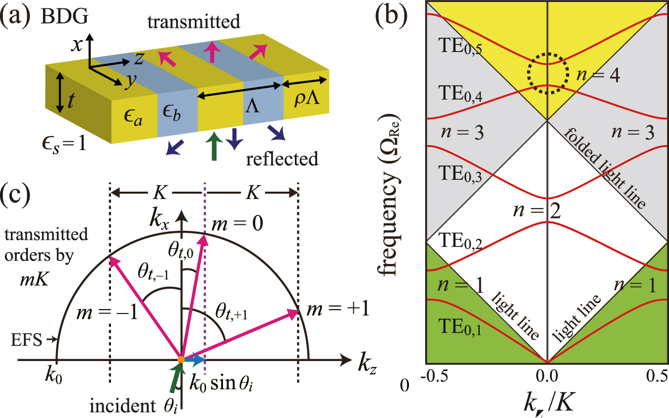
(a) Schematic of a conventional BDG that supports multiple diffraction orders. (b) Dispersion curves for the fundamental TE0 mode; K = 2π/Λ is the magnitude of the grating vector. (c) Diffraction orders according to the conventional diffraction equation near the fourth stopband (black dotted circle).
When a light beam of frequency ΩRe = k 0/K is incident on a BDG at an angle θ i , the waveguide modes in the vicinity of the fourth stopband in the yellow region generate diffracted beams with orders m = −1, 0, and +1. Typically, the directions of the mth-order diffracted light beams can be precisely determined using the conventional diffraction equation:
where θ
r,m
and θ
t,m
represent the angles of the reflected and transmitted beams, respectively, and Δk
z
= k
0 sin θ
i
. As illustrated in Figure 1(c), the diffraction orders can be visualized with the equifrequency surfaces of the surrounding media [34]. Because θ
r,m
= θ
t,m
for a BDG surrounded by a single transparent medium, only the transmitted orders are illustrated. In this conventional scheme, the waveguide mode with k
z
= k
0 sin θ
i
experiences out-of-plane radiation with an additional momentum of mK and a period of Λ. In principle, the periodic dielectric function can be expanded as a Fourier cosine function series
3 Principles of resonant diffraction and FCE metasurfaces
We first identify the dominant Fourier components that cause out-of-plane radiations at the fourth stopband by introducing the new diffraction equation. For periodic photonic structures, the electric field can be generally expressed in the Bloch form [39, 40]. For the guided modes near the fourth stopband that open at the third-order Γ point (k z = 2K in the extended Brillouin zone), the field distribution can be expressed as
where A and B are slowly varying envelopes of the two counterpropagating waves, φ(x) characterizes the mode profile of the unmodulated waveguide, and Δk z = k 0 sin θ i [41–45]. With the consideration that the two counterpropagating waves, P(x, z) = A exp[i(Δk z + 2K)z]φ(x) and N(x, z) = B exp[i(Δk z − 2K)z]φ(x), produce the diffracting wave E rad by superposition of the scattering processes owing to the higher Fourier harmonics ϵ n≥1 cos(nKz), we introduce the new resonant diffraction equation as follows:
where the + and − signs represent the propagating waves P(x, z) and N(x, z), respectively, nK is the magnitude of the grating vector by the nth Fourier harmonic, and v represents the order of the scattering processes. Figure 2 illustrates the resonant diffraction according to Eq. (3) near the fourth stopband. Comparing Eqs. (3) and (1), it is observed that Eq. (1) with m = 0 is equivalent to Eq. (3) with (v, n) = (1, 2) and (2, 1) for both the P and N waves. For a higher diffraction order with m = +1, Eq. (1) is equivalent to Eq. (3) with (v, n) = (1, 1) for the P wave and (v, n) = (1, 3) and (3, 1) for the N wave. Similarly, Eq. (1) with m = −1 is equivalent to Eq. (3) with (v, n) = (1, 3) and (3, 1) for the P wave and (v, n) = (1, 1) for the N wave. As a result, we can conclude that in the region near the fourth stopband beyond the subwavelength limit, the zero-order resonant diffraction is determined by the first and second Fourier harmonic components, whereas higher diffraction orders with m = ±1 are determined by the first and third Fourier harmonic components. Inspired by this analysis using Eq. (3), we introduce and analyze new FCE metasurfaces, namely FCE MS1 and FCE MS2 through rigorous finite element method (FEM) simulations. The FCE MS1 does not possess the first and third Fourier harmonic components in the spatial dielectric function and is expected to realize highly efficient zero-order spectral responses beyond the subwavelength limit. By employing FCE MS2, which does not possess the first, second, and third Fourier harmonic components, we expect to obtain high-Q bound states near the fourth stopband [33].
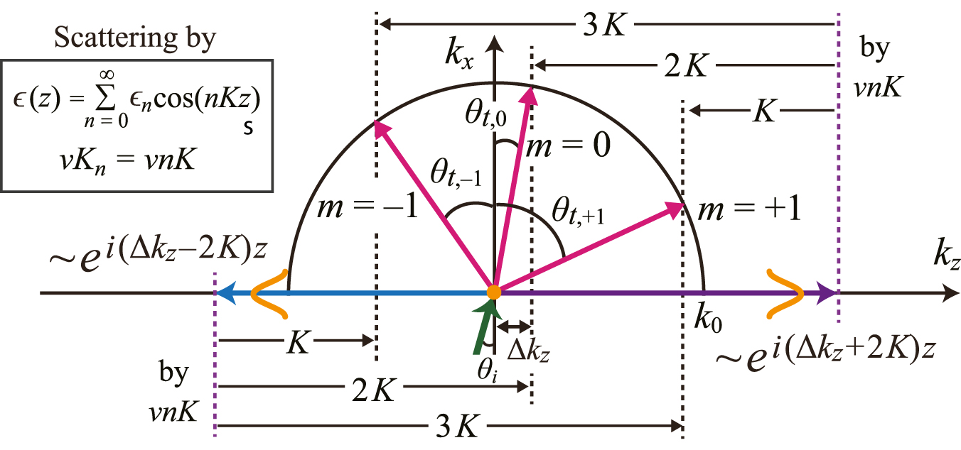
Resonant diffraction by Eq. (3) near the fourth stopband beyond the subwavelength limit.
In Figure 3, we compare the key properties of the conventional BDG with those of the corresponding FCE MS1 and FCE MS2. As shown in Figure 3(a), (e), and (i), while the conventional BDG has simple steplike dielectric functions ϵ BDG = ϵ a and ϵ b when |z| < ρΛ/2 and |z| ≥ ρΛ/2, respectively, FCE MS1 and FCE MS2 have complex dielectric functions ϵ MS1 = ϵ BDG − ϵ 1 cos(Kz) − ϵ 3 cos(3Kz) and ϵ MS2 = ϵ BDG − ϵ 1 cos(Kz) − ϵ 2 cos(2Kz) − ϵ 3 cos(3Kz), respectively. The simulated dispersion relations depicted in Figure 3(b), (f), and (j) shows that the fourth band gaps open at k z = 0 beyond the subwavelength limit (ΩRe > 1) for the conventional BDG and FCE metasurfaces. The dispersion curves for the BDG and FCE metasurfaces seem to be similar; however, noticeable differences are observed among the BDG, MS1, and MS2 from the spatial electric field (E y ) distributions in the insets. In the conventional BDG, both the lower and upper band edge modes with asymmetric (A) and symmetric (S) spatial electric field distributions are radiative out of the grating owing to the higher diffraction orders with m = ±1, as shown in Figure 3(b). We note that protection by the symmetry mismatch is valid only for the zero-order diffraction radiating in the vertical direction. In the FCE MS1 (shown in Figure 3(f)), while the symmetric upper band edge mode is radiative out of the metasurface, the asymmetric lower edge mode becomes the symmetry-protected BIC. This is because there are no higher diffraction orders without the first and third Fourier harmonics. In the FCE MS2 (shown in Figure 3(j)), the symmetric upper and asymmetric lower band edge modes are strongly localized in the metasurface layer because there is no radiative scattering by the higher Fourier harmonics. The effects of the higher Fourier harmonic components are similarly observed by investigating the radiative Q factors, which are plotted in Figure 3(c), (g), and (k). In the BDG, the Bloch modes in both the lower and upper band branches have low Q values (∼103), and no BIC is observed. In the FCE MS1, the BIC in the lower band exhibits a Q factor greater than 108 at the Γ point; however, the Q values decrease rapidly as k z moves away from the Γ point. In the FCE MS2 (shown in Figure 3(k)), the Bloch modes in both the lower and upper band branches become strongly confined BICs with high Q values (∼108) in the computational range of |k z | ≤ 0.07K.
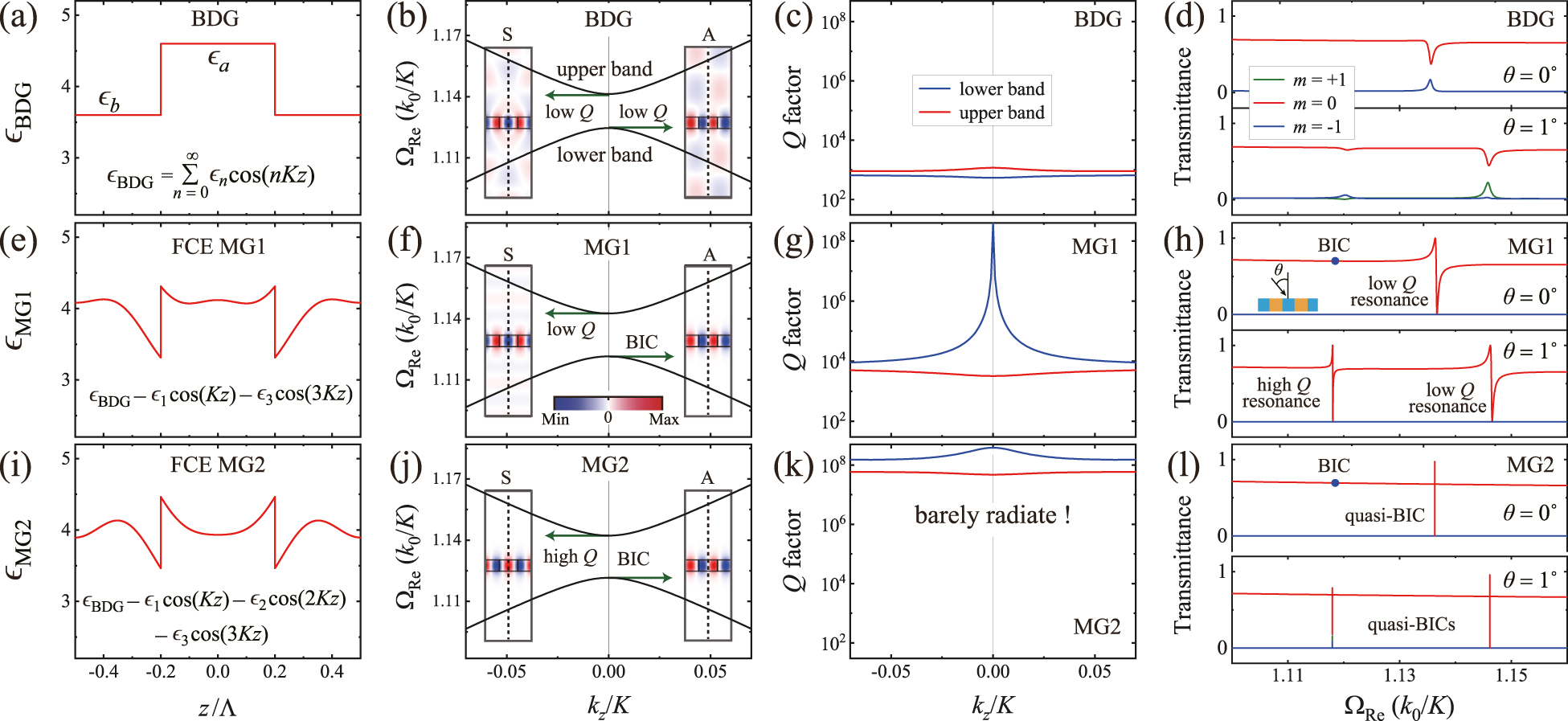
Comparisons between the key properties of the conventional (a)–(d) BDG, (e)–(h) FCE MS1, and (i)–(l) FCE MS2. (a), (c), and (i) depict the dielectric functions with respect to z. (b), (f), and (j) show the FEM-simulated dispersion relations. The blue and red insets illustrate the spatial electric field (E y ) distributions of the band edge modes on the y = 0 plane. The vertical dotted lines represent the mirror planes in the computational cells. (c), (g), and (k) show the calculated radiative Q factors of the lower and upper bands. (d), (h), and (l) show the transmission spectra through the BDG, FCE MS1, and FCE MS2. In the FEM simulations, the following structural parameters were used: ϵ av = 4.00, Δϵ = 1.00, ϵ s = 1.00, t = 0.30Λ, and ρ = 0.40.
Figure 3(d), (h), and (l) illustrates the transmission spectra through the conventional BDG, FCE MS1, and FCE MS2, respectively, for two different incident angles θ = 0° and 1°. The periodic photonic structures exhibit three transmitted diffraction orders: m = −1, 0, and +1. The transmittance curves for m = −1 and +1, shown by blue and green lines, respectively, are the same when θ = 0°; however, they can be distinguished when θ = 1°. As illustrated in Figure 3(d), no diffraction is observed with 100% efficiency for the BDG. However, as illustrated in Figure 3(h), the zero-order transmittance curves (red lines) through FCE MS1 exhibit the ordinary profiles of Fano resonances [46], in which the transmitted diffraction efficiency rapidly varies from 0 to 100% in the vicinities of the resonant frequencies, irrespective of the incident angle θ. At normal incidence with θ = 0°, the zero-order transmittance curve exhibits only the low-Q resonance by the upper band edge mode because the embedded BIC in the lower band edge mode (shown by a blue solid circle in the transmittance curve) does not generate any resonance effect. When θ = 1°, the simulated transmittance curve for m = 0 exhibits low- and high-Q resonances by the upper and lower band modes, respectively. Diffraction orders with m = −1 and +1 exhibit only zero transmittance through the FCE MS1. As illustrated in Figure 3(l), when θ = 0°, the zero-order transmittance curve through the FCE MS2 exhibits a high-Q resonance, in which the diffraction efficiency varies from 0 to 97%, and the BIC is not associated with resonance. When θ = 1°, two quasi-BICs are observed in the transmittance curve for m = 0. In the vicinities of the quasi-BICs by the lower and upper band modes, the zero-order transmission efficiencies vary from 18 to 79% and from 0 to 96%, respectively. In this study, the dielectric components are assumed to be dispersionless and lossless. Even though the real dielectrics are dispersive, we believe that the proposed FCE metasurfaces can be designed to operate within narrow frequency ranges where the dielectric constants are nearly constant. BICs and Fano resonances are caused by the resonant coupling between lateral Bloch modes in the FCE metasurface and outside plane waves. During the resonant coupling process, incident waves inevitably lose their electromagnetic energy due to the intrinsic material loss. Hence, it is reasonable to infer that the FCE metasurfaces with intrinsic material loss can support only quasi-BICs with finite Q factors. The diffraction efficiency of the Fano resonance also decreases. Investigation of the effects of material loss is beyond the scope of the present study and may be the issue of our future work.
We now identify the dominant Fourier components at the sixth stop band open at the fourth-order Γ point (k z = 3K in the extended Brillouin zone). With the electric field distribution E y (x, z) = P(x, y) + N(x, y) + E rad, where P(x, y) = A exp[i(Δk z + 3K)z]φ(x) and N(x, z) = B exp[i(Δk z − 3K)z]φ(x), the resonant diffraction equation can be written as follows:
Figure 4(a) illustrates the resonant diffraction using Eq. (4). We note that Eq. (1) with m = 0 is equivalent to Eq. (4) with (v, n) = (1, 3) and (3, 1) for both the P and N waves. For a diffraction order of m = +1, Eq. (1) is equivalent to Eq. (4) with (v, n) = (1, 2) and (2, 1) for the P wave and (v, n) = (1, 4), (4, 1), and (2, 2) for the N wave. Likewise, Eq. (1) with m = −1 is equivalent to Eq. (4) with (v, n) = (1, 4), (4, 1), and (2, 2) for the P wave and (v, n) = (1, 2) and (2, 1) for the N wave. To summarize, the zero-order resonant diffraction, shown in Figure 4(a), is determined by the first and third Fourier harmonics, whereas the higher diffraction orders with m = ±1 are determined by the first, second, and fourth Fourier harmonics.
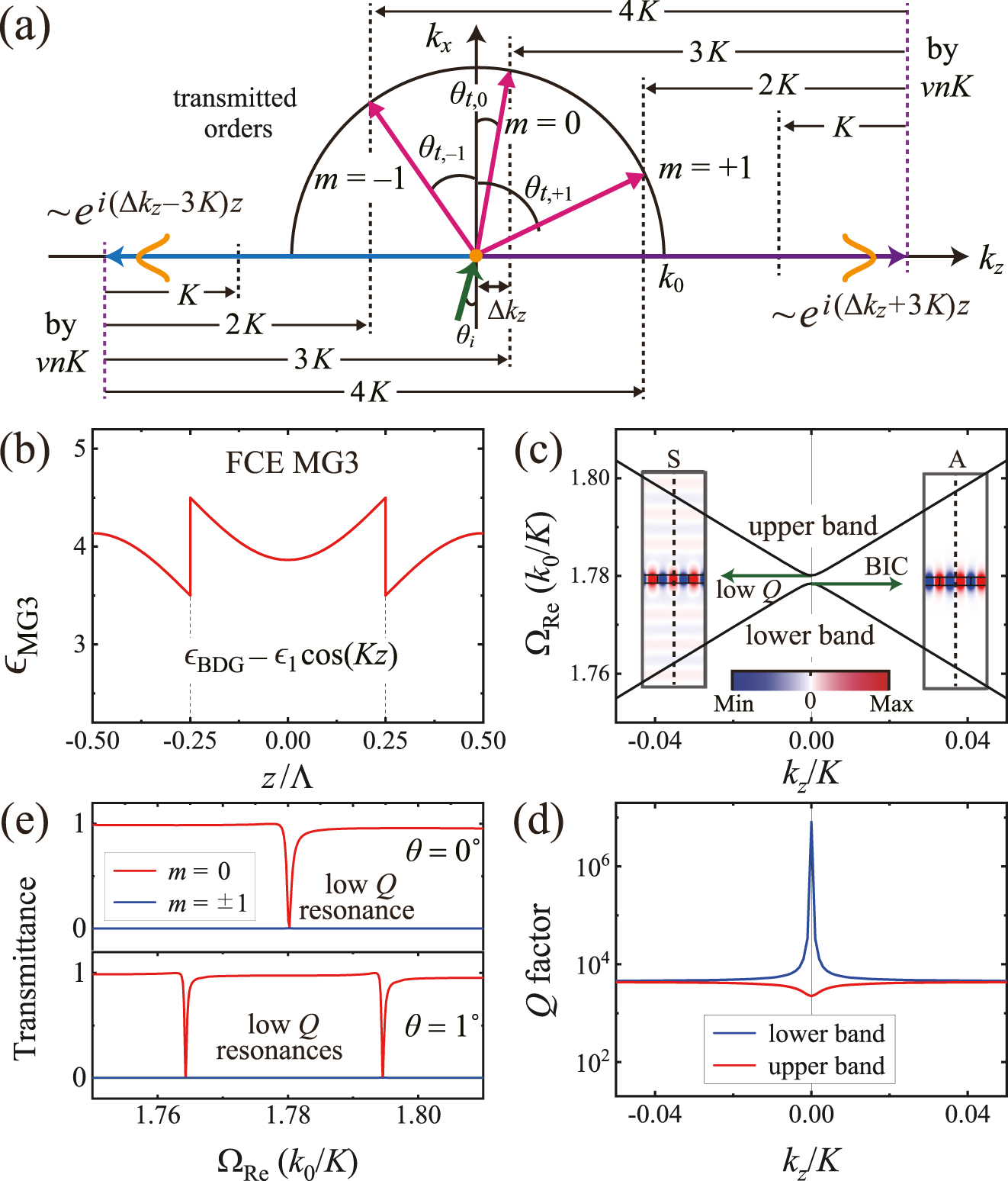
Resonant diffraction near the sixth stop band beyond the subwavelength limit. (a) Diffraction orders by Eq. (4). (b) Spatial dielectric function with respect to z. Simulated (c) dispersion relations, (d) radiative Q factors, and (e) transmission spectra near the sixth stop band of FCE MS3. In the simulations, the following structural parameters were used: ϵ av = 4.00, Δϵ = 1.00, ϵ s = 1.00, t = 0.15Λ, and ρ = 0.50.
Based on the analysis using Eq. (4), we introduce an additional metasurface, FCE MS3, which has the engineered dielectric function ϵ MS3 = ϵ BDG − ϵ 1 cos(Kz), as shown in Figure 4(b). Analysis using Eq. (4) indicates that the higher diffraction orders of m = ±1 can be suppressed by eliminating the first, second, and fourth Fourier components from ϵ BDG. To avoid complex spatial profiles of the dielectric constant, we set the second and fourth Fourier coefficients, ϵ 2 and ϵ 4, to zeros using the lattice parameter ρ = 0.5 instead of eliminating the spatial modulations ϵ 2 cos(2Kz) and ϵ 4 cos(4Kz). The simulated dispersion curves and radiative Q factors, shown in Figure 4(c) and (d), respectively, indicate that the fourth bandgap opens at the fourth-order Γ point. The lower band edge mode with an asymmetric field distribution becomes a BIC, whereas the upper band edge mode with a symmetric field distribution radiates out of the metasurface layer. The spatial electric field distribution of the symmetric edge mode, illustrated in the inset of Figure 4(c), indicates that the out-of-plane radiation occurs only in the zero-order vertical direction because the higher diffraction orders are suppressed by the engineered Fourier harmonic components. The simulated transmittance curves for the FCE MS3 shown in Figure 4(e) demonstrate that irrespective of the incident angle θ, the diffraction orders of m = ±1 exhibit only zero transmittance, whereas the zero-order spectral responses vary from 0 to 1 in the vicinities of the resonance frequencies beyond the subwavelength limit.
Next, we consider the out-of-plane diffraction in the vicinity of the third stopband in the gray region, where two diffraction orders of m = 0 and m = −1 coexist. Using the resonant diffraction equation, given by
and the corresponding phase-matching processes illustrated in Figure 5(a), we conclude the following: in the vicinity of the third stopband, both diffraction orders, m = 0 and m = −1, are determined by the first and second Fourier harmonic components. Thus, the diffraction order of m = −1 cannot be selectively suppressed through the engineering of the Fourier harmonic components. However, high-Q BICs can be achieved by utilizing the engineered dielectric function ϵ MG4 = ϵ BDG − ϵ 1 cos(Kz) − ϵ 2 cos(2Kz) or ϵ BDG − ϵ 1 cos(Kz) with ρ = 0.5. As an additional example of the engineering of Fourier harmonic components, we introduce a metasurface, FCE MS4, that exhibits a high-Q BIC at one edge of the third stopband. The dielectric function of FCE MS4 was set to ϵ MG4 = ϵ BDG − μ × ϵ 1 cos(Kz), where the coefficient μ is introduced to control the strength of the first Fourier harmonic component. By varying the value of μ, as shown in Figure 5(b), there exist two critical values μ 1 = 0.708 and μ 2 = 1.303, where out-of-plane radiations, owing to the first and second Fourier harmonic components, eliminate each other via destructive interference. When μ = μ 1 (μ = μ 2), the BIC with an asymmetric (symmetric) field distribution is observed in the lower (upper) band edge. There are two critical values, μ 1 < 1 and μ 2 > 1, because the contribution of the first Fourier component increases as the value of μ increases or decreases from 1. We consider that the BIC is observed at one of the band edges because the condition for complete destructive interference strongly depends on the eigenfrequency of the band edge mode. Figure 5(c) shows that the band edge frequencies vary as μ increases.
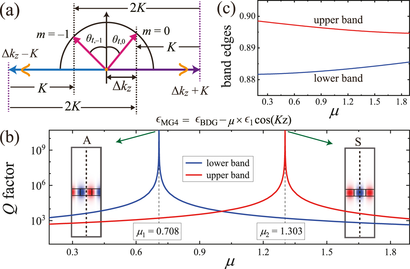
Resonant diffraction in the vicinity of the third stopband beyond the subwavelength limit. (a) Diffraction orders by Eq. (5). Simulated (b) radiative Q factors and (c) eigenfrequencies of the two band-edge modes as a function μ. In addition to the engineered dielectric function, the structural parameters were the same as those in Figure 2.
In this study, we performed analytical and numerical investigations to control light diffraction in the vicinities of higher stopbands. The proposed FCE metasurfaces may be practically implemented by utilizing the metamaterial concept [47, 48], which can mimic the required dielectric constant profile using a series of discrete step functions [33, 49]. Owing to the complex spatial variations, it is challenging to implement FCE metasurfaces at optical wavelengths. However, current microfabrication technology is sufficient to demonstrate the effects of engineered dielectric functions in the microwave range. To visualize this, as shown in Figure 6(a), we consider an alumina-air metasurface consisting of air slits, S j , in an alumina slab (ϵ al = 9.7 at 10 GHz). Twenty air slits are appropriately located in the unit cell of size Λ, such that the effective dielectric function of the alumina-air metasurface mimics that of the FCE MG2, as illustrated in Figure 6(b). Even though the effective dielectric function of the alumina-air metasurface varies in discrete steps, not only the dispersion curves of the alumina-air metasurface in Figure 6(c) are nearly the same as those of the FCE MG2 in Figure 3(j) but also the radiative Q factors in the alumina-air metasurface in Figure 6(d) are comparable to the high Q values in the FCE MG2 in Figure 3(k). The radiative Q factors in the alumina-air metasurface are approximately 104 times larger than those in the conventional BDG in Figure 3(c).
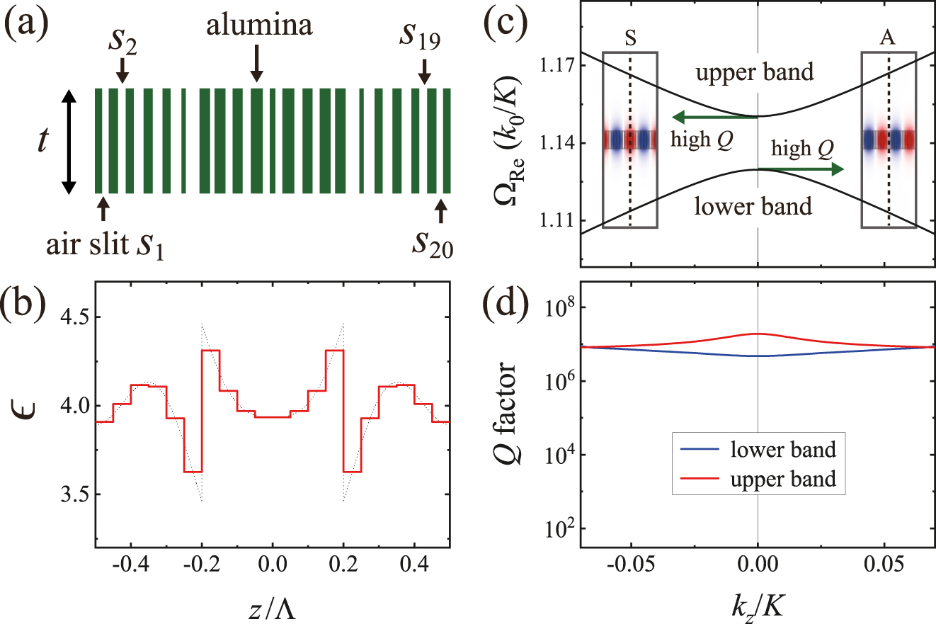
(a) Schematic of an alumina-air metasurface with t = 0.30Λ. (b) The effective dielectric constant of the alumina-air metasurface in the computational unit cell of size Λ. The dotted line represents the dielectric constant of the FCE MG2. Simulated dispersion relations (c) and radiative Q factors (d) near the fourth stopband of the alumina-air metasurface.
4 Conclusions
In conclusion, we introduced and analyzed novel FCE metasurfaces that operate in the vicinities of higher stopbands open in the nonsubwavelength regime. In principle, resonant diffraction phenomena are governed by the superposition of scattering processes, owing to higher Fourier harmonic components of periodic modulations in the lattice parameters. However, FCE metasurfaces are enabled because only some of Fourier harmonic components are dominant at band edges with Bragg conditions. We revealed that both BICs and highly efficient Fano resonances could be achieved beyond the subwavelength limit by suppressing the unwanted diffraction orders via engineered Fourier harmonic components. To engineer the spatial dielectric functions, we presented new principles of light diffraction that enable the identification of the dominant Fourier harmonic components causing out-of-plane radiations at the higher stopbands. The proposed metasurface concepts can help control the unwanted diffraction orders and extend the BICs and Fano resonances to higher stopbands; thus, they provide new opportunities to manipulate the electromagnetic waves in artificial periodic structures.
Funding source: Ministry of Education
Award Identifier / Grant number: No. 2020R1I1A1A01073945
Funding source: ICT
Award Identifier / Grant number: No. 2020R1F1A1050227
Funding source: Ministry of Science
Funding source: Gwangju Institute of Science and Technology Research Institute
Funding source: National Research Foundation of Korea
-
Author contribution: All the authors have accepted responsibility for the entire content of this submitted manuscript and approved submission.
-
Research funding: This research was supported by a grant from the National Research Foundation of Korea, funded by the Ministry of Education (No. 2020R1I1A1A01073945) and Ministry of Science and ICT (No. 2020R1F1A1050227), along with the Gwangju Institute of Science and Technology Research Institute in 2021.
-
Conflict of interest statement: The authors declare no conflicts of interest regarding this article.
References
[1] T. Young, “The bakerian lecture: on the theory of light and colours,” Phil. Trans. Roy. Soc. Lond., vol. 92, pp. 12–48, 1802. https://doi.org/10.1098/rstl.1802.0004.Search in Google Scholar
[2] J. Fraunhofer, “Kurtzer Bericht von the Resultaten neuerer Versuche über die Gesetze des Lichtes, und die Theorie derselbem,” Ann. Phys., vol. 74, pp. 337–378, 1823. https://doi.org/10.1002/andp.18230740802.Search in Google Scholar
[3] N. Bonod and J. Neauport, “Diffraction gratings: from principles to applications in high-intensity lasers,” Adv. Opt Photon, vol. 8, p. 1, 2016. https://doi.org/10.1364/aop.8.000156.Search in Google Scholar
[4] R. W. Wood, “On the remarkable case of uneven distribution of a light in a diffractived grating spectrum,” Philos. Mag. A, vol. 4, pp. 396–402, 1902. https://doi.org/10.1080/14786440209462857.Search in Google Scholar
[5] B. Zhen, C. W. Hsu, L. Lu, A. D. Stone, and M. Soljačić, “Topological nature of optical bound states in the continuum,” Phys. Rev. Lett., vol. 113, no. 25, p. 257401, 2014. https://doi.org/10.1103/physrevlett.113.257401.Search in Google Scholar
[6] X. Gao, C. W. Hsu, B. Zhen, et al.., “Formation mechanism of guided resonances and bound states in the continuum in photonic crystal slabs,” Sci. Rep, vol. 6, p. 31908, 2016. https://doi.org/10.1038/srep31908.Search in Google Scholar PubMed PubMed Central
[7] L. Ni, Z. Wang, C. Peng, and Z. Li, “Tunable optical bound states in the continuum beyond in-plane symmetry protection,” Phys. Rev. B, vol. 94, p. 245148, 2016. https://doi.org/10.1103/physrevb.94.245148.Search in Google Scholar
[8] S. D. Krasikov, A. A. Bogdanov, and I. V. Iorsh, “Nonlinear bound states in the continuum of a one-dimensional photonic crystal slab,” Phys. Rev. B, vol. 97, no. 22, p. 224309, 2018. https://doi.org/10.1103/physrevb.97.224309.Search in Google Scholar
[9] E. N. Bulgakov and D. N. Maksimov, “Avoided crossings and bound states in the continuum in low-contrast dielectric gratings,” Phys. Rev. A, vol. 98, p. 053840, 2018. https://doi.org/10.1103/physreva.98.053840.Search in Google Scholar
[10] K. Koshelev, S. Lepeshov, M. Liu, A. Bogdanov, and Y. Kivshar, “Asymmetric metasurfaces with high-Q resonances governed by bound states in the continuum,” Phys. Rev. Lett., vol. 121, p. 193903, 2018. https://doi.org/10.1103/physrevlett.121.193903.Search in Google Scholar
[11] S.-G. Lee, S. H. Kim, and C. S. Kee, “Bound states in the continuum (BIC) accompanied by avoided crossings in leaky-mode photonic lattices,” Nanophotonics, vol. 9, no. 14, pp. 4374–4380, 2020. https://doi.org/10.1515/nanoph-2020-0346.Search in Google Scholar
[12] A. I. Ovcharenko, C. Blanchard, J.-P. Hugonin, and C. Sauvan, “Bound states in the continuum in symmetric and asymmetric photonic crystal slabs,” Phys. Rev. B, vol. 101, no. 15, p. 155303, 2020. https://doi.org/10.1103/physrevb.101.155303.Search in Google Scholar
[13] D. N. Maksimov, A. A. Bogdanov, and E. N. Bulgakov, “Optical bistability with bound states in the continuum in dielectric gratings,” Phys. Rev. A, vol. 102, p. 033511, 2020. https://doi.org/10.1103/physreva.102.033511.Search in Google Scholar
[14] X. Zhao, C. Chen, K. Kaj, et al.., “Terahertz investigation of bound states in the continuum of metallic metasurfaces,” Optica, vol. 7, no. 11, pp. 1548–1554, 2020. https://doi.org/10.1364/optica.404754.Search in Google Scholar
[15] A. Cerjan, M. Jürgensen, W. A. Benalcazar, S. Mukherjee, and M. C. Rechtsman, “Observation of a higher-order topological bound state in the continuum,” Phys. Rev. Lett., vol. 125, no. 125, p. 213901, 2020. https://doi.org/10.1103/PhysRevLett.125.213901.Search in Google Scholar PubMed
[16] A. Overvig, N. Yu, and A. Alù, “Chiral quasi-bound states in the continuum,” Phys. Rev. Lett., vol. 126, p. 073001, 2021. https://doi.org/10.1103/PhysRevLett.126.073001.Search in Google Scholar PubMed
[17] M. Kang, S. Zhang, M. Xiao, and H. Xu, “Merging bound states in the continuum at off-high symmetry points,” Phys. Rev. Lett., vol. 126, p. 117402, 2021. https://doi.org/10.1103/physrevlett.126.117402.Search in Google Scholar
[18] K. Koshelev, S. Kruk, E. Melik-Gaykazyan, et al.., “Subwavelength dielectric resonators for nonlinear nanophotonics,” Science, vol. 367, pp. 288–292, 2020. https://doi.org/10.1126/science.aaz3985.Search in Google Scholar PubMed
[19] M.-S. Hwang, H.-C. Lee, K.-H. Kim, et al.., “Ultralow-threshold laser using super-bound states in the continuum,” Nat. Commun., vol. 12, p. 4135, 2021. https://doi.org/10.1038/s41467-021-24502-0.Search in Google Scholar PubMed PubMed Central
[20] M. V. Gorkunov, A. A. Antonov, V. R. Tuz, A. S. Kupriianov, and Y. S. Kivshar, “Bound states in the continuum underpin near-lossless maximum chirality in dielectric metasurfaces,” Adv. Optical Mater., p. 2100797, 2021, https://doi.org/10.1002/adom.202100797.Search in Google Scholar
[21] M.-S. Hwang, H.-R. Kim, Y. K-Jeong, H.-G. Park, and Y. Kivshar, “Novel non-plasmonic nanolasers empowered by topology and interference effects,” Nanophotonics, p. 20210265, 2021, https://doi.org/10.1515/nanoph-2021-0265.Search in Google Scholar
[22] Y. H. Ko and R. Magnusson, “Wideband dielectric metamaterial reflectors: mie scattering or leaky Bloch mode resonance?” Optica, vol. 5, pp. 289–294, 2018. https://doi.org/10.1364/optica.5.000289.Search in Google Scholar
[23] R. Magnusson and M. Shokooh-Saremi, “Physical basis for wideband resonant reflectors,” Opt. Express, vol. 16, no. 5, pp. 3456–3462, 2008. https://doi.org/10.1364/oe.16.003456.Search in Google Scholar PubMed
[24] C. W. Hsu, B. Zhen, A. D. Stone, J. D. Joannopoulos, and M. Soljačić, “Bound states in the continuum,” Nat. Rev. Mater, vol. 1, pp. 1–13, 2016. https://doi.org/10.1038/natrevmats.2016.48.Search in Google Scholar
[25] F. Brückner, D. Friedrich, T. Clausnitzer, et al.., “Realization of a monolithic high-reflectivity cavity mirror from a single silicon crystal,” Phys. Rev. Lett., vol. 104, no. 16, p. 163903, 2010. https://doi.org/10.1103/physrevlett.104.163903.Search in Google Scholar PubMed
[26] C. J. Chang-Hasnain and W. Yang, “High-contrast gratings for integrated optoelectronics,” Adv. Opt. Photon., vol. 4, pp. 379–440, 2012. https://doi.org/10.1364/aop.4.000379.Search in Google Scholar
[27] R. Magnusson, “Wideband reflectors with zero-contrast gratings,” Opt. Lett., vol. 39, pp. 4337–4340, 2014. https://doi.org/10.1364/ol.39.004337.Search in Google Scholar
[28] J. W. Yoon, K. J. Lee, and R. Magnusson, “Ultra-sparse dielectric nanowire grids as wideband reflectors and polarizers,” Opt. Express, vol. 23, pp. 28849–28856, 2015. https://doi.org/10.1364/oe.23.028849.Search in Google Scholar
[29] M. Niraula, J. W. Yoon, and R. Magnusson, “Single-layer optical bandpass filter technology,” Opt. Lett., vol. 40, pp. 5062–5065, 2015. https://doi.org/10.1364/ol.40.005062.Search in Google Scholar PubMed
[30] G. Quaranta, G. Basset, O. J. F. Martin, and B. Gallinet, “Recent advances in resonant waveguide gratings,” Laser Photon. Rev., vol. 12, p. 1800017, 2018. https://doi.org/10.1002/lpor.201800017.Search in Google Scholar
[31] H. Hemmati, P. Bootpakdeetam, and R. Magnusson, “Metamaterial polarizer providing principally unlimited extinction,” Opt. Lett., vol. 44, pp. 5630–5633, 2019. https://doi.org/10.1364/ol.44.005630.Search in Google Scholar PubMed
[32] X. Yin, J. Jin, M. Soljačić, C. Peng, and B. Zhen, “Observation of topologically enabled unidirectional guided resonances,” Nature, vol. 580, pp. 467–471, 2020. https://doi.org/10.1038/s41586-020-2181-4.Search in Google Scholar PubMed
[33] S.-G. Lee, S. H. Kim, and C. S. Kee, “Metasurfaces with bound states in the continuum enabled by eliminating first fourier harmonic component in lattice parameters,” Phys. Rev. Lett., vol. 126, no. 1, p. 013601, 2021. https://doi.org/10.1103/PhysRevLett.126.013601.Search in Google Scholar PubMed
[34] M. Notomi, “Theory of light propagation in strongly modulated photonic crystals: refractionlike behavior in the vicinity of the photonic band gap,” Phys. Rev. B, vol. 62, no. 16, pp. 10696–10705, 2000. https://doi.org/10.1103/physrevb.62.10696.Search in Google Scholar
[35] S.-G. Lee and R. Magnusson, “Band flips and bound-state transitions in leaky-mode photonic lattices,” Phys. Rev. B, vol. 99, no. 4, p. 045304, 2019. https://doi.org/10.1103/physrevb.99.045304.Search in Google Scholar
[36] S.-G. Lee and R. Magnusson, “Band dynamics of leaky-mode photonic lattices,” Opt. Express, vol. 27, no. 13, pp. 18180–18189, 2019. https://doi.org/10.1364/oe.27.018180.Search in Google Scholar PubMed
[37] S.-G. Lee, S. H. Kim, C. S. Kee, and R. Magnusson, “Polarization-differentiated band dynamics of resonant leaky modes at the Γ lattice point,” Opt. Express, vol. 28, no. 26, pp. 39453–39462, 2020. https://doi.org/10.1364/oe.413357.Search in Google Scholar
[38] S.-G. Lee, S. H. Kim, and C. S. Kee, “Band dynamics accompanied by bound states in the continuum at the third-order Γ point in leaky-mode photonic lattices,” Photon. Res., vol. 9, no. 6, pp. 1109–1116, 2021. https://doi.org/10.1364/prj.417150.Search in Google Scholar
[39] J. D. Joannopoulos, R. D. Meade, and J. N. Winn, Photonic Crystals: Molding the Flow of Light, New Jersey, Princeton University, 1995.Search in Google Scholar
[40] A. Yariv and P. Yeh, Optical Waves in Crystals, New York, Wiley, 1984.Search in Google Scholar
[41] R. F. Kazarinov and C. H. Henry, “Second-order distributed feedback lasers with mode selection provided by first-order radiation loss,” IEEE J. Quant. Electron., vol. 21, pp. 144–150, 1985. https://doi.org/10.1109/jqe.1985.1072627.Search in Google Scholar
[42] D. Rosenblatt, A. Sharon, and A. A. Friesem, “Resonant grating waveguide structure,” IEEE J. Quant. Electron., vol. 33, pp. 2038–2059, 1997. https://doi.org/10.1109/3.641320.Search in Google Scholar
[43] Y. Ding and R. Magnusson, “Band gaps and leaky-wave effects in resonant photonic-crystal waveguides,” Opt. Express, vol. 15, no. 2, pp. 680–694, 2007. https://doi.org/10.1364/oe.15.000680.Search in Google Scholar PubMed
[44] C. Peng, Y. Liang, K. Sakai, S. Iwahashi, and S. Noda, “Coupled-wave analysis for photonic-crystal surface-emitting lasers on air-holes with arbitrary sidewalls,” Opt. Express, vol. 19, pp. 24672–24686, 2011. https://doi.org/10.1364/oe.19.024672.Search in Google Scholar PubMed
[45] Y. Yang, C. Peng, and Z. Li, “Semi-analytical approach for guided mode resonance in high-index-contrast photonic crystal slab: TE polarization,” Opt. Express, vol. 21, pp. 20588–20600, 2013. https://doi.org/10.1364/oe.21.020588.Search in Google Scholar PubMed
[46] A. E. Miroshnichenko, S. Flach, and Y. S. Kivshar, “Fano resonances in nanoscale structures,” Rev. Mod. Phys., vol. 82, no. 3, pp. 2257–2298, 2010. https://doi.org/10.1103/revmodphys.82.2257.Search in Google Scholar
[47] D. Schurig, J. Mock, B. Justice, et al.., “Metamaterial electromagnetic cloak at microwave frequencies,” Science, vol. 314, p. 977, 2006. https://doi.org/10.1126/science.1133628.Search in Google Scholar PubMed
[48] H. F. Ma and T. J. Cui, “Three-dimensional broadband ground-plane cloak made of metamaterials,” Nat. Commun., vol. 1, no. 3, p. 21, 2010. https://doi.org/10.1038/ncomms1023.Search in Google Scholar PubMed PubMed Central
[49] C. W. Haggans, L. Li, and R. K. Kostuk, “Effective-medium theory of zeroth-order lamellar gratings in conical mountings,” J. Opt. Soc. Am. A, vol. 10, pp. 2217–2225, 1993. https://doi.org/10.1364/josaa.10.002217.Search in Google Scholar
© 2021 Sun-Goo Lee et al., published by De Gruyter, Berlin/Boston
This work is licensed under the Creative Commons Attribution 4.0 International License.
Articles in the same Issue
- Frontmatter
- Review
- Femtosecond laser micromachining for integrated quantum photonics
- Research Article
- Synthetic plasmonic lattice formation through invariant frequency comb excitation in graphene structures
- Nearly total optical transmission of linearly polarized light through transparent electrode composed of GaSb monolithic high-contrast grating integrated with gold
- Super-regular femtosecond laser nanolithography based on dual-interface plasmons coupling
- Inverse design of grating couplers using the policy gradient method from reinforcement learning
- Exfoliated Bi2Te3 nanoparticle suspensions and films: morphological and nonlinear optical characterization
- Experimental demonstration of broadband negative refraction at visible frequencies by critical layer thickness analysis in a vertical hyperbolic metamaterial
- Sensitive THz sensing based on Fano resonance in all-polymeric Bloch surface wave structure
- Photonic crystal nanobeam cavities with lateral fins
- Spectral tuning of diamond photonic crystal slabs by deposition of a thin layer with silicon vacancy centers
- Tailoring of plasmonic functionalized metastructures to enhance local heating release
- Fourier-component engineering to control light diffraction beyond subwavelength limit