Linear-polarized terahertz isolator by breaking the gyro-mirror symmetry in cascaded magneto-optical metagrating
-
Zhiyu Tan
 ,
Fei Fan
,
Fei Fan
 ,
Dan Zhao
,
Dan Zhao

Abstract
To realize nonreciprocal transmission, it is necessary to break the time-reversal symmetry of the transmission system, but it is very challenging to keep the linear polarized (LP) input and output unchanged in the free space transmission system. Magnetized semiconductor InSb can realize terahertz (THz) nonreciprocal transmission for the two conjugated photonic spin states, but it cannot realize efficient one-way transmission of LP state due to gyro-mirror symmetry. In this work, by introducing a pair of orthogonal uniaxial anisotropies from the meta-gratings on both sides of InSb, both the gyro-mirror and time-reversal symmetries are broken for the LP state, thus making this cascaded grating–InSb–grating structure serves as a high-performance isolator for the LP light. The experiment results indicate isolation of 50 dB at 0.4 THz for the same LP input and output under a weak biased magnetic field of 0.17 T. Moreover, we further illustrate the factors affecting the isolation bandwidth of the device, also demonstrated another broadband structure with the 10 dB isolation bandwidth from 0.2–0.7 THz, and the relative bandwidth achieves 110%. The mechanisms of THz nonreciprocal transmission and polarization manipulation proposed in this work will contribute to the development of efficient THz magneto-optical devices.
1 Introduction
Isolators and circulators are nonreciprocal one-way transmission devices, in which the forward electromagnetic wave propagates with low insertion losses, but the backward wave cannot transmit due to a very large attenuation [1], [2], [3], which plays some great important roles in the protection of source and detector, impedance matching, noise-canceling, and decoupling [4, 5]. Terahertz (THz) technology involves the electromagnetic band located in the 0.1–10 THz frequency range, which has great potentials in new-generation communication, radar, imaging, and sensing [6], [7], [8], [9]. However, due to the lack of feasible, broadband, and low-loss THz nonreciprocal transmission devices, THz echoes of the reflection and scattering from system components limits the performance of these THz systems. Especially, it threatens the safety of high-power THz source [10], [11], [12] and high-sensitive detection systems [13, 14], which is an essential component in these booming systems.
THz magneto-optical (MO) materials [15], [16], [17], [18], [19] provide a fundamental way of developing nonreciprocal devices. It requires significant MO effects in the THz regime operating under a relatively weak external magnetic field (MF) and small absorption loss for THz waves; however, the materials which meet the above conditions are very rare in the THz regime. For example, Shalaby et al. [20] presented the first THz MO isolator based on a bulk permanent magnet but with a very large loss and low isolation. Recently, the narrow bandgap semiconductor InSb [21], [22], [23], [24], [25] has been received great attention due to its intriguing gyroelectric MO properties in the THz band, whose cyclotron resonance band is located in the THz band under a weak external MF. Different from the THz spintronic devices controlled by the polarization state of femtosecond laser [11, 12], the polarization state of THz wave passing through InSb can be regulated by the direction and value of the external MF. Li et al. [23] experimentally verified the transverse MO effect of InSb, and Mu et al. [24] studied the Faraday MO effect of InSb in a longitudinal MF configuration in the experiment, and combined the InSb with artificial microstructure, realizing a linear polarization conversion with >70% MO modulation depth by the weak MF. InSb also has the potentials in designing isolators. For instance, in 2018, Lin et al. [25] proposed a reflective THz isolator with transverse MO effect of InSb, this one-way isolator achieves 35 dB isolation with 6.2 dB insertion loss for a p-wave polarization. However, it has only a narrow bandwidth and strict incident angle. The unique properties of InSb may provide more effective applications in THz nonreciprocal devices.
MO material introduced into the artificial microstructure, such as magnetic photonic crystal [26, 27], magneto-plasmonics [28], [29], [30], [31], and MO metasurfaces [32], [33], [34], may significantly enhance the MO effect and provide singular electromagnetic transmission characteristics. In 2011, Belotelov et al. [29] demonstrated that the MO effect can be enhanced by combining the MO material with the microstructure. Wang et al. [26] constructed a nonzero Chen number in photonic crystals by using the gyromagnetic properties of YIG and first experimentally observed topological boundary states with the nonreciprocal one-way transmission in the microwave regime. In 2016, Tamagnone et al. [35] reported a THz isolator based on a multilayer stacked graphene under a strong biased magnetic field (MF) of 7 T, which exhibits the isolation of about 20 dB but insertion loss of 7.5 dB at 2.9 THz. THz MO microstructure devices provide new opportunities for the development of THz nonreciprocal transmission mechanisms and devices. THz MO microstructure provides new opportunities for the development of THz nonreciprocal transmission mechanisms.
In this paper, our goal is to achieve efficient THz isolation for the linear polarized (LP) waves without changing the polarization state, that is, the forward output wave is still an LP wave with the same polarization angle but the backward wave is forbidden to be output. To achieve this purpose, we first theoretically analyzed the nonreciprocity of the two conjugated photonic spin eigenstates in longitudinally magnetized InSb, finding that no nonreciprocity for LP state without breaking the gyro-mirror symmetry. By introducing a pair of orthogonal uniaxial anisotropies from the meta-gratings on the two sides of InSb, both the gyro-mirror and time-reversal symmetries are broken for the LP state, thus making this cascaded grating–InSb–grating structure serves as a high-performance isolator for the LP light. The above mechanisms of THz one-way transmission and polarization manipulation have been confirmed by both theory and experiments, and a further broadband result has also been demonstrated.
2 Results and discussions
2.1 Theoretical analysis
When the external MF is applied along the z-axis, the InSb shows a strong gyrotropy property. If a light propagating through the InSb also along the z-axis with Faraday configuration, Maxwell’s wave equation can be written as [17, 24]:
The detailed model of ε 1 and ε 2 above can be seen in Part 1 of Supplementary Information. Therefore, two eigen photonic spin states can be solved from Eq. (1):
Here, the first solution E y = −iE x is the counter-clockwise (CCW) state, and the second one E y = iE x is the clockwise (CW) state. The CCW state also means the forward left-handed circularly polarized light (LCP+) or backward right-handed circularly polarized light (RCP−), meanwhile, the CW state denotes the RCP+ or LCP−. According to Eq. (3), we can theoretically calculate the transmittance of CW state through InSb as follows [24]:
where d = 300 μm is the thickness of the InSb layer, T CCW has the same form as the ε CCW replaces the ε CW. The detailed results can be seen in Part 1 of Supplementary Information. Since ε CW ≠ ε CCW in the same biased MF, so the time-reversal symmetry is broken to realize a nonreciprocal transmission for CW or CCW light. Moreover, when the direction of the MF or the propagating direction is inversed, ε CW+(or CCW+) = ε CCW−(or CW−) in the two reversed MFs, indicating a gyro-mirror symmetry for these two conjugated spin states with the positive and negative MF. It also shows that changing the MF direction is equivalent to changing the propagating direction in this work.
However, if an LP wave is incident into the InSb as shown in Figure 1(a), it can be decomposed into two conjugated spin states in the same phase. The transmission matrix for the LP state incident into the InSb on the x–y vector basis can be written as:
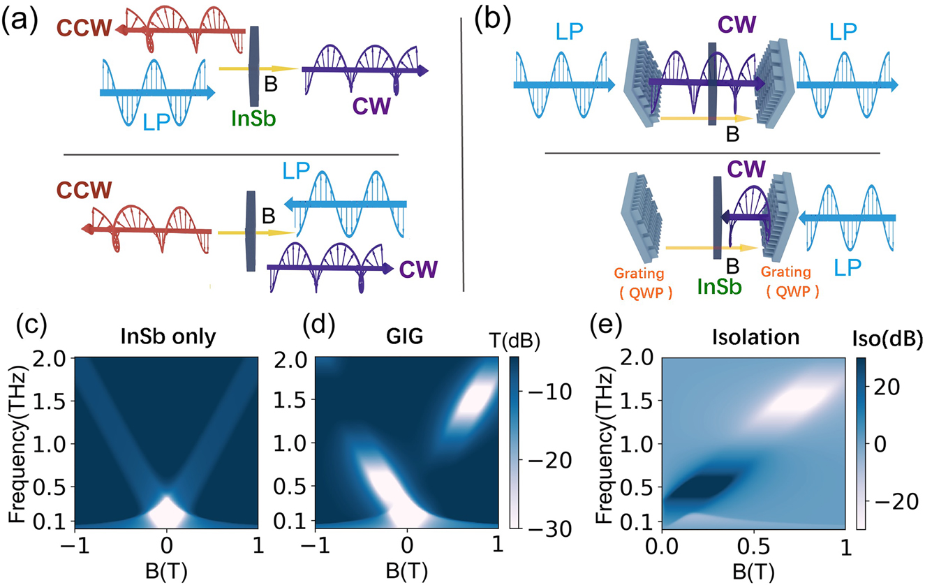
Schematic diagram of THz nonreciprocal one-way transmission based on InSb: the forward and backward LP waves incident into (a) the longitudinally magnetized InSb and (b) the InSb sandwiched in between two orthogonal meta-gratings. The theoretically calculated transmittance map as a function of frequency and the MF for the LP incidence of (c) the bare InSb and (d) GIG structure. (e) The calculated isolation for the LP incidence of GIG structure. In all the calculations, the carrier density of InSb is set to 4 × 1014 cm−3 as the temperature is 80 K.
According to Eqs. (3) and (4), we calculate the transmittance map of LP incidence for the single InSb as shown in Figure 1(c), and the white area is an opaque band in the figure. When B = 0 T, there is a cutting-off frequency around 0.4 THz that the transmittance is less than −30 dB. With the increase of the MFs, the forward wave only transmits CW wave, and the reflected wave only permits CCW wave in the cyclotron resonance frequency band. Figure 1(c) is mirror-symmetric for B = 0. Therefore, as shown in Figure 1(a), when the LP propagates forward through the InSb, the CW light transmits T CW+ ≠ 0, and the CCW is reflected, T CCW+ = 0. When the LP propagates backward through the InSb (the MF direction is still unchanged), the CCW light transmits T CCW− ≠ 0, and the CW is reflected T CW+ = 0. Due to the gyro-mirror symmetry of the InSb, the transmitted waves T CW+ = T CCW− in the above two cases, so T Xout is a reciprocal component with the positive and negative MF (T Xout(B) = T Xout(−B)), half of the LP energy cannot transmit and the polarization becomes one chiral spin state. Therefore, the LP state could not be well isolated by the single InSb crystal.
Since our goal is to achieve efficient isolation for the LP waves without changing the polarization state, it is necessary to introduce a dielectric asymmetry to break the gyro-mirror symmetry while maintaining the nonreciprocity of InSb. Here, we consider utilizing the subwavelength dielectric meta-grating structure with artificial uniaxial anisotropy to introduce the dielectric asymmetry into this nonreciprocal transmission system. As shown in Figure 1(b), a couple of meta-gratings are placed before and after the InSb, forming a cascaded grating–InSb–grating (GIG) structure, where the grating direction of two gratings are orthogonal to each other and 45° to the incident LP direction. In this case, the transmission matrix of the whole system can be written as:
where δ is the phase difference between the x- and y-polarized LP state brought by the meta-grating. For the sake of simplicity, we assume the meta-grating has the linear dispersion as δ = 0.5πf THz−1 where f is the frequency of the wave in the theoretical analysis. According to Eqs. (3) and (5), we calculate the transmittance map of LP incidence for the GIG structure as shown in Figure 1(d). Unlike Figure 1(c), Figure 1(d) is no longer mirror-symmetric for B = 0, and the isolation can be also calculated as follows:
where T(B) and T(−B) are the intensity transmission for the positive MF and negative MF (i.e. equivalent to the forward and backward transmission), respectively. Figure 1(e) shows the isolation map as the frequencies and MFs corresponding to the dark blue and white regions can realize efficient one-way transmission.
In special, when this meta-grating works as a perfect quarter wave-plate (QWP) (δ = 0.5π), the transmission matrix can be simplified as:
Thus, the output wave only depends on the T CW and has one-way transmission property since the T CW is nonreciprocal as discussed above. Moreover, there is no y-component output, which means the output wave is a pure x-LP, so the frequency points that satisfy Eq. (7) can be defined as the perfect isolation case. Figure 1(b) intuitively shows the working principle of the device: when the x-LP propagates forward through the GIG structure, after passing through the first grating, the CW wave is output; then, the CW wave can pass through the magnetized InSb within the cyclotron resonance band; finally, the CW wave is transformed into x-LP wave after passing through the second grating with orthogonal orientation. When the x-LP propagates backward through the GIG structure, the CW wave is still converted, but this backward CW wave cannot pass through the InSb. In this way, the perfect one-way isolation is achieved in theory, while keeping the input–output LP unchanged. Therefore, the efficient one-way isolation band occurs in the overlapping frequency band between the cyclotron resonance of InSb and circular polarization conversion of the meta-gratings.
2.2 Experimental results
Based on the above analysis, we designed and fabricated an MO meta-grating with GIG structure as shown in Figure 2(a). Our InSb single crystal wafer was purchased from Klamar-Reagent Corporation, which was prepared by the liquid phase epitaxial method. The InSb wafer is single-side polished, 300 μm in thickness, 〈111〉 orientation, n-doped with the intrinsic carrier concentration of 4 × 1014 cm−3 and the mobility of 4 × 105 cm2 V−1·s−1 at 80 K. Two Si meta-gratings with orthogonal grating orientations were fabricated on both sides of the InSb. The high resistivity Si wafer was tightly bonded to the InSb crystal. The Si was thinned by the plasma etching, and then the Si grating structures on the InSb substrate were fabricated by UV lithography and plasma etching. The meta-grating consists of two-dimensional periodic long rectangular column arrays, and its scanning electron microscope (SEM) image and the detailed geometries are shown in Figure 2(b). The structure of the backside is the same as that of the front side, but the long axis direction of the grating is orthogonal to that of the front side.
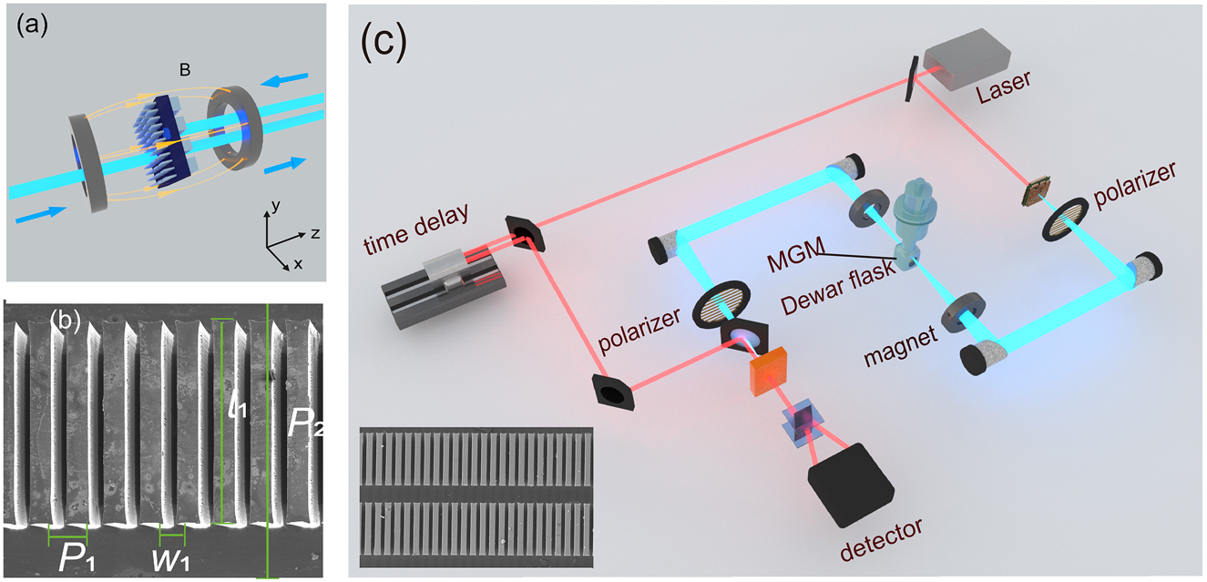
(a) The illustration of the transmission process for the designed GIG. (b) The SEM image of the Si meta-grating structure on the surface of the InSb substrate. The parameters of the structure are as follows: the transverse period P 1 = 77 μm, the width of the Si bar is W 1 = 54 μm, the length of the Si bar l 1 = 350 μm, the longitude period P 2 = 500 μm, and the etching depth of the grating is 170 μm. (c) The sketch map of the THz-TDMPS experiment setup. Inserted: the extended SEM image of the meta-grating with a larger field of view.
We use the terahertz time-domain magneto polarization spectroscopy (THz-TDMPS) system to experimentally demonstrated the property of the GIG as shown in Figure 2(c). Compared with the traditional THz-TDS system, the GIG sample is placed in a vacuum cryogenic Dewar bottle (T = 80 K in our work) with a pair of adjustable longitudinal magnets on both sides (B = 0–170 mT). There is one rotatable THz polarizer behind the THz source and the other one in front of the THz detector, which is used to generate and detect arbitrary THz polarization states, respectively. The details of the experimental system and the related data processing can be found in Part 2 of Supplementary Information.
At first, we investigated the transmission and polarization properties of the single meta-grating without InSb substrate. We measured the transmittance and phase difference along the major axis (along the y-axis) and minor axis (along the x-axis) of the grating. Meanwhile, we also obtained the numerical simulation results of the finite difference time domain (FDTD) method. The numerical modeling method can be found in Part 4 of Supplementary Information. As shown in Figure 3(a), the transmittance T x and T y for x-LP and y-LP are almost the same around 0.1–1 THz. And in Figure 3(b), the phase difference between x- LP and y-LP is decreasing with the frequency. In particular, the phase difference comes to 90° near 0.5 THz, so the grating is close to an ideal QWP. According to the above theoretical analysis, the GIG structure is expected to achieve efficient one-way transmission near this frequency point under the MF.
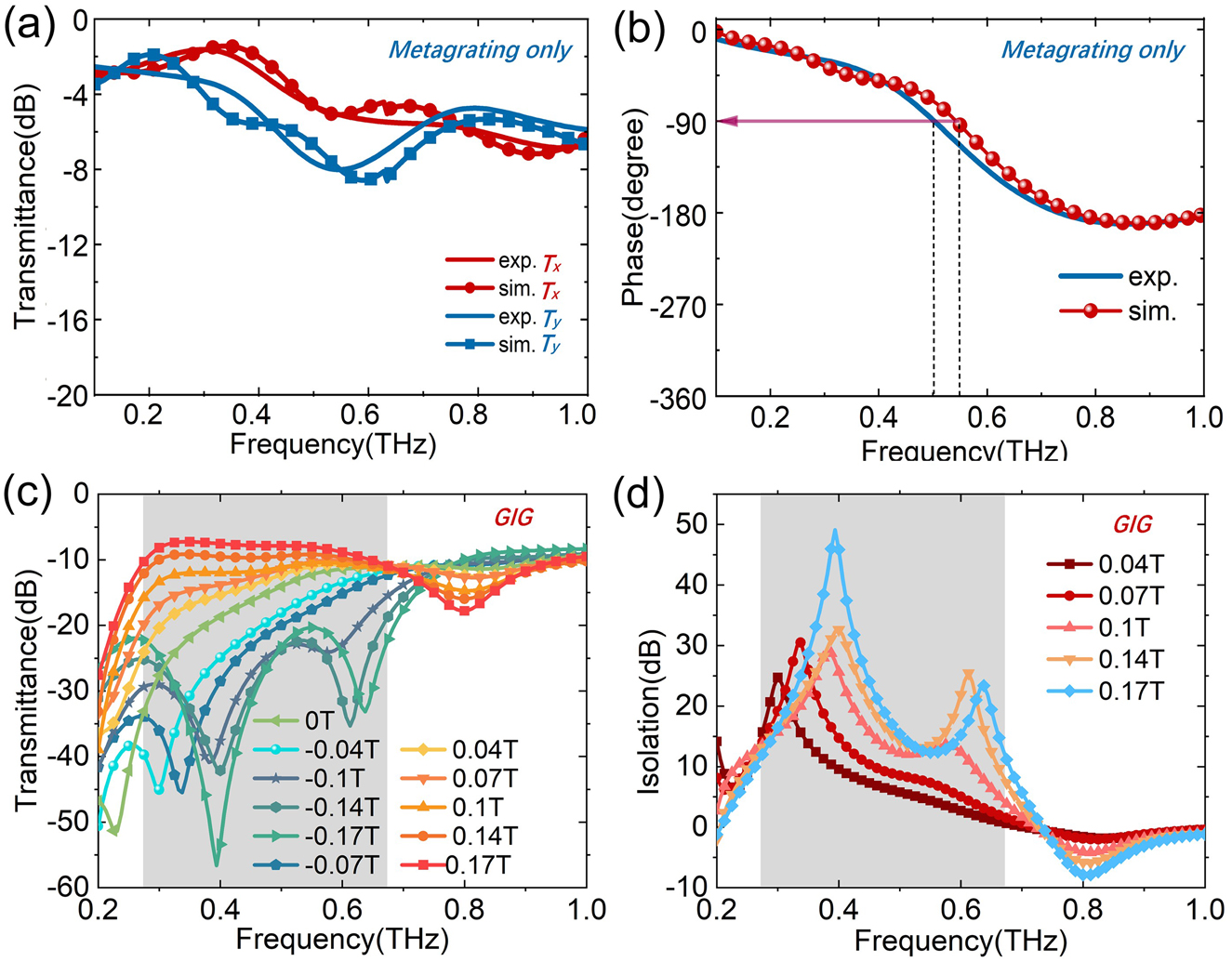
The simulative and experimental transmission spectra of the meta-grating on the Si substrate of x-LP (along with the minor axis) and y-LP (along with the long axis of grating); (b) the simulative and experimental phase difference of the grating between two orthogonal x-LP and y-LP. (c) The experimental transmission spectra from LP input to LP output of the GIG device under different MFs; (b) isolation of the GIG under different MFs.
Then, we focus on the nonreciprocal transmission property of the MO meta-grating with the GIG structure. We placed both THz polarizers to 0°, that is y-LP wave is incident into the GIG device, and the experimental system detects the y-LP component of the output wave. The transmission spectra of the LP wave passing through the GIG are shown in Figure 3(c). When B = 0 T, the transmittance is less than −10 dB in the frequency range of f < 0.7 THz. With the increase of the positive MFs, the cutting-off frequency gradually moves to the lower frequency as the transmittance increasing. On the contrary, when the negative MFs are applied, the cutting-off frequency gradually moves to a higher frequency with the decrease of transmittance. The experimental results are in good agreement with the theoretical calculation in Figure 1(d), and they are also verified by numerical simulations (see Part 4 of Supplementary information). Therefore, there is a nonreciprocal transmission band for the LP waves in the frequency range of 0.38–0.68 THz. Figure 3(d) shows the isolation between forward and backward transmission defined as Iso = T(+B) − T(−B) in dB. The isolation peak moves to high frequency and the isolation band (>10 dB) expands with the increase of MFs. Although the QWP point for the Si grating is 0.5 THz, when we combined the grating with the InSb, the impedance match condition of the grating is changed, thus making the QWP point of the GIG structure moves to the lower frequency. Therefore, when B = 0.17 T, the best isolation point can reach 50 dB at 0.42 THz with the 10 dB isolation bandwidth of 400 GHz.
Moreover, we analyzed the complete polarization state output through the GIG. When the frequency band deviates from the ideal QWP, the actual output wave will be an elliptical polarization state. We calculate the polarization ellipse as shown in Figure 4, we select two frequency points: f = 0.42 and 0.8 THz. When f = 0.42 THz, for the forward MFs, the amplitude growing with the MFs, and when B = 0.17 T, the output wave is almost the perfect LP state. However, for the backward MFs, the amplitude decreasing with the MFs, showing the isolation effect. For f = 0.8 THz, for the forward MFs, the polarization state turns counter clock-wise, but for the backward MFs, the polarization state rotates clockwise. Thus, in the higher frequency range of f > 0.8 THz, this structure shows the Faraday rotation effect which means the rotation angle can be turned by the MFs. For the details of related experimental measurement and data processing, please refer to Part 3 of Supplementary Information.
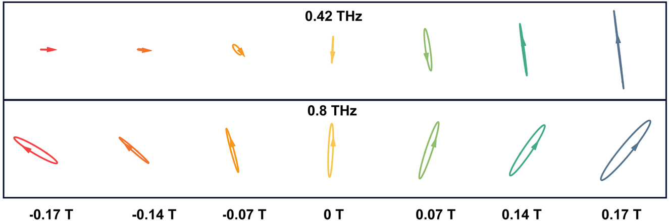
The polarization ellipse for the output wave for different MFs and frequencies.
2.3 Discussion for loss and bandwidth
Finally, as shown in Figures 3(c) and 5(c), the transmittance also reflects the total insertion loss of the device, and the lowest insertion loss is 6.7 dB for the first GIG structure and 6.9 dB for the second GIG structure, respectively. Two main factors contribute to the total loss of the device: the intrinsic absorption loss of the InSb and the surface reflection loss from the grating structure and interfaces. We think there are two ways to reduce the insertion loss in the future: one is to fabricate the InSb wafer with a lower intrinsic carrier concentration, and the second is to design a more optimized microstructure to achieve better impedance matching on the interfaces of the air/grating and grating/InSb.
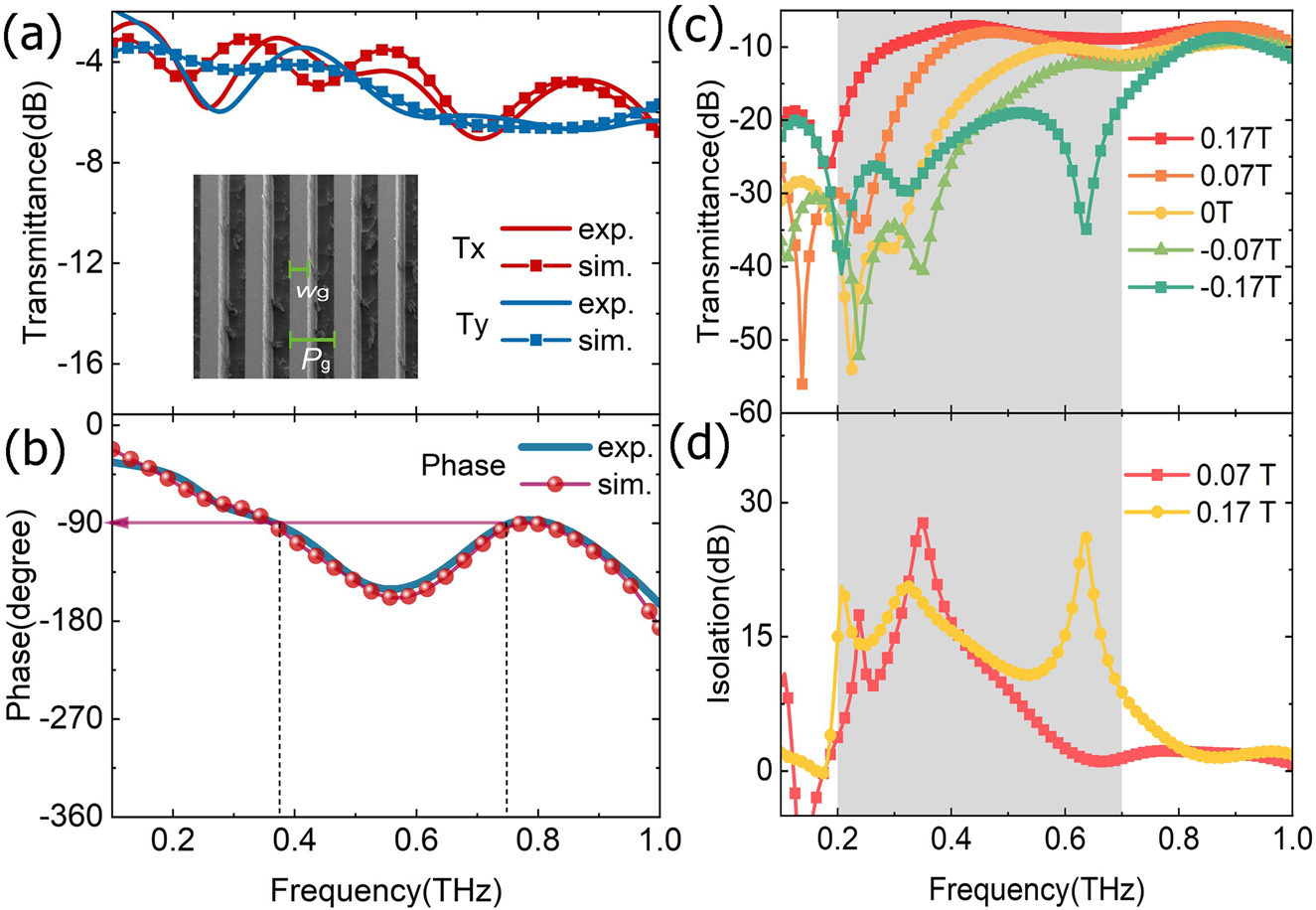
The simulative and experimental transmission spectra of the meta-grating without the InSb for x-LP (along with the minor axis) and y-LP (along with the long axis of grating); the parameters of the structure are as follows: the grating period P g = 200 μm, the width of the Si bar is W g = 75 μm and the etching depth of the grating is 200 μm. (b) The simulative and experimental phase difference of the grating between two orthogonal x-LP and y-LP. (c) The experimental transmission spectra from LP input to LP output of the GIG under different MFs; (d) isolation of the GIG under different MFs.
According to the nonreciprocity mechanism discussed in Section 2.1, the bandwidth of the device is determined by two factors: (1) the frequency band of InSb cyclotron resonance (including the position of resonance frequency determined by the MF and the resonance bandwidth determined by carrier collision frequency); (2) the frequency band of π/2 phase shift is realized by meta-grating as a THz QWP. When these two frequency bands are overlapped in the same frequency range, the perfect isolation case described in Eq. (7) can be achieved. The larger the overlap range is, the larger the 10 dB isolation bandwidth is. For a specific MO material, the cyclotron resonance bandwidth is constant, and the resonance center frequency can be tuned by the external magnetic field. Under these conditions, if a meta-grating can be designed as the THz QWP with enough broad bandwidth, a broadband LP isolator can be realized.
Therefore, we also designed and fabricated a subwavelength grating as a broadband QWP to obtain a broadband GIG. As shown in Figure 5(a), the transmittances of x- and y-LP components are almost the same. However, the phase difference between them has two 90° points at 0.38 and 0.75 THz as shown in Figure 5(b). By combining these grating with InSb, the transmittance and the isolation spectra under the different MFs can be seen in Figure 5(c) and (d). With the growth of the MFs, the transmittance increases under the positive MFs, while the transmittance decreases under the negative MFs. Different from the above results in Section 2.2, for the large MF (B = 0.17 T), the 10 dB isolation bandwidth is broader because these meta-gratings have two perfect QWP points which satisfy Eq. (7), its isolation band is located from 0.2 to 0.7 THz with the relative bandwidth of Δf/f cen > 110%, where f cen is the center frequency of this device.
3 Conclusions
In summary, by combining the meta-gratings with the gyroelectric semiconductor InSb, we proposed a THz isolator for the LP input to LP output. Through theoretical modeling and analysis, we demonstrate that the gyro-mirror symmetry of the InSb for the LP state can be broken by introducing a pair of orthogonal uniaxial anisotropies from the meta-gratings on the two sides of InSb. The experiment results indicate this THz MO device with the cascaded GIG structure isolation of 50 dB at 0.4 THz for the same LP input and output under the weak biased MF of 0.17 T, which are well consistent with the theoretical calculation and numerical simulation. Moreover, we further concluded the factors affecting the 10 dB isolation bandwidth of the device, and also demonstrated a broadband GIG structure with the 10 dB isolation bandwidth from 0.2–0.7 THz, and the relative bandwidth achieves 110%. This THz nonreciprocal transmission mechanism and device structures proposed in this work will contribute to the development of efficient THz magneto-optical isolators and polarization convertors, and promote the further development of THz high power sources and highly sensitive detection systems.
Funding source: National Natural Science Foundation of China
Award Identifier / Grant number: 61831012
Award Identifier / Grant number: 61971242
Funding source: National Key Research and Development Program of China
Award Identifier / Grant number: 2017YFA0701000
Funding source: Natural Science Foundation of Tianjin City
Award Identifier / Grant number: 19JCYBJC16600
-
Author contribution: Z-Y Tan: Investigation, Methodology, Resource, Writing-the original draft; F Fan: Conceptualization, Invistigation, Writing - review & editing, Supervision. D Zhao: Experiment. S-S Li: Scanning electron microscope operation. X-H Wang: Experiment administration. S-J Chang: Project administration. All the authors have accepted responsibility for the entire content of this submitted manuscript and approved submission.
-
Research funding: This work was supported by the National Natural Science Foundation of China (61831012, 61971242); National Key Research and Development Program of China (2017YFA0701000); Natural Science Foundation of Tianjin City (19JCYBJC16600).
-
Conflict of interest statement: The authors declare no conflicts of interest regarding this article.
References
[1] Y. Shoji, T. Mizumoto, H. Yokoi, et al.., “Magneto-optical isolator with silicon waveguides fabricated by direct bonding,” Appl. Phys. Lett., vol. 92, 2008, Art no. 071117. https://doi.org/10.1063/1.2884855.Search in Google Scholar
[2] W. Śmigaj, J. Romero-Vivas, B. Gralak, et al.., “Magneto-optical circulator designed for operation in a uniform external magnetic field,” Opt. Lett., vol. 35, p. 568, 2010.10.1364/OL.35.000568Search in Google Scholar PubMed
[3] Z. Wang and S. Fan, “Optical circulators in two-dimensional magneto-optical photonic crystals,” Opt. Lett., vol. 30, p. 1989, 2005. https://doi.org/10.1364/ol.30.001989.Search in Google Scholar PubMed
[4] H. S. Skulason, D. L. Sounas, F. Mahvash, et al.., “Field effect tuning of microwave Faraday rotation and isolation with large-area graphene,” Appl. Phys. Lett., vol. 107, 2015, Art no. 093106. https://doi.org/10.1063/1.4930065.Search in Google Scholar
[5] Y. Zhang, Q. Du, C. Wang, et al.., “Monolithic integration of broadband optical isolators for polarization-diverse silicon photonics,” Optica, vol. 6, p. 473, 2019. https://doi.org/10.1364/optica.6.000473.Search in Google Scholar
[6] S. Koenig, D. Lopez-Diaz, J. Antes, et al.., “Wireless sub-THz communication system with high data rate,” Nat. Photonics, vol. 7, p. 977, 2013. https://doi.org/10.1038/nphoton.2013.275.Search in Google Scholar
[7] K. B. Cooper, R. J. Dengler, N. Llombart, et al.., “THz imaging radar for standoff personnel screening,” IEEE Trans. Terahertz Sci. Technol., vol. 1, p. 169, 2011. https://doi.org/10.1109/tthz.2011.2159556.Search in Google Scholar
[8] D. Suzuki, S. Oda, and Y. Kawano, “A flexible and wearable terahertz scanner,” Nat. Photonics, vol. 10, p. 809, 2016. https://doi.org/10.1038/nphoton.2016.209.Search in Google Scholar
[9] B. Ng, S. M. Hanham, J. Wu, et al.., “Broadband terahertz sensing on spoof plasmon surfaces,” ACS Photonics, vol. 1, p. 1059, 2014. https://doi.org/10.1021/ph500272n.Search in Google Scholar
[10] Y. Jin, J. L. Reno, and S. Kumar, “Phase-locked terahertz plasmonic laser array with 2 W output power in a single spectral mode,” Optica, vol. 7, p. 708, 2020. https://doi.org/10.1364/optica.390852.Search in Google Scholar
[11] M. Tong, Y. Hu, Z. X. Xie, et al.., “Helicity-dependent THz emission induced by ultrafast spin photocurrent in nod-al-line semimetal candidate Mg3Bi2,” Opto-Electron. Adv., vol. 3, p. 200023, 2020. https://doi.org/10.29026/oea.2020.200023.Search in Google Scholar
[12] M. Tong, Y. Hu, Z. Wang, et al.., “Enhanced terahertz radiation by efficient spin-to-charge conversion in rashba-mediated Dirac surface states,” Nano Lett., vol. 21, p. 60, 2021. https://doi.org/10.1021/acs.nanolett.0c03079.Search in Google Scholar PubMed
[13] H. Zhao, X. Chen, C. Ouyang, et al.., “Generation and manipulation of chiral terahertz waves in the three-dimensional topological insulator Bi2Te3,” Adv. Photonics, vol. 2, 2020, Art no. 066003. https://doi.org/10.1117/1.ap.2.6.066003.Search in Google Scholar
[14] O. Mitrofanov, I. Brener, T. S. Luk, et al.., “Photoconductive terahertz near-field detector with a hybrid nanoantenna array cavity,” ACS Photonics, vol. 2, p. 1763, 2015. https://doi.org/10.1021/acsphotonics.5b00475.Search in Google Scholar
[15] V. V. Temnov, G. Armelles, U. Woggon, et al.., “Active magneto-plasmonics in hybrid metal–ferromagnet structures,” Nat. Photonics, vol. 4, p. 107, 2010. https://doi.org/10.1038/nphoton.2009.265.Search in Google Scholar
[16] D. Floess, J. Y. Chin, A. Kawatani, et al.., “Tunable and switchable polarization rotation with non-reciprocal plasmonic thin films at designated wavelengths,” Light Sci. Appl., vol. 4, p. e284, 2015. https://doi.org/10.1038/lsa.2015.57.Search in Google Scholar
[17] A. M. Shuvaev, G. V. Astakhov, A. Pimenov, et al.., “Giant magneto-optical Faraday effect in HgTe thin films in the terahertz spectral range,” Phys. Rev. Lett., vol. 106, p. 107404, 2011. https://doi.org/10.1103/physrevlett.106.107404.Search in Google Scholar
[18] F. Fan, S. Chen, and S. Chang, “A review of magneto-optical microstructure devices at terahertz frequencies,” IEEE J. Sel. Top. Quant. Electron., vol. 23, p. 8500111, 2017. https://doi.org/10.1109/jstqe.2016.2537259.Search in Google Scholar
[19] Y. Kinoshita, N. Kida, M. Sotome, et al.., “Terahertz radiation by subpicosecond magnetization modulation in the ferrimagnet LiFe5O8,” ACS Photonics, vol. 3, p. 1170, 2016. https://doi.org/10.1021/acsphotonics.6b00272.Search in Google Scholar
[20] M. Shalaby, M. Peccianti, Y. Ozturk, and R. Morandotti, “A magnetic non-reciprocal isolator for broadband terahertz operation,” Nat. Commun., vol. 4, p. 1558, 2013. https://doi.org/10.1038/ncomms2572.Search in Google Scholar PubMed PubMed Central
[21] D. Wang, B. Yang, W. Gao, et al.., “Photonic Weyl points due to broken time-reversal symmetry in magnetized semiconductor,” Nat. Phys., vol. 15, p. 1150, 2019. https://doi.org/10.1038/s41567-019-0612-7.Search in Google Scholar
[22] S. M. Hanham, A. I. Fernández-Domínguez, J. H. Teng, et al.., “Broadband terahertz plasmonic response of touching InSb disks,” Adv. Mater., vol. 24, p. OP226, 2012. https://doi.org/10.1002/adma.201202003.Search in Google Scholar PubMed
[23] T. Li, F. Fan, Y. Ji, et al.., “Terahertz tunable filter and modulator based on magneto plasmon in transverse magnetized InSb,” Opt. Lett., vol. 45, no. 1, p. 1, 2020. https://doi.org/10.1364/ol.45.000001.Search in Google Scholar
[24] Q. Mu, F. Fan, S. Chen, et al.., “Tunable magneto-optical polarization device for terahertz waves based on InSb and its plasmonic structure,” Photon. Res., vol. 7, p. 325, 2019. https://doi.org/10.1364/prj.7.000325.Search in Google Scholar
[25] S. Lin, S. Silva, J. Zhou, et al.., “A one-way mirror: high-performance terahertz optical isolator based on magnetoplasmonics,” Adv. Opt. Mater., vol. 6, p. 1800572, 2018. https://doi.org/10.1002/adom.201800572.Search in Google Scholar
[26] Z. Wang, Y. Chong, J. D. Joannopoulos, et al.., “Observation of unidirectional backscattering-immune topological electromagnetic states,” Nature, vol. 461, p. 772, 2009. https://doi.org/10.1038/nature08293.Search in Google Scholar PubMed
[27] X. Xu, S. A. Majetich, and S. A. Asher, “Mesoscopic monodisperse ferromagnetic colloids enable magnetically controlled photonic crystals,” J. Am. Chem. Soc., vol. 124, p. 13864, 2002. https://doi.org/10.1021/ja026901k.Search in Google Scholar PubMed
[28] K. Lodewijks, N. Maccaferri, T. Pakizeh, et al.., “Magnetoplasmonic design rules for active magneto-optics,” Nano Lett., vol. 14, p. 7207, 2014. https://doi.org/10.1021/nl504166n.Search in Google Scholar PubMed
[29] V. I. Belotelov, I. A. Akimov, M. Pohl, et al.., “Enhanced magneto-optical effects in magnetoplasmonic crystals,” Nat. Nanotechnol., vol. 6, p. 370, 2011. https://doi.org/10.1038/nnano.2011.54.Search in Google Scholar PubMed
[30] J. Qin, L. Deng, T. Kang, et al.., “Switching the optical chirality in magnetoplasmonic metasurfaces using applied magnetic fields,” ACS Nano, vol. 14, p. 2808, 2020. https://doi.org/10.1021/acsnano.9b05062.Search in Google Scholar PubMed
[31] L. E. Kreilkamp, V. I. Belotelov, J. Y. Chin, et al.., “Waveguide-plasmon polaritons enhance transverse magneto-optical Kerr effect,” Phys. Rev. X, vol. 3, 2013, Art no. 041019. https://doi.org/10.1103/physrevx.3.041019.Search in Google Scholar
[32] S. Chen, F. Fan, X. Wang, et al.., “Terahertz isolator based on nonreciprocal magneto-metasurface,” Opt Express, vol. 23, p. 1015, 2015. https://doi.org/10.1364/oe.23.001015.Search in Google Scholar
[33] J.-M. Poumirol, P. Q. Liu, T. M. Slipchenko, et al.., “Electrically controlled terahertz magneto-optical phenomena in continuous and patterned graphene,” Nat. Commun., vol. 8, p. 14626, 2017. https://doi.org/10.1038/ncomms14626.Search in Google Scholar PubMed PubMed Central
[34] S. H. Mousavi, A. B. Khanikaev, J. Allen, et al.., “Gyromagnetically induced transparency of metasurfaces,” Phys. Rev. Lett., vol. 112, p. 117402, 2014. https://doi.org/10.1103/physrevlett.112.117402.Search in Google Scholar
[35] M. Tamagnone, C. Moldovan, J.-M. Poumirol, et al.., “Near optimal graphene terahertz non-reciprocal isolator,” Nat. Commun., vol. 7, p. 11216, 2016. https://doi.org/10.1038/ncomms11216.Search in Google Scholar PubMed PubMed Central
Supplementary Material
The online version of this article offers supplementary material (https://doi.org/10.1515/nanoph-2021-0416).
© 2021 Zhiyu Tan et al., published by De Gruyter, Berlin/Boston
This work is licensed under the Creative Commons Attribution 4.0 International License.
Articles in the same Issue
- Frontmatter
- Reviews
- Spin photonics: from transverse spin to photonic skyrmions
- Multiple excitons dynamics of lead halide perovskite
- Recent advances in bianisotropic boundary conditions: theory, capabilities, realizations, and applications
- Research Articles
- All-optical modulation based on MoS2-Plasmonic nanoslit hybrid structures
- Graphdiyne-decorated microfiber based soliton and noise-like pulse generation
- True- and quasi-bound states in the continuum in one-dimensional gratings with broken up-down mirror symmetry
- Toward white light emission from plasmonic-luminescent hybrid nanostructures
- Observation of elastic heterogeneity and phase evolution in 2D layered perovskites using coherent acoustic phonons
- Topological protection of continuous frequency entangled biphoton states
- Emission kinetics of HITC laser dye on top of arrays of Ag nanowires
- Ultra-narrowband and highly-directional THz thermal emitters based on the bound state in the continuum
- High-performance flexible surface-enhanced Raman scattering substrate based on the particle-in-multiscale 3D structure
- A mixture-density-based tandem optimization network for on-demand inverse design of thin-film high reflectors
- Azimuthally and radially polarized orbital angular momentum modes in valley topological photonic crystal fiber
- Plasmonic interference modulation for broadband nanofocusing
- Grayscale-patterned metal-hydrogel-metal microscavity for dynamic multi-color display
- Waveguide Schottky photodetector with tunable barrier based on Ti3C2T x /p-Si van der Waals heterojunction
- Linear-polarized terahertz isolator by breaking the gyro-mirror symmetry in cascaded magneto-optical metagrating
- Nonlinear plasmonic response in atomically thin metal films
- Thermal near-field tuning of silicon Mie nanoparticles