Effect of Cu addition on microstructure and corrosion behavior of Al–15Mg2Si composite
-
Leila Hesami, born in 1998, studied Materials Science at Imam Khomeini International University. She received her M.Sc. in Materials Engineering in 2019.
Reza Taghiabadi, Associate Prof., born in 1975, studied Materials Science at the University of Tehran. He received his PhD in Materials Engineering in 2007. Since then, he has been working as a faculty member at the Department of Metallurgy and Materials Science, Imam Khomeini International University, Qazvin, Iran.
Mohammad Hossein Ghoncheh, born in 1988, holds his MSc degree in Materials Science and Engineering from the McMaster University, 2019. Since 2019, he has worked as a research assistant in Marine Additive Manufacturing Centre of Excellence (MAMCE) at the University of New Brunswick, as well as Quality Management Associate in Steel Processing – Gerdau North America.
Mohammad Emami, Assistant Prof., born in 1979, studied Materials Science and Engineering at Tarbiat Modares University. He received his PhD in Materials Engineering in 2013. From 2015 to 2017 he worked as a research staff at Tokyo Institute of Technology and from 2017 to 2018 he got a postdoc position at Tarbiat Modares University. Since then, he has been a faculty member at the Department of Materials Science and Engineering, University of Boanb, Bonab, Iran.

 and
and
Morteza Saghafi Yazdi, Associate Prof., born in 1985, studied Materials Science at Amir Kabir University. He received his PhD in Materials Engineering in 2014. Since then, he has been working as a faculty member at Imam Khomeini International University.

Abstract
The Cu effect on the microstructure and corrosion resistance of Al–15Mg2Si composites was studied. The results showed that Cu addition decreased the average size of primary Mg2Si (Mg2SiP) particles, changed the hopper-like Mg2SiP particles to polyhedrals, and caused the formation of θ-Al2Cu and Q-Al5Mg8Si6Cu2 compounds in the composite matrix. According to the image analysis results, increasing the Cu content from 0.01 to 5 wt% halved the average size of Mg2SiP particles, increased their fraction by about 40 %, and increased the composite porosity content. The electrochemical impedance spectroscopy showed that adding 5 wt% of Cu resulted in an increase of about 3.7 times in the corrosion resistance as compared to Al–15Mg2Si composite. The beneficial effects of Cu were also confirmed by the potentiodynamic polarization experiments. Cu addition seems to promote less intense general corrosion than the base alloy’s localized attack.
1 Introduction
Owing to the in-situ formation of Mg2SiP particles in the matrix of hypereutectic Al–Mg2Si alloys, they are generally considered as composite [1]. The FCC-structured Mg2Si particles are quite hard (4500 MN m−2), and due to a high melting point (1085 °C), low density (1.99 g cm−3), low thermal expansion coefficient (7.5 × 10⁻⁶ K−1), and reasonably high Young’s modulus (120 GPa) [2, 3], their formation leads to a substantial increase in the hardness, specific strength, and tribological properties of Al–15Mg2Si composites at both room and high temperatures. However, achieving appropriate properties requires optimizing the geometrical parameters and distribution of Mg2Si reinforcements within the composite microstructure. Otherwise, the in-situ crystallization of Mg2SiP compounds as irregular-shaped coarse particles/dendrites and Mg2SiE compounds as coarse plate-like crystals within the matrix impairs the composite properties.
Efforts have been made to modify or refine the in-situ formed Mg2Si particles and improve their distribution within the composite matrix [4]. However, most previous studies concentrated on improving mechanical and/or tribological properties rather than the corrosion behavior of Al–Mg2Si composites. Nonetheless, because the corrosion potential of Mg2Si differs greatly from that of the α-Al matrix, the geometry, and distribution of Mg2Si in the matrix could greatly affect the corrosion behavior of the composite material [5].
Chemical modification, a technique capable of changing the size and morphology of Mg2Si particles, has been widely used to refine the microstructure and enhance the mechanical properties, tribological performance, and corrosion resistance of Al–Mg2Si composites. Many elements such as Sr, Ca, Y, and so on have been proposed to modify Mg2Si particles. Adding these elements within their optimum concentration range refines and/or alters the morphology of Mg2Si particles, effectively whilst their excess addition which is called over-modification may impair composite properties [4, 6, 7].
Copper is an element whose modification effect on Mg2Si particles has been demonstrated. Palta et al. [8] suggested that the Cu addition decreased both the average size and volume fraction of Mg2SiP in an Al–12Si–20Mg composite. In the study of Hesami et al. [9], Cu alloying led to the refinement and morphology modification of Mg2Si particles. Also, the formation of Cu-rich phases such as θ-Al2Cu and Q-Al5Mg8Si6Cu2 in the Al–15Mg2Si composite was promoted.
Changing the size, morphology, and fraction of Mg2Si particles/Cu-rich compounds most likely causes significant changes in the composite corrosion behavior. However, a review of the literature indicates that the role of Cu alloying in the corrosion resistance of Al–Mg2Si alloys has not been well investigated. In one of the few studies, the effect of Cu (up to 4.0 wt%) on the corrosion behavior of an Al–12Si–20Mg alloy in a NaCl + HCl solution was studied [8]. It was shown that Cu slightly reduced the corrosion loss. This effect was attributed to converting the script-shaped eutectic Mg2SiE particles to a combination of Cu- and Si-rich intermetallics. Therefore, considering the industrial importance of hypereutectic Al–15Mg2Si composite, the present study explores the corrosion behavior of Al–15Mg2Si composites in a 3.5 wt% NaCl solution in relation to microstructural changes caused by adding 1.0, 3.0, and 5.0 wt% Cu.
2 Materials and methods
The primary Al–15Mg2Si ingots were made by melting commercially pure aluminum, silicon, and magnesium in a SiC crucible using a resistance furnace. Having held at 750 °C for ∼15 min and slightly stirred for ∼20 s, the melt was poured into a steel mold. For Cu addition, appropriate amounts of pure Cu in the form of short thin rods were added to the re-melted base alloy to make Al–15Mg2Si-xCu (x = 1, 3, and 5 wt%) composites with the geometry/dimensions shown schematically in Figure 1. More details on the casting procedure and alloy preparation could be found in [9].

Schematic representation of the geometry/dimensions of the Al–Mg2Si composites together with the mold design.
Surface preparation of the samples was performed by standard metallography procedures followed by chemical etching using 2 mL HF and 98 mL distilled water etchant for 10 s. The SEM observations were performed using a Tescan-Vega scanning electron microscope (SEM) equipped with an energy dispersive spectroscopy (EDS) device for elemental analysis. The image analysis was conducted by a portrait image analysis system (Clemex Vision Pro. 3.5.025). The porosity content of the samples was measured by Archimedes’ immersion method [10].
Electrochemical experiments were performed in 3.5 wt% NaCl solution utilizing an IviumStat model potentiostat/galvanostat. A classical three-electrode cell comprising the composite sample as the working electrode, silver/silver chloride as the reference electrode, and platinum as the reference electrode was used. The exposed surface of the alloy (a 10 × 10 mm square) was polished up to 2000 grit and ultrasonically cleaned in ethanol just before corrosion tests. Electrochemical impedance spectroscopy (EIS) was performed in a potential amplitude of 10 mV (vs. OCP) and frequency range of 10 kHz–100 mHz after 3600 s of immersion to reach steady-state conditions. The potentiodynamic polarization curves were recorded from −1.5 V to +1 V (vs. Ag/AgCl) with a scanning rate of 1 mV s−1. The corrosion current density (icorr) and corrosion potential (Ecorr) were measured using the Tafel method.
3 Results and discussion
3.1 Microstructural characterization
Figure 2 shows the deep-etched microstructure of the Al–15Mg2Si composite. Based on the liquidus projection of the Al–Mg–Si equilibrium phase diagram (Figure 3a) [11], the solidification of the base hypereutectic alloy begins with the formation of Mg2SiP phase. Following this transformation, due to the consumption of Si and Mg atoms, the liquid composition moves along lines SA and then AB in which the binary eutectic reaction occurs, i.e. L → L1 + Mg2SiP → L2 + (α-Al + Mg2Si)E + Mg2SiP → (α-Al + Mg2Si)E + Mg2SiP [11]. Therefore, the microstructure of the base composite (0.01 wt% Cu) consists of coarse Mg2SiP polyhedrals and eutectic cells comprising α-Al and Mg2SiE particles (Figure 2). The EDS analysis of Mg2Sip and Mg2SiE particles in Figure 2 showed a respective Mg to Si content of 68 to 32 and 66.3 to 33.7 (compositions in wt%).

Deep-etched SEM microstructure of the base composite.
![Figure 3:
a) Al–Mg–Si liquidus projection [11], b) Al–Mg–Si–Cu partial liquidus projection depicting quaternary liquidus lines [12].](/document/doi/10.1515/mt-2023-0217/asset/graphic/j_mt-2023-0217_fig_003.jpg)
The microstructure of Cu-added composites is shown in Figure 4. It is obvious that the size and area fraction of bright Cu-rich phases increased as the Cu content increased. According to the partial liquidus projection of the Al–Mg–Si–Cu phase diagram (Figure 3b), after Mg2SiP particles form, the liquid composition in the Cu-added composites moves towards the ternary eutectic point E1 in which the liquid transforms into blocky-shape θ-Al2Cu and honeycomb Q-Al5Mg8Si6Cu2 phases [12]. The detailed morphology of these intermetallics is shown in Figure 5 and the corresponding EDS point analysis could be seen in Table 1.

Microstructure of Cu-added Al–15Mg2Si composites, a) Al–15Mg2Si–1Cu, b) Al–15Mg2Si–3Cu, c) Al–15Mg2Si–5Cu.
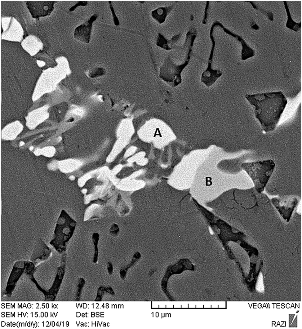
SEM micrograph showing Q-phase (Area A) and θ-phase (Area B) in the microstructure of Al–15Mg2Si composite.
EDS analysis of areas A and B shown in Figure 5 (wt%).
| Mg | Al | Si | Fe | Cu | |
|---|---|---|---|---|---|
| Area A, Q-phase | 36.3 | 24.1 | 28.5 | 1 | 10.1 |
| Area B, θ-phase | – | 40.9 | – | – | 59.1 |
Cu affected the composite’s microstructure by (i) increasing the content of Cu-rich particles (brighter contrast phases in Figure 3), (ii) refining, and (iii) changing the morphology of Mg2Si particles. The graphical representation of the effects of Cu on the average size, area, and perimeter of the Mg2Si particles based on the image analysis results of Figure 4 denotes that finer Mg2Si were obtained by increasing the Cu content (Figure 6a). The fraction of Mg2SiP particles also experienced significant growth of about 40 % (Figure 6b).

Effect of Cu on a) average size and area, and perimeter of Mg2SiP particles, b) fraction of Mg2SiP and Cu-rich phases and porosity percentage in Al–15Mg2Si composite.
According to the proposed mechanisms [9], the modification/refinement of Mg2Si particles in Cu-added composites may be explained by the nucleation of Mg2Si on the Cu-rich compounds, poisoning the preferred growth planes of Mg2Si phase by absorption of Cu atoms, or promoting isotropic growth of Mg2Si particles by the copper-induced multiple twinning mechanism. However, the crystal structure and lattice parameters of Mg2Si (anti-fluorite face-centered cubic, a = 0.6338 nm) [13] are quite different from those of Cu-rich compounds (θ-phase: tetragonal, a = b = 0.428 nm and c = 0.24 nm) [14] and Q-phase (hexagonal: a = 1.04 nm and c = 0.405 nm) [15]. Moreover, the Cu-rich phases have a lower melting point than the Mg2Si phase. Therefore, these compounds are unlikely to serve as the heterogeneous nucleation sites for Mg2Si particles. On the other hand, the ratio of rCu/rSi is 1.23 which is lower than the value of 1.54–1.85 reportedly required for twinning [16]. Therefore, poisoning appears to be the predominant modification mechanism in which the absorption of Cu atoms at the growing interfaces of the Mg2Si particles changes the interfacial energy and suppresses the anisotropic growth [15, 16].
According to Figure 6b, higher Cu additions caused a higher volume percentage of microporosities to form. The porosity content, in this regard, increased from ∼0.6 vol% in the Cu-free structure to about 1.67, 3.95, and 5.9 vol% in 1, 3, and 5 wt% Cu-containing composites, respectively. Based on the cooling curve analysis of Cu-containing composites (Figure 7a) augmenting the porosity content by Cu addition is seemingly due to the increased freezing range of the composite where its solidus and nucleation points were progressively lowered and raised, respectively (Figure 7b). According to [9], in wide freezing range alloys, at the last stages of solidification, the pockets of molten metal are isolated in the mushy zone and therefore deprived of liquid metal that would compensate for the solidification shrinkage. Under this circumstance, shrinkage micropores are likely to be formed in the microstructure (Figure 4).

Thermal analysis data of the Al–15Mg2Si alloy, a) cooling curves, b) freezing range, nucleation, and solidus temperatures at various Cu contents.
In addition, the enrichment of Cu atoms in front of the solidification front enhances the activity coefficient of hydrogen, giving rise to a substantial reduction in its solubility in the molten portion of samples [17, 18] increasing its porosity content.
3.2 Corrosion behavior
The potentiodynamic polarization curves of the base, Al–15Mg2Si–3Cu, and Al–15Mg2Si–5Cu samples could be seen in Figure 8. As seen, these alloys showed almost similar behaviors with a small move toward more active potentials. This was ascribed to the more positive potential of Al2Cu than the surrounding matrix which increases the anodic reactivity [19]. Also, a reduction in the corrosion current density (icorr) by increasing the Cu content was observed. Both Cu-added alloys showed a very narrow region of almost constant icorr which may show an unstable passivity. The passive potential was about −0.75 V and −0.72 V and the breakdown potential was about −0.67 V and −0.62 V for Al–15Mg2Si–3Cu and Al–15Mg2Si–5Cu composites, respectively. A summary of the corrosion data including Ecorr, icorr, corrosion rate, βa, and βc is shown in Table 2. Al–15Mg2Si–5Cu with an icorr of 0.164 mA cm−2 showed the lowest corrosion rate, while the base alloy was the lowest corrosion-resistant alloy with an icorr of about 0.3 mA cm−2. These results suggest that adding Cu to the composition of the Al–Mg2Si alloy improved its corrosion behavior.

Potentiodynamic polarization curves for the base, Al–15Mg2Si–3Cu, and Al–15Mg2Si–5Cu samples in 3.5 wt% NaCl solution.
Polarization parameters for different specimens in 3.5 % NaCl solution.
| Ecorr (V) | icorr (mA cm−2) | βa (V decade−1) | βc (V decade−1) | Corrosion rate (mm y−1) | |
|---|---|---|---|---|---|
| Base | −0.7391 | 0.3 | 0.041 | 2.361 | 0.9828 |
| Al–15Mg2Si–3Cu | −0.8645 | 0.246 | 0.076 | 0.892 | 0.8056 |
| Al–15Mg2Si–5Cu | −0.9507 | 0.164 | 0.072 | 0.605 | 0.5369 |
The Bode and Nyquist diagrams obtained from EIS of the base, Al–15Mg2Si–3Cu, and Al–15Mg2Si–5Cu samples after 1 h immersion in a 3.5 wt% NaCl solution and the corresponding equivalent circuit could be seen in Figure 9. The Bode diagram (Figure 9a) showing the modulus of impedance (|Z|) versus frequency could be divided into three regions showing alloys polarization resistance at low frequencies (0.01–1 Hz), double layer behavior at intermediate frequencies (1–100 Hz), and the ohmic resistance of 3.5 wt% NaCl solution at high frequencies (100–10,000 Hz). The higher |Z| value in low frequencies signifies a higher corrosion resistance [20]. Thus, agreeing with polarization results, it is observed that Cu addition considerably enhanced the corrosion resistance of the alloy.

EIS test results of the base, Al–15Mg2Si–3Cu, and Al–15Mg2Si-5Cu samples in 3.5 wt% NaCl solution, a) Bode diagram, b) Nyquist diagram, c) suggested equivalent circuit.
The Nyquist diagrams (Figure 9b) show two distinct arcs (time constants), a smaller one at higher frequencies representing the response of the corrosion products (oxide films) and an arc with a larger diameter at intermediate to low frequencies that shows the charge transfer behavior of the alloy. The larger diameter of the capacitive arcs of the Al–15Mg2Si–5Cu sample verifies its higher corrosion resistance in accordance with the polarization test results. The EIS data were fitted by the equivalent circuit shown in Figure 9c using the Iviumsoft software simulation. This circuit that fitted well with the impedance data of the present experiments has been widely accepted in the case of Al alloys with and without second-phase particles [20], [21], [22], [23]. Some researchers have proposed more complicated circuits to take into account the role of intermetallics, separately [24]. However, a good fit was not obtained by those circuits in the present study. The relevant EIS parameters are shown in Table 3. In this Table, R s shows the solution resistance, Qox, n1, and Rox mean the capacitance of the surface oxide, the dispersion coefficient, and the oxide film resistance, respectively. Qdl, n2, and Rct denote the capacitive response of the double layer of oxide film-electrolyte interface, the dispersion coefficient, and the charge transfer resistance at the oxide-metal interface. The charge transfer resistance (Rct) describes the electron transfer across the surface which is a measure of the integrity and protectiveness of the surface films and the subsequent corrosion resistance of the alloy [20]. The sum of Rct and Rox denotes the corrosion resistance of the alloy [21]. According to Table 3, the Rox and Rct for Al–15Mg2Si–5Cu were higher than those for Al–15Mg2Si–3Cu and base materials which verify the highest corrosion resistance of Al–15Mg2Si–5Cu. The base material, on the other hand, showed the lowest corrosion resistance.
Impedance parameters for the base, Al–15Mg2Si–3Cu, and Al–15Mg2Si–5Cu alloys based on the equivalent circuit in Figure 9c.
| R s (Ωcm2) | Qox (SnΩ−1cm−2) | n 1 | Qdl (SnΩ−1cm−2) | n 2 | Rox (Ωcm2) | Rct (kΩcm2) | Chi-square | |
|---|---|---|---|---|---|---|---|---|
| Base | 99.3 | 8.9E−5 | 0.81 | 6.3E−4 | 0.77 | 2940 | 14 | 0.0014 |
| Al–15Mg2Si–3Cu | 80.3 | 9.3E−5 | 0.83 | 4.5E−4 | 0.96 | 3740 | 55 | 0.001 |
| Al–15Mg2Si–5Cu | 69.5 | 8.2E−5 | 0.84 | 3.9E−4 | 0.88 | 4580 | 59 | 0.0011 |
Constant phase elements of Qox and Qdl denote a deviation from the ideal capacitor [20] which is generally caused by the presence of surface heterogeneities/discontinuities such as roughness and porosity [25]. Here, Qox might be attributed to the discontinuity of the oxide film caused by second phases and porosities which will be discussed later.
SEM micrographs of the corroded surfaces of the base, Al–15Mg2Si–3Cu, and Al–15Mg2Si–5Cu samples after 24 h immersion in the 3.5 wt% NaCl solution are shown in Figure 10. The comparison of the corroded surfaces shows that in the base Al–Mg2Si composite, the Mg2Si particles were severely attacked (Figure 10a–c) by the solution based on the mechanism describes above and pits were formed in the vicinity of the particles. However, in Cu-containing alloys, the pitting corrosion was seemingly concentrated at the periphery of the Al2Cu particles (Figure 10f) and no pronounced damage was observed in the matrix around the Mg2Si particles. This behavior could be explained as follows:

SEM micrographs of the corroded samples after 24 h immersion in 3.5 wt% NaCl solution, a) Base, b) Base, c) an enlarged view of the Base, d) Al–15Mg2Si–3Cu, e) Al–15Mg2Si–5Cu, f) an enlarged view of Al–15Mg2Si–5Cu.
The formation of various compounds with different electrochemical potentials in the as-cast microstructure of Al alloys makes them quite susceptible to localized corrosion, especially in chloride solutions. Because, in this condition, the surface oxide film cannot provide complete protection [26]. It is well accepted that due to the presence of considerable amounts of Mg in the composition, Mg2Si is attacked preferentially and acts as an anodic phase when coupled with Al in neutral saline solutions [5, 27, 28]. The dissolution starts with the preferential oxidation of Mg in the compound through the anodic reaction: Mg → Mg2+ + 2e− [29]. The loss of Mg leads to the enrichment of the more noble Si in the compound and the subsequent polarity transformation of the remaining Mg2Si to a cathodic one. Once this happens, the anodic oxidation of the Al matrix starts via the reaction Al → Al3+ + 3e− and the release of Al3+ to the electrolyte causes Al dissolution/corrosion [30]. A cathodic reaction corresponding to neutral pH values happens on more noble phases as follows: 2H2O + O2 + 4e− → 4OH− [29]. The dissolution of the Al surrounding the Si-enriched Mg2Si particles could form corrosion damages called peripheral pits owing to their morphology (Figure 10a). A bigger cathode size leads to a higher anodic current density and more intense corrosion of the surrounding Al matrix. Chloride ions are reported to disrupt the protective film and promote pit formation in Al alloys. Al3+ ions may react with Cl− ions in the solution through the reaction Al3+ + Cl− + H2O → Al(OH)3 + 3HCl and form aluminum hydroxide where the surface is not protected [26]. Intermetallic particles are sites for the initiation of localized corrosion because of the integrity loss of the oxide film at these sites [31].
The addition of Cu increased the size and fraction of Al2Cu particles in the alloys (Figure 4). This compound has a more positive potential than the matrix and provokes cathodic reactions and localized corrosion [32, 33]. Also, the microporosity percentage was increased by increasing Cu content (Figure 6). This in turn could have negative effects on the corrosion properties of the alloy probably because of increasing the contact area of the alloy and electrolyte [34, 35]. So, in an Al matrix, the Cu addition seems to be deleterious for the corrosion resistance of the alloy. Conversely, in this study, Cu played a remarkably beneficial role in the corrosion behavior of the alloy. The stability of passive oxide film in Al alloys depends on factors like grain size and distribution of particles [36]. Alloys Al–15Mg2Si–3Cu and Al–15Mg2Si–5Cu were characterized by much smaller Mg2Si particles than the base alloy (Figures 2 and 5). According to Hesami et al. [9], Cu addition also refined the morphology of eutectic Mg2Si. This is inferred that a finer matrix structure could also be obtained, accordingly. The high reactivity and diffusivity of the grain boundaries promote the diffusion of oxygen and therefore the formation of passive oxide films is expectedly accelerated. Rao et al. [37] suggested that in the case of an Al–30Si alloy, pitting potential decreased, and passivity improved by refining the microstructure and Si particles. The effect of finer second phases on the improvement of the corrosion behavior of Al alloys was also reported by Mitelea et al. [38]. Based on the preceding discussion, faster formation of an alumina film on the surface of the Cu-containing alloys is expected. This mechanism could contribute at least partly to the corrosion resistance of Al–15Mg2Si–3Cu and Al–15Mg2Si–5Cu alloys.
It was argued that intermetallic particles act against the formation of a perfect passive film. However, this effect is depressed when the particles are reduced in size and distributed more uniformly. Although a clear explanation was not presented in the literature, it was argued that the propagation of corrosion pits is hampered in such conditions [36, 37]. It seems that in the case of smaller particles, passive film is more integrated which manifested itself in the EIS results (Table 3). It could be stated that in Al–15Mg2Si–3Cu and Al–15Mg2Si–5Cu with finer Mg2Si particles (Figure 5), the specific surface area of the particles in the matrix increases. So, the ratio of the cathodic to anodic surface area is reduced compared to the base alloy. This may slow down the dealloying of Mg from the anodic Mg2Si. Thus, the later polarity change and pit formation in the Al matrix around Mg2Si particles are retarded. Therefore, the alloy was less damaged and peripheral pits more or less formed around the more cathodic Cu intermetallics (which are sparse compared with Mg2Si) as shown in Figure 10d–f. This supports the higher corrosion resistance of Al–15Mg2Si–3Cu and Al–15Mg2Si–5Cu observed in the polarization and EIS experiments.
Based on the above discussion, it could be said that the Cu addition on the one hand increases the chance of localized corrosion by the formation of less active Al2Cu particles and increasing micropores, and on the other hand its effect on the microstructure refinement aids in the rapid formation and healing the passive film. It is anticipated that the latter effect works much better to provide the alloys with higher corrosion resistance than the base alloy.
4 Conclusions
The addition of Cu substantially refined the Mg2SiP particles and modified their hopper-like morphology. According to the image analysis results, increasing the Cu content from 0.01 to 5 wt% reduced the average size of Mg2SiP particles from 12.1 to 6.1 μm and increased their fraction by about 40 %.
An increase in the Cu content from 1 to 5 wt% increased the volume fraction of θ-Al2Cu and Q-Al5Mg8Si6Cu2 compounds from 1.7 % to 8.1 %. At the same time, the composite porosity content increased by almost 10 times.
An increase in the Cu content from 1 to 5 wt% increased the corrosion resistance of the alloy. According to Tafel measurements, the corrosion current density decreased by almost 2 times in the alloy with 5 wt% Cu. The EIS experiments accordingly showed a more than 3.5 % increase in the polarization/corrosion resistance of the latter alloy compared to the base alloy. The higher corrosion resistance was attributed to a more compact and integrated oxide film and lower localized corrosion.
About the authors
Leila Hesami, born in 1998, studied Materials Science at Imam Khomeini International University. She received her M.Sc. in Materials Engineering in 2019.
Reza Taghiabadi, Associate Prof., born in 1975, studied Materials Science at the University of Tehran. He received his PhD in Materials Engineering in 2007. Since then, he has been working as a faculty member at the Department of Metallurgy and Materials Science, Imam Khomeini International University, Qazvin, Iran.
Mohammad Hossein Ghoncheh, born in 1988, holds his MSc degree in Materials Science and Engineering from the McMaster University, 2019. Since 2019, he has worked as a research assistant in Marine Additive Manufacturing Centre of Excellence (MAMCE) at the University of New Brunswick, as well as Quality Management Associate in Steel Processing – Gerdau North America.
Mohammad Emami, Assistant Prof., born in 1979, studied Materials Science and Engineering at Tarbiat Modares University. He received his PhD in Materials Engineering in 2013. From 2015 to 2017 he worked as a research staff at Tokyo Institute of Technology and from 2017 to 2018 he got a postdoc position at Tarbiat Modares University. Since then, he has been a faculty member at the Department of Materials Science and Engineering, University of Boanb, Bonab, Iran.
Morteza Saghafi Yazdi, Associate Prof., born in 1985, studied Materials Science at Amir Kabir University. He received his PhD in Materials Engineering in 2014. Since then, he has been working as a faculty member at Imam Khomeini International University.
-
Author contributions: All the authors have accepted responsibility for the entire content of this submitted manuscript and approved submission.
-
Research funding: No funding was received for conducting this study.
-
Conflict of interest statement: The authors have no competing interests to declare that are relevant to the content of this article.
References
[1] M. R. Moazami, A. Razaghian, H. Mirzadeh, M. Emamy, and A. Moharami, “Tribological behavior of as-cast and wrought Al–Mg2Si hybrid composites reinforced by Ti-based intermetallics,” J. Mater. Res. Technol., vol. 20, pp. 1315–1327, 2022, https://doi.org/10.1016/j.jmrt.2022.07.142.Search in Google Scholar
[2] Y. Sun, C. Li, Y. Liu, L. Yu, and H. Li, “Intermetallic phase evolution and strengthening effect in Al–Mg2Si alloys with different Cu/Ni ratios,” Mater. Lett., vol. 215, pp. 254–258, 2018, https://doi.org/10.1016/j.matlet.2017.12.067.Search in Google Scholar
[3] R. Du, D. Yuan, F. Li, D. Zhang, S. Wu, and S. Lü, “Effect of in-situ TiB2 particles on microstructure and mechanical properties of Mg2Si/Al composites,” J. Alloys Compd., vol. 776, pp. 536–542, 2019, https://doi.org/10.1016/j.jallcom.2018.10.301.Search in Google Scholar
[4] W. Jiang, X. Xu, Y. Zhao, et al.., “Effect of the addition of Sr modifier in different conditions on microstructure and mechanical properties of T6 treated Al-Mg2Si in-situ composite,” Mater. Sci. Eng. A, vol. 721, pp. 263–273, 2018, https://doi.org/10.1016/j.msea.2018.02.100.Search in Google Scholar
[5] N. Birbilis and R. G. Buchheit, “Electrochemical characteristics of intermetallic phases in aluminum alloys: an experimental survey and discussion,” Journal of The Electrochemical Society, vol. 152, no. 4, pp. B140–B151, 2005, https://doi.org/10.1149/1.1869984.Search in Google Scholar
[6] H.-C. Yu, Y.-Z. Men, S.-G. Yang, et al.., “Morphology evolution of primary Mg2Si in Ca-modified Al–Mg2Si alloy with various contents of Mg/Si,” CrystEngComm, vol. 24, no. 1, pp. 107–118, 2022, https://doi.org/10.1039/d1ce01184g.Search in Google Scholar
[7] H.-Y. Wang, J.-N. Zhu, J.-H. Li, et al.., “Refinement and modification of primary Mg2Si in an Al–20Mg2Si alloy by a combined addition of yttrium and antimony,” CrystEngComm, vol. 19, no. 42, pp. 6365–6372, 2017, https://doi.org/10.1039/c7ce01309d.Search in Google Scholar
[8] A. Palta, Y. Sun, and H. Ahlatci, “Effect of copper addition on wear and corrosion behaviours of Mg2Si particle reinforced composites,” Mater. Des., vol. 36, pp. 451–458, 2012. https://doi.org/10.1016/j.matdes.2011.11.052.Search in Google Scholar
[9] L. Hesami, R. Taghiabadi, and M. Ghoncheh, “Study on the modification effect of copper on Al–15Mg2Si composite,” Mater. Chem. Phys., vol. 276, 2022, Art. no. 125323, https://doi.org/10.1016/j.matchemphys.2021.125323.Search in Google Scholar
[10] R. Taylor, S. McClain, and J. Berry, “Uncertainty analysis of metal-casting porosity measurements using Archimedes’ principle,” Int. J. Cast Metals Res., vol. 11, no. 4, pp. 247–257, 1999, https://doi.org/10.1080/13640461.1999.11819281.Search in Google Scholar
[11] J. Zhang, Z. Fan, Y. Wang, and B. Zhou, “Microstructural evolution of the in situ Al–15wt% Mg2Si composite with extra Si contents,” Scr. Mater., vol. 42, no. 11, pp. 1101–1106, 2000, https://doi.org/10.1016/s1359-6462(00)00338-9.Search in Google Scholar
[12] V. Raghavan, “Al–Cu–Mg–Si (Aluminum–Copper–Magnesium–Silicon),” J. Phase Equilib. Diffus., vol. 28, no. 2, pp. 198–200, 2007, https://doi.org/10.1007/s11669-007-9046-5.Search in Google Scholar
[13] J. I. Jang, J. E. Lee, B.-S. Kim, S.-D. Park, and H. S. Lee, “Twinning and its formation mechanism in a binary Mg2Si thermoelectric material with an anti-fluorite structure,” RSC Adv., vol. 7, no. 35, pp. 21671–21677, 2017, https://doi.org/10.1039/c7ra00541e.Search in Google Scholar
[14] S. Wang and C. Fan, “Crystal structures of Al2Cu revisited: understanding existing phases and exploring other potential phases,” Metals, vol. 9, no. 10, p. 1037, 2019, https://doi.org/10.3390/met9101037.Search in Google Scholar
[15] K. Matsuda, D. Teguri, T. Sato, Y. Uetani, and S. Ikeno, “Cu segregation around metastable phase in Al–Mg–Si alloy with Cu,” Mater. Trans., vol. 48, no. 5, pp. 967–974, 2007, https://doi.org/10.2320/matertrans.48.967.Search in Google Scholar
[16] D. Wang, H. Zhang, X. Han, B. Shao, L. Li, and J. Cui, “The analysis of strontium modification on microstructure and mechanical properties of Al-25 %Mg2Si in situ composite,” J. Mater. Eng. Perform., vol. 26, pp. 4415–4423, 2017, https://doi.org/10.1007/s11665-017-2889-y.Search in Google Scholar
[17] C. Caceres, M. Djurdjevic, T. Stockwell, and J. Sokolowski, “The effect of Cu content on the level of microporosity in Al-Si-Cu-Mg casting alloys,” Scr. Mater., vol. 40, no. 5, pp. 631–637, 1999, https://doi.org/10.1016/s1359-6462(98)00492-8.Search in Google Scholar
[18] R. Taghiabadi, A. Fayegh, A. Pakbin, M. Nazari, and M. Ghoncheh, “Quality index and hot tearing susceptibility of Al–7Si–0.35 Mg–xCu alloys,” Trans. Nonferrous Metals Soc. China, vol. 28, no. 7, pp. 1275–1286, 2018, https://doi.org/10.1016/s1003-6326(18)64783-1.Search in Google Scholar
[19] S. S. Wang, M. D. Cheng, L. C. Tsao, and T. H. Chuang, “Corrosion behavior of Al–Si–Cu–(Sn, Zn) brazing filler metals,” Mater. Charact., vol. 47, no. 5, pp. 401–409, 2001. https://doi.org/10.1016/S1044-5803(02)00188-2.Search in Google Scholar
[20] Y.-k. Ma, M.-x. Wang, Y.-n. Liu, and C. Bin, “Microstructures and corrosion behaviors of Al–6.5 Si–0.45 Mg–xSc casting alloy,” Trans. Nonferrous Metals Soc. China, vol. 32, no. 2, pp. 424–435, 2022, https://doi.org/10.1016/S1003-6326(22)65804-7.Search in Google Scholar
[21] Z. Yang and H. Huang, “Corrosion behavior of ADC12 aluminum alloy welded joint using tungsten inert gas welding in 3.5 wt. % NaCl solution,” Mater. Chem. Phys., vol. 295, 2023, Art. no. 127217, https://doi.org/10.1016/j.matchemphys.2022.127217.Search in Google Scholar
[22] H. Krawiec, V. Vignal, H. Amar, and P. Peyre, “Local electrochemical impedance spectroscopy study of the influence of ageing in air and laser shock processing on the micro-electrochemical behaviour of AA2050-T8 aluminium alloy,” Electrochim. Acta, vol. 56, no. 26, pp. 9581–9587, 2011, https://doi.org/10.1016/j.electacta.2011.01.091.Search in Google Scholar
[23] W. R. Osório, E. S. Freitas, and A. Garcia, “EIS and potentiodynamic polarization studies on immiscible monotectic Al–In alloys,” Electrochim. Acta, vol. 102, pp. 436–445, 2013, https://doi.org/10.1016/j.electacta.2013.04.047.Search in Google Scholar
[24] A. Aballe, M. Bethencourt, F. Botana, R. Osuna, and M. Marcos, “Using EIS to study the electrochemical response of alloy AA5083 in solutions of NaCl,” Mater. Corros., vol. 52, no. 3, pp. 185–192, 2001, https://doi.org/10.1002/1521-4176(200103)52:3<185::AID-MACO185>3.0.CO;2-O.10.1002/1521-4176(200103)52:3<185::AID-MACO185>3.0.CO;2-OSearch in Google Scholar
[25] J.-C. Liu, S. Park, S. Nagao, et al.., “The role of Zn precipitates and Cl− anions in pitting corrosion of Sn–Zn solder alloys,” Corros. Sci., vol. 92, pp. 263–271, 2015, https://doi.org/10.1016/j.corsci.2014.12.014.Search in Google Scholar
[26] K. A. Yasakau, M. L. Zheludkevich, and M. G. S. Ferreira, “15 – role of intermetallics in corrosion of aluminum alloys. Smart corrosion protection,” in Intermetallic Matrix Composites, R. Mitra, Ed., Kidlington, Woodhead Publishing, 2018, pp. 425–462.10.1016/B978-0-85709-346-2.00015-7Search in Google Scholar
[27] F.-l. Zeng, Z.-l. Wei, J.-f. Li, et al.., “Corrosion mechanism associated with Mg2Si and Si particles in Al–Mg–Si alloys,” Trans. Nonferrous Metals Soc China, vol. 21, no. 12, pp. 2559–2567, 2011, https://doi.org/10.1016/S1003-6326(11)61092-3.Search in Google Scholar
[28] J. Wloka, G. Bürklin, and S. Virtanen, “Influence of second phase particles on initial electrochemical properties of AA7010-T76,” Electrochim. Acta, vol. 53, no. 4, pp. 2055–2059, 2007, https://doi.org/10.1016/j.electacta.2007.09.004.Search in Google Scholar
[29] L. L. Li, B. Zhang, B. Tian et al.., “SVET study of galvanic corrosion of Al/Mg2Si couple in aqueous solutions at different pH,” J. Electrochem. Soc., vol. 164, no. 6, pp. C240–C249, 2017, https://doi.org/10.1149/2.0671706jes.Search in Google Scholar
[30] A. Kisasoz, “Corrosion behavior of alloy AA6063-T4 in HCl and NaOH solutions,” Mater. Test., vol. 60, no. 5, pp. 478–482, 2018, https://doi.org/10.3139/120.111175.Search in Google Scholar
[31] A. Boag, R. Taylor, T. Muster et al.., “Stable pit formation on AA2024-T3 in a NaCl environment,” Corros. Sci., vol. 52, no. 1, pp. 90–103, 2010, https://doi.org/10.1016/j.corsci.2009.08.043.Search in Google Scholar
[32] A. Vieira, A. Pinto, L. Rocha, and S. Mischler, “Effect of Al2Cu precipitates size and mass transport on the polarisation behaviour of age-hardened Al–Si–Cu–Mg alloys in 0.05 M NaCl,” Electrochim. Acta, vol. 56, no. 11, pp. 3821–3828, 2011, https://doi.org/10.1016/j.electacta.2011.02.044.Search in Google Scholar
[33]] G. S. Rao, V. V. S. Rao, and S. R. K. Rao, “Mechanical and corrosion properties of friction stir welded joints of Al-Cu alloy 2219-T87,” Mater. Test., vol. 57, no. 9, pp. 733–743, 2015, https://doi.org/10.3139/120.110775.Search in Google Scholar
[34] W. Xu, X. Lu, B. Zhang et al.., “Effects of porosity on mechanical properties and corrosion resistances of PM-fabricated porous Ti-10Mo alloy,” Metals, vol. 8, no. 3, p. 188, 2018, https://doi.org/10.3390/met8030188.Search in Google Scholar
[35] L. Pezzato, M. Dabalà, S. Gross, and K. Brunelli, “Effect of microstructure and porosity of AlSi10Mg alloy produced by selective laser melting on the corrosion properties of plasma electrolytic oxidation coatings,” Surf. Coat. Technol., vol. 404, 2020, Art. no. 126477, https://doi.org/10.1016/j.surfcoat.2020.126477.Search in Google Scholar
[36] A. Moharami and A. Razaghian, “Corrosion behaviour of friction stir processed Al–Mg2Si composites,” Mater. Sci. Technol., vol. 36, no. 18, pp. 1922–1929, 2020, https://doi.org/10.1080/02670836.2020.1852515.Search in Google Scholar
[37] A. Rao, V. Katkar, G. Gunasekaran, V. Deshmukh, N. Prabhu, and B. Kashyap, “Effect of multipass friction stir processing on corrosion resistance of hypereutectic Al–30Si alloy,” Corros. Sci., vol. 83, pp. 198–208, 2014, https://doi.org/10.1016/j.corsci.2014.02.013.Search in Google Scholar
[38] I. D. Uţu, I. Mitelea, I. Bordeașu, and F. Franţ, “Effect of heat treatment on corrosion and ultrasonic cavitation erosion resistance of AlSi10MnMg alloy,” Mater. Test., vol. 62, no. 9, pp. 921–926, 2020, https://doi.org/10.3139/120.111565.Search in Google Scholar
© 2023 the author(s), published by De Gruyter, Berlin/Boston
This work is licensed under the Creative Commons Attribution 4.0 International License.
Articles in the same Issue
- Frontmatter
- Microstructure and properties of argon arc cladded CoCr x FeMoNiAl high entropy alloy coatings on Q235 steel
- Effects of different profiled pins used in friction stir welding of Al 6061 T6
- Effect of Ti3O5 addition on oxide evolution for HRB400
- Bulge test technique and digital image correlation for the determination of the biaxial behavior of polymeric films
- Effect of Cu addition on microstructure and corrosion behavior of Al–15Mg2Si composite
- Fracture failure analysis of an offshore drilling centralizer
- Influence of tool plunging rate on mechanical properties and microstructure of friction stir welded DMR249A high strength low alloy (HSLA) steel butt joints
- Modelling boron diffusion for Fe2B layer formation: comparative kinetics analysis in pack-boronized AISI 4147 steel
- Round bar notch shape optimization for tensile stress concentration testing
- Analysis of tool wear and surface roughness in machining of AISI 4462 duplex stainless steel
- Effects of build orientation and hatch spacing on high-speed milling behavior of L-PBF 316L stainless steel
- Physical and chemical properties of beads glasses
- Effect of polyurethane matrix and steel fiber in combination with glass fiber or basalt fiber on the properties of hybrid composite laminates
- Calibration of photoelastic materials with the disc under diametral compression