Investigating Fryette’s mechanics in computed tomography scans: an analysis of vertebrae spinal physiology using open-sourced datasets and three-dimensional vertebral orientation
-
Dillon R. Haughton


Abstract
Context
Fryette’s mechanics is taught as a simplistic model of coupled vertebral movement, fundamental in osteopathic practice. This study seeks to better understand the likelihood of Fryette’s model by calculating vertebral orientation in computed tomography (CT) scans. Given previous findings of low angular coupled movements during overall spinal motion, static calculations provide a unique perspective on the likelihood of Fryette’s mechanics.
Objectives
This analysis aims to evaluate the efficacy of Fryette’s principles in predicting vertebral positioning in CT scans by comparing their 3-dimensional (3D) orientation to movements described by Fryette.
Methods
3D models of 953 thoracic and lumbar vertebrae were obtained from 82 CT scans within the VerSe`20 open-source dataset. A stepwise algorithm generated three unique symmetry planes for each vertebra, offering 3D angular orientation with respect to the vertebral level below. A total of 422 vertebrae were omitted from the analysis due to the presence of pathologies significant enough to affect their motion, inaccurate symmetry plane calculations, or absence of vertebral level below. The remaining 531 vertebra were analyzed to compare quantitative coupled positioning against expected coupled spinal movements in line with Fryette’s mechanics. One-sample proportional z-scoring was implemented for all vertebral levels with an ∝=0.05 and a null hypothesis of Fryette’s primed positioning occurring by chance of 50 %. Further analysis was performed with individual z-scoring for each individual level to see which levels were statistically significant.
Results
Data from the VerSe`20 dataset revealed that 56.9 % of successfully analyzed vertebrae demonstrated positions compatible with Fryette’s mechanics (p=0.0014, power=89 %). The 302 vertebral levels that did display coupled positioning consisted of Type I (166 vertebrae) and Type II (136 vertebrae) compatible with Fryette’s mechanics. Levels that demonstrated statistical significance consisted of T5 (p=0, power=99 %), T6 (p=0.0023, power=77 %), T7 (p=0.041, power=46 %), and T10 (p=0.017, power=60 %).
Conclusions
Our analysis suggests that the static positions of vertebrae in CT scans may align with Fryette’s descriptions, although not very often. Notably, vertebral levels T5–T7 and T10 exhibit strong evidence of their static positions aligning with expected movements, warranting further investigation into the Fryette phenomenon at these levels. Future studies should explore the dynamic implications of these findings to enhance our understanding of spinal biomechanics.
Osteopathic physicians have long utilized Fryette’s description of coupled spinal movement to assist in diagnosing and treating somatic dysfunction of vertebrae [1]. Harrison Fryette, DO, presented his first paper on physiological movements of the spine in 1918, describing two types of coupled spinal movements observed from mounted articulate spines in soft rubber [2]. The first type of movement, termed Type I, described linked opposing movements within the transverse plane about the z-axis and movements within the coronal plane about the y-axis of vertebrae, termed and referred to in this paper as rotation and side-bending, respectively. These motions are coupled opposite of one another (e.g., left side-bending and right rotation) when the vertebrae are within a neutral range of forward or backward movement in the sagittal plane about the x-axis, termed and referred to in this paper as flexion and extension, respectively. The second type of coupled movement, termed Type II mechanics, describe same side-coupling occurring in rotation and side-bending (e.g., right side-bending and right rotation) when a vertebra is flexed or extended [3]. Understanding these movements assist in the diagnosis of vertebral pathology in osteopathic practice. Osteopathic physicians will induce flexion, extension, side-bending, and axial rotation of the spine and will palpate if the movements of a dysfunctional segment aligned with Fryette’s mechanics.
Research findings indicate that coupled spinal motion in the thoracic and lumbar regions typically occurs at small angles, often less than 4° [4], [5], [6], [7]. Given the subtlety of these movements, a key question emerges: can the static positions of vertebrae provide meaningful information about coupled movement?
Assuming that coupled movement in any given plane is sufficiently small to have a negligible impact on vertebral position, this study aims to investigate whether static vertebrae in computed tomography (CT) scans maintain a coupled orientation similar to Fryette’s described movement. Because there is current debate as to whether Fryette’s mechanics accurately describes coupled spinal movement [8], static positioning in computed tomography (CT) scans cannot answer whether this is true. Therefore, the primary objective of this study is to analyze CT scans to gain insights into the pre-examination orientation of vertebrae. Specifically, we aim to determine whether vertebrae exhibit a “primed” state, meaning that they are inherently positioned in ways that align with Fryette’s mechanics. This investigation seeks to contribute valuable information to the ongoing discourse surrounding the accuracy of Fryette’s mechanics in describing coupled spinal movement.
We introduce a novel method for utilizing open-sourced machine learning databases of presegmented CT scans and an automated 3-dimensional (3D) vertebral orientation detection algorithm to determine what positions vertebrae were exhibiting at the time of CT capture. This study will attempt to analyze many vertebrae in this unique manner to investigate whether Fryette’s mechanics can be ascertained from the static positioning of vertebrae in CT scans.
Methods
This study was deemed exempt from the Institutional Review Board process by the Burrell Institutional Review Board under the reference number IRB#0110_2023. The data for this project were obtained from the VERSE`20 Large Vertebral Segmentation Challenge [9], [10], [11]. This open-source dataset was designed for training machine learning algorithms to separate individual vertebra from the CT image. VERSE`20 provides a large reservoir of high-caliber presegmented vertebrae from a wide variety of patients. The segmented vertebra in this dataset exist as 3D models stored in NIFTI [9] files that were accessed utilizing 3D-Slicer [12, 13]. This application also allows for integration of Jupyter notebooks and Python programming, providing all the implementations required for this project. The complete source code for this paper is available upon request at the following GitHub repository: https://github.com/dillonhaughton/DCTLFM.
Once 3D data representations for each vertebra were accessed utilizing 3D-Slicer, a stepwise algorithm was implemented to determine the relative flexion, extension, rotation, and side-bending. The backbone mathematics of this algorithm involved calculating three symmetry planes for each vertebrae utilizing iterative closest point (ICP) registration and an optimal symmetric pairwise assignment of curves [14]. A basic description of this method involves reflecting a 3D object across a reflection plane and registering it back onto its original state utilizing ICP registration. This produces a transformation matrix by minimizing the distance between the two datasets. The symmetry plane can then be calculated from the reflection parameters and the registration matrix by solving the eigenvalues below [14] (Equations 1 and 2).
Equation (1) and (2): equation for symmetry plane’s normal vector (
Symmetry planes were utilized for their efficacy in determining angular positions of vertebrae [15], [16], [17], and this calculation method was chosen due to its simplicity in implementation, and the ability to consider the entire vertebra in three dimensions.
Step 1
The first symmetry plane is calculated utilizing the principal vector of the vertebra most aligned with the sagittal plane of the image, and the vertebra’s center of mass, as an initial reflection plane. The resultant symmetry plane (Sym y ), defined by a point (p y ) and vector (V y ), approximates the sagittal plane of the vertebrae (Figure 1).

A 3D rendering of vertebral level L1 from a CT scan, part of the verse20 dataset. The red line represents initial plane utilizing the principal vector of the vertebra most aligned with the saggital plane of the image. The blue line represents the calculated symmetry plane (Sym y ).
Step 2
The next two symmetry planes are calculated utilizing only the vertebral body. Separation of the posterior elements from the rest of the vertebra is done by optimizing two splitting planes, maximizing the volume of the cut portion (ideally the vertebral body) divided by the calculated bounding box of the cut portion [18]. Optimization is initiated by taking a slice of each vertebra utilizing Sym y , generating an outline of the spinous process and vertebral body. The midpoint between the spinous outline and body outline is utilized as the initial point of each splitting plane. The initial vectors (V split) are defined as perpendicular to the initial symmetry vector (V y ), and a vector drawn from the body outline’s base to the top of the body outline (V x ) (Figure 2).

A 3D rendering of vertebral level L1 from a CT scan, part of the verse20 dataset. The wireframe region illustrates the vertebral body, which has been successfully seperated from the posterior elements using two optimized splitting planes. The blue line represents the calculated symmetry plane (Sym y ).
Step 3
The following two symmetry planes are then calculated utilizing reflection planes defined by V split, V x and the vertebral body center of mass. These symmetry planes approximate the coronal (Sym z ) and transverse planes (Sym x ) of the vertebral body, respectively.
Step 4
Finally, the offset of each symmetry plane from the cardinal planes of the CT represents relative position of the vertebra with reference to the CT. These offsets were then subtracted by the offsets of the vertebrae below, yielding position relative to the vertebrae below, the more common reference frame in osteopathic descriptions [3].
Rotation was defined as the angular offset of Sym y from the sagittal plane of the image. Positive values were seen as clockwise rotation from a superior viewpoint, further referenced in this paper as rotated right; likewise, negative values were seen as counterclockwise rotation from a superior viewpoint further referenced in this paper as rotated left. Side-bending was similarly defined as angular offset of Sym x from the transverse plane of the image, with clockwise and counterclockwise rotation from a posterior viewpoint represented by positive and negative values, respectively. Flexion and extension were defined by the angular offset of the Sym z from the coronal plane of the image, with positive and negative values representing clockwise and counterclockwise movements from the right lateral side viewpoint, respectively. These angles were then subtracted from the calculated angles of the vertebra below to ensure reference to the level below rather than to the image itself.
The underlying theory behind Fryette’s theory describes Type I neutral mechanics occurring due to limited involvement of the vertebral facets. When there is limited extension or flexion compared to the vertebra below, vertebral movement should be guided mostly by the vertebral body with limited involvement of the facets [3]. For this reason, absolute neutral was estimated at 0° ± 3° in this research. This was a difficult divergence in experimentation because an argument could be made that a patient in the CT scan has a neutral spinal posture applicable to each vertebra. This topic will be discussed further as a limitation in the Discussion section.
Vertebrae within the neutral range described above with opposing rotation and side-bending angles, were counted as exhibiting Type I Fryette’s mechanics. Vertebrae outside of this range either flexed or extended, with the same rotational and side-bending directionality, were counted as exhibiting Type II Fryette’s mechanics (Figure 3). Any vertebrae not exhibiting these two types of motion were counted as non-Fryette’s mechanics (Figure 4) [3].

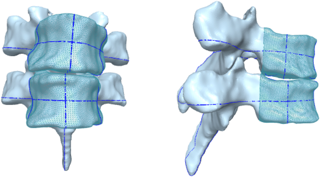
3D renderings of vertebral levels T4 and T5 from oblique coronal and sagittal views, demonstrating Type II mechanics flexion: 10.2°, rotation: −2.4°, side-bending −5.5°. The wireframe region represents the separated vertebral body. The blue lines represent the symmetry planes of the vertebra.
3D renderings of vertebral levels T3 and T4 from oblique coronal and sagittal views, demonstrating non-Fryette’s mechanics flexion: 2.4°, rotation: −2.5°, side-bending −3.9°. The wireframe region represents the separated vertebral body. The blue lines represent the symmetry planes of the vertebra.
With these definitions in place, the algorithm and calculations described above was performed on 82 CT scans containing 953 thoracic and lumbar vertebrae. Exclusion criteria consisted of spinal pathologies that could impede vertebral movement specifically, Grades II–IV osteophtyes [19], and visible vertebral and spinal deformities. The evaluation of these criteria was conducted by medical students utilizing the available 3D models within the dataset. Similarly, vertebrae for whom any of the symmetry planes could not be accurately calculated were similarly omitted from analysis. Finally, any vertebrae that did not have a sequential vertebral level below, whether due to that level being removed or the CT scan not including that level, were excluded from analysis as well.
Statistical analysis was performed utilizing one-sample probability z-scoring with an ∝=0.05, and the null hypothesis was set to Fryette’s mechanics occurring by chance with a probability of occurrence of 50 %. Because z-scoring assumes independence among each datapoint, each vertebral level was tested separately to ensure independence across the z-scores. The entirety of this project, including programming, data review, and statistical analysis, was performed between July 2021 and July 2023.
Results
For 953 thoracic and lumbar vertebrae from 82 CT scans, 128 were noted to have pathologies severe enough to disrupt normal vertebral motion and were omitted from the analysis. One or more symmetry planes were not accurately calculated for 120 vertebrae, the total excluded being 248. Of the 705 remaining, 531 were sequential-providing datapoints with three angles defining flexion, extension, rotation, and side-bending relative to the vertebral level below.
The averages and standard deviation of these angular positionings for each vertebral level are displayed in Table 1. Average flexion/extension ranges from −21.92° (L5) to 5.45° (T6). Rotation exhibits an average ranging from −1.19° (T4) to 0.60° (T11), while average side-bending ranged from −1.68° (T5) to 2.46° (T3).
The presentation of vertebral levels along with their average orientation and standard deviation, expressed in degrees relative to the vertebra immediately below, corresponding to specific planes of motion in Fryette’s theory.
| Vertebral level | Flexion/extension | Axial rotation | Side-bending |
|---|---|---|---|
| T1 | 0.01 ± 5.55 | 0.26 ± 1.12 | 0.17 ± 1.97 |
| T2 | 3.79 ± 2.29 | 0.55 ± 1.60 | 1.46 ± 1.34 |
| T3 | 3.66 ± 2.98 | −0.72 ± 1.00 | 2.46 ± 1.55 |
| T4 | 4.65 ± 2.55 | −1.19 ± 1.42 | 0.42 ± 1.92 |
| T5 | 5.42 ± 2.30 | −0.79 ± 0.90 | −1.68 ± 2.06 |
| T6 | 5.45 ± 3.37 | −0.31 ± 0.81 | −1.46 ± 1.71 |
| T7 | 3.93 ± 1.90 | 0.37 ± 1.06 | −1.14 ± 1.40 |
| T8 | 1.66 ± 1.94 | 0.38 ± 0.94 | 0.27 ± 1.25 |
| T9 | 1.69 ± 2.35 | 0.01 ± 1.14 | 0.07 ± 1.37 |
| T10 | 2.03 ± 3.22 | 0.31 ± 1.09 | 0.34 ± 1.24 |
| T11 | 3.68 ± 4.17 | 0.60 ± 1.33 | 0.34 ± 1.38 |
| T12 | 0.75 ± 3.22 | 0.37 ± 0.93 | 0.13 ± 1.36 |
| L1 | −1.08 ± 3.07 | 0.20 ± 1.04 | −0.25 ± 1.51 |
| L2 | −4.79 ± 3.70 | 0.26 ± 1.39 | 0.56 ± 1.85 |
| L3 | −8.60 ± 3.90 | 0.18 ± 1.33 | 0.61 ± 1.97 |
| L4 | −15.58 ± 4.58 | −0.52 ± 1.60 | 0.24 ± 2.04 |
| L5 | −21.92 ± 4.70 | −0.46 ± 0.95 | −0.86 ± 2.40 |
A total of 302 vertebrae demonstrated orientations consistent with motions derived by Fryette’s mechanics (166 Type II, 136 Type I). This demonstrates that 56.9 % (p=0.0014, power=89 %) of vertebrae successfully analyzed demonstrated positions primed for Fryette’s mechanics. Levels that demonstrated statistical significance consisted of T5 (p=0, power=99 %), T6 (p=0.0023, power=77 %), T7 (p=0.041, power=46 %), and T10 (p=0.017, power=60 %) (Table 2).
One-sample proportional z-scoring performed on each individual level.
| Vertebral levels | Total | % Exhibiting Fryette | z-score | p-Value | Power |
|---|---|---|---|---|---|
| T1 | 19 | 57.89 | 0.6970 | 0.4858 | 0.099 |
| T2 | 23 | 52.17 | 0.2087 | 0.8347 | 0.040 |
| T3 | 25 | 60.00 | 1.0206 | 0.3074 | 0.163 |
| T4 | 27 | 55.56 | 0.5809 | 0.5613 | 0.082 |
| T5 | 24 | 87.50 | 5.5549 | 0 | 0.995 |
| T6 | 25 | 76.00 | 3.0439 | 0.0023 | 0.773 |
| T7 | 23 | 69.57 | 2.0392 | 0.0414 | 0.464 |
| T8 | 23 | 43.48 | −0.6309 | 0.5281 | 0.089 |
| T9 | 29 | 44.83 | −0.5601 | 0.5754 | 0.079 |
| T10 | 30 | 70.00 | 2.3905 | 0.0168 | 0.600 |
| T11 | 46 | 54.35 | 0.5920 | 0.5538 | 0.085 |
| T12 | 53 | 56.60 | 0.9700 | 0.3320 | 0.157 |
| L1 | 53 | 50.94 | 0.1375 | 0.8907 | 0.034 |
| L2 | 49 | 42.86 | −1.0104 | 0.3123 | 0.166 |
| L3 | 44 | 61.36 | 1.5481 | 0.1216 | 0.321 |
| L4 | 30 | 46.67 | −0.3660 | 0.7144 | 0.055 |
| L5 | 8 | 62.50 | 0.7303 | 0.4652 | 0.098 |
-
The total number of vertebrae in each level is shown in column 2. Column 3 demonstrates the percentage exhibiting Fryette-compatible positioning. z-scores and p values are shown in column 4 and 5, respectively. p values<0.05 were considered statistically significant and are highlighted. Power analysis is shown in column 6.
Discussion
Our study sought to investigate whether static vertebrae captured in CT scans exhibit orientations aligning with Fryette’s mechanics, a foundational concept in osteopathic medicine for understanding spinal motion. The findings suggest a nuanced view of spinal mechanics, with a statistically significant portion of vertebrae demonstrating orientations compatible with Fryette’s mechanics, albeit not overwhelmingly so. These results underscore the complexity of spinal movement and the potential influence of static vertebral positioning on dynamic motion.
Fryette’s laws of spinal motion have been a cornerstone of osteopathic philosophy and practice. However, the applicability of these principles to understanding and diagnosing spinal pathology in a clinical setting has been debated, particularly in light of modern imaging techniques. Our study contributes to this ongoing discourse by providing empirical data on the static orientations of vertebrae in relation to Fryette’s mechanics. With 56.9 % (p=0.0014) of the vertebrae analyzed showing orientations consistent with Fryette’s descriptions, our findings lend partial statistical support but very limited clinical support because this occurs a little more often than chance.
Levels T5–T7 and T10 displayed a notable propensity for being primed for Fryette’s motion, although the calculated power for these (except for T5) was suboptimal (<80 %). Further studies should seek to have a larger sample size at these vertebral levels. These validation studies may pave the way for utilizing CT imaging in diagnosing somatic dysfunction, presenting a potential nonmanual approach in osteopathic assessments.
Limitations
This study operated under the assumption that movements associated with coupled vertebral motion were small enough not to significantly affect the coupled directionality. However, considering the narrow ranges, particularly in the average rotational position of vertebrae, even small movements may have substantial implications. Future investigations employing dynamic imaging methods are warranted to unravel the impact of these subtle movements.
Another consequential assumption limiting our study is the selection of a neutral range for each individual vertebra rather than treating the entire spine, and vertebrae therein, as neutral. While focusing on individual vertebral segments aligns with the study’s objectives, it introduces a potential divergence from osteopathic principles that often consider the spine as a unified entity. Future research could explore the implications of this approach on diagnostic accuracy and treatment efficacy. Additionally, the neutral range selection between −3 and 3° holds significance. While various ranges were initially explored, none demonstrated statistical or clinical superiority over this specific range. Future studies may endeavor to identify a novel range that could yield more robust and statistically significant results. This could involve exploring an overlapping range, a unidirectional range, or a range tailored to each vertebra.
The dataset’s original purpose, not tailored for our study, introduces limitations, including the likely inclusion of pathological specimens not excluded by our criteria. Additionally, exclusions were based on features seen in 3D models, which differs from radiologists who would make exclusions based on CT scans. Future studies should involve radiologists in selecting datasets specifically designed for this purpose, free of pertinent pathology.
This study also suffers from the positioning of the patients in the CT scans, with studies suggesting that coupled vertebral motion is affected by supine measurements vs. standing measurments [5]. In relation to Fryette’s mechanics, we should prioritize performing studies that utilize radiography that enables standing measurements.
Conclusions
Although VERSE`20 was designed for alternative purposes, we believe that large open-source datasets designed for machine learning provides an untapped reservoir of pertinent data that researchers should begin adapting to other research questions.
This research, which benefits from speed and quantity, was able to analyze the orientation of a large number of vertebrae and introduces one of very few algorithms that requires no manual input to calculate 3D angular orientation of vertebrae.
This research is an exciting look at how modern technologies and methods can be utilized to test and improve upon past osteopathic theories. In the case of Fryette’s mechanics, our analysis demonstrates that the orientation of stationary vertebra in CT scans do align with Fryette’s descriptions statistically, though not often. Further motion-based studies should seek to validate Fryette’s mechanics to confirm its validity of use in clinical practice. These studies should consider standing dynamic motion of vertebrae, with special attention to regions T5 through T7 and T10.
Acknowledgments
During the preparation of this work the authors used ChatGPT 3.5 to improve language used throughout the text, to optimize understanding. After using this service, the authors reviewed and edited the content as needed and take full responsibility for the content of the publication. No completely original material was generated or utilized, only revisionary language was utilized in this paper.
-
Research ethics: This research was deemed exempt from the Institutional Review Board review process. BURRELL IRB# 0110_2023.
-
Informed consent: Not applicable.
-
Author contributions: Dillon Haughton provided substantial contributions to conception, logistics, data acquisition, data analysis, and data conceptualization. Emily Barr drafted the abstract and supporting images. Akhil Gupta provided programming language support. Walker Toohey provided data method investigation, and scientific research adaptability. Adrienne Kania provided insight into osteopathic phenomena, research fundamentals, mentorship, and guidance in completing this project.
-
Competing interests: None declared.
-
Research funding: None declared.
-
Data availability: The raw data can be obtained from the open-sourced verse20 dataset located at https://github.com/anjany/verse.
References
1. Cook, C, Showalter, C. A survey on the importance of lumbar coupling biomechanics in physiotherapy practice. Man Ther 2004;9:164–72. https://doi.org/10.1016/j.math.2004.03.003.Suche in Google Scholar PubMed
2. Fryette, HM. Principles of osteopathic technic. Indianapolis, IN: Academy of Applied Osteopathy; 1954.Suche in Google Scholar
3. Seffinger, MA, Hruby, RJ, Willard, FH, Licciardone, J, Kuchera, WA, Rey, M, et al.. Foundations of osteopathic medicine: philosophy, science, clinical applications and research, 4th ed. Philadelphia, PA: Wolters Kluwer; 2018:576–608 pp.Suche in Google Scholar
4. Ochia, RS, Inoue, N, Renner, SM, Lorenz, EP, Lim, TH, Andersson, GBJ, et al.. Three-dimensional in vivo measurement of lumbar spine segmental motion. Spine 2006;31:2073–8. https://doi.org/10.1097/01.brs.0000231435.55842.9e.Suche in Google Scholar PubMed
5. Haughton, VM, Rogers, B, Meyerand, ME, Resnick, DK. Measuring the axial rotation of lumbar vertebrae in vivo with MR imaging. AJNR Am J Neuroradiol 2002;23:1110–6.Suche in Google Scholar
6. Pearcy, MJ. Stereo radiography of lumbar spine motion. Acta Orthop Scand Suppl 1985;212:1–45. https://doi.org/10.3109/17453678509154154.Suche in Google Scholar PubMed
7. Moon, OK, Kim, SH, Lee, SB, An, HJ, Kim, BK, Kim, NJ, et al.. Thoracic coupled motions of Korean men in good health in their 20s. J Phys Ther Sci 2014;26:87–91. https://doi.org/10.1589/jpts.26.87.Suche in Google Scholar PubMed PubMed Central
8. Legaspi, O, Edmond, SL. Does the evidence support the existence of lumbar spine coupled motion? A critical review of the literature. J Orthop Sports Phys Ther 2007;37:169–78. https://doi.org/10.2519/jospt.2007.2300.Suche in Google Scholar PubMed
9. Sekuboyina, A, Husseini, ME, Bayat, A, Löffler, M, Liebl, H, Li, H, et al.. VerSe: a vertebrae labelling and segmentation benchmark for multi-detector CT images. Med Image Anal 2021;73:102166. https://doi.org/10.1016/j.media.2021.102166.Suche in Google Scholar PubMed
10. Löffler, MT, Sekuboyina, A, Jacob, A, Grau, AL, Scharr, A, El Husseini, M, et al.. A vertebral segmentation dataset with fracture grading. Radiol Artif Intell 2020;2:e190138. Published 2020 Jul 29. https://doi.org/10.1148/ryai.2020190138.Suche in Google Scholar PubMed PubMed Central
11. Liebl, H, Schinz, D, Sekuboyina, A, Malagutti, L, Löffler, MT, Bayat, A, et al.. A computed tomography vertebral segmentation dataset with anatomical variations and multi-vendor scanner data. Sci Data 2021;8:284. Published 2021 Oct 28. https://doi.org/10.1038/s41597-021-01060-0.Suche in Google Scholar PubMed PubMed Central
12. Larobina, M, Murino, L. Medical image file formats. J Digit Imag 2014;27:200–6. https://doi.org/10.1007/s10278-013-9657-9.Suche in Google Scholar PubMed PubMed Central
13. Fedorov, A, Beichel, R, Kalpathy-Cramer, J, Finet, J, Fillion-Robin, JC, Pujol, S, et al.. 3D slicer as an image computing platform for the Quantitative Imaging Network. MRI 2012;30:1323–41. https://doi.org/10.1016/j.mri.2012.05.001.Suche in Google Scholar PubMed PubMed Central
14. Cicconet, M, Hildebrand, DG, Elliott, H. Finding mirror symmetry via registration and optimal symmetric pairwise assignment of curves. arXiv (Cornell University); January 2016. https://doi.org/10.48550/arxiv.1611.05971.Suche in Google Scholar
15. Vrtovec, T, Pernus, F, Likar, B. A symmetry-based method for the determination of vertebral rotation in 3D. Med Image Comput Comput Assist Interv 2008;11:942–50. https://doi.org/10.1007/978-3-540-85988-8_112.Suche in Google Scholar PubMed
16. Vrtovec, T, Pernus, F, Likar, B. Determination of axial vertebral rotation in MR images: comparison of four manual and a computerized method. Eur Spine J 2010;19:774–81. https://doi.org/10.1007/s00586-010-1340-y.Suche in Google Scholar PubMed PubMed Central
17. Vrtovec, T, Pernus, F, Likar, B. A review of methods for quantitative evaluation of axial vertebral rotation. Eur Spine J 2009;18:1079–90. https://doi.org/10.1007/s00586-009-0914-z.Suche in Google Scholar PubMed PubMed Central
18. Di Angelo, L, Di Stefano, P. A new method for the automatic identification of the dimensional features of vertebrae. Comput Methods Programs Biomed 2015;121:36–48. https://doi.org/10.1016/j.cmpb.2015.04.003.Suche in Google Scholar PubMed
19. Nathan, H. Osteophytes of the vertebral column. J Bone Joint Surg 1962;44:243–68. https://doi.org/10.2106/00004623-196244020-00003.Suche in Google Scholar
© 2024 the author(s), published by De Gruyter, Berlin/Boston
This work is licensed under the Creative Commons Attribution 4.0 International License.
Artikel in diesem Heft
- Frontmatter
- Medical Education
- Original Article
- Assessing nutrition literacy and nutrition counseling proficiency following an interdisciplinary culinary medicine elective
- Neuromusculoskeletal Medicine (OMT)
- Original Article
- Investigating Fryette’s mechanics in computed tomography scans: an analysis of vertebrae spinal physiology using open-sourced datasets and three-dimensional vertebral orientation
- Review Article
- Effect of manual manipulation on mechanical gait parameters
- Obstetrics and Gynecology
- Original Article
- The impact of prepregnancy body mass index on pregnancy and neonatal outcomes
- Public Health and Primary Care
- Original Article
- Associations of clinical personnel characteristics and telemedicine practices
- Clinical Image
- Davener’s dermatosis: a unique presentation of frictional hypermelanosis
- Letters to the Editor
- Fostering a research culture in osteopathic medical education
- Response to “Fostering a research culture in osteopathic medical education”
- Corrigendum
- Corrigendum to: A superficial dissection approach to the sphenopalatine (pterygopalatine) ganglion to emphasize osteopathic clinical relevance