Analysis of Internal Cracks in Continuous Casting Slabs with Soft Reduction
-
Bo Wang
 ,
Chao Xiao
,
Chao Xiao

Abstract
The formation of internal cracks in continuous casting slabs is mainly attributed to the strain status and microsegregation near the solidifying front of the slabs. By analyzing the internal cracks of medium carbon microalloy steel, the obtained conclusions are that C, P, S, etc. enrich in dendrites and exist in grain boundaries, but these are just the internal causes, and the root cracking causes the tensile stress of solidification front. When the slab passes through the straightening segments, the liquid core thickness is large, and the liquid steel in the space of columnar crystals is not completely frozen. Therefore, the reduction effect of rollers results in the strain of solidification front exceeding the critical value. However, the corresponding strain in the arc and horizontal segments does not exceed this critical value, so the solidification front in the straightening segments would be much easy to crack. The statistics analysis shows that after soft reduction and straightening process are separately carried out, the occurrence rate of intermediate cracks is reduced by 41.3%.
Introduction
Owing to its inherent advantages of low cost, high yield, flexibility of operation and ability to achieve a high-quality cast product, the continuous casting process has been adopted worldwide by the steel industry [1]. In recent years, with ever increasingly stringent requirements for the product quality, some problems have occurred. Due to higher casting speeds and larger reductions, internal cracks can easily occur [2]. Internal cracks have been recognized as a problem in the continuous casting of steel.
The formation of internal cracks in continuous casting slab was mainly attributed to the strain status and microsegregation near the solidifying front of slabs. Internal cracks always occur in a brittle temperature range by thermal and mechanical deformation during continuous casting process [3] and the mechanical properties can be characterized by four characteristic temperatures: zero strength temperature (ZST), zero ductility temperature (ZDT), liquid impenetrable temperature (LIT) and liquidus temperature (TL) [4].
Many previous studies have reported that internal cracks often occur between ZST and ZDT [5–7]. Shin et al. [8] reported that the solid fraction at ZST corresponded to the range of 0.6–0.7 and ZDT corresponded to 1.0. Nakagawa et al. [9] reported that the solid fractions at ZST and ZDT were 0.75 and 0.98, respectively, in high carbon steels. However, in order to improve the internal quality of continuous casting steel, soft reduction process was carried out. But with the decrease of quantity and dimension of center segregation area and center porosity decrease, internal cracks located between the surface and the centerlines of slabs are observed [10]. Kim et al. [11] built a two-dimensional transient-coupled thermoelastoplastic finite element model and they found that a large tensile stress developed in the internal region of the flange tip from the intermediate stage of casting, which in turn could cause internal cracking in the flange tip region. Wang et al. [12] calculated the temperature distribution, the stress and strain states in the billet and the results indicated that tensile stresses could develop in the mushy zone during soft reduction and the equivalent strain nearby the ZDT increased with the decreasing solid fraction. Mintz [13] investigated the influence of N, V, Ti and the residuals, Cu, Sn, S and P, on the hot ductility of steel. Han et al. [14] explored the effect of impurity elements, such as P and S. Their results showed that the freezing temperature of the interdendritic liquid significantly decreased, thus obviously decreasing the deformation-resistant ability of the solidifying front. Accordingly, microsegregation is also responsible for the formation of the internal cracks.
Due to the high incidence of internal cracks of slab during soft reduction, therefore, in order to avoid and minimize internal cracks, the effects of the strain status at solidifying front and the chemical composition of liquid steel on the internal cracks are studied in this paper so as to avoid and minimize internal cracks.
Experimental procedure
In order to analyze the morphology of internal cracks, a series of experiments with a Q345R slab specimen were performed and the slab thickness was 220 mm. Table 1 shows the chemical composition of the material. Figure 1 displays the macroscopic feature of internal cracks in a continuous casting slab. The count showed that all internal cracks were present to the inner arc of continuous casting slab and with irregular shapes. The distribution of internal cracks was relatively concentrated and 80–93 mm far from the surface. It was also observed that the length of internal cracks was 6–20 mm.
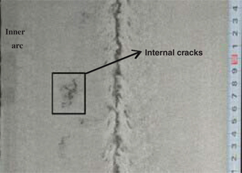
Macroscopic feature of internal cracks.
Chemical composition of the workpiece (wt%).
| Steel | C | Si | Mn | P | S | Cr | Mo | Ni |
| Q345R | 0.1641 | 0.2358 | 1.3688 | 0.0142 | 0.0075 | 0.09 | 0.01 | 0.003 |
Macroscopic feature of internal cracks
For the convenience of the analysis, three complete internal cracks were cut from the continuous casting slab labeled as 1#, 2# and 3#. The schematic of the experiment was as shown in Figure 2.

Schematic diagram of internal cracks.
In order to investigate the relation between columnar crystal, equiaxed crystal and internal cracks, three samples were etched with picric acid in an aqueous phase as shown in Figure 3. It could be seen that the shapes of all those internal cracks were similar and the position was located at the end of the columnar crystal zone. The extension direction of internal cracks was perpendicular to the growth direction of secondary dendrite. Meanwhile, internal cracks terminated in the juncture of the columnar and equiaxial crystal zones. Several internal cracks were parallelled to each other and the length was almost the same in the fracture area.
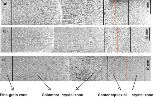
Morphology of internal cracks etched with picric acid: (a) 1#, (b) 2# and (c) 3#.
Fracture morphology of internal cracks
Figure 4 shows the fracture morphology of internal cracks. The fracture morphology of three internal cracks was similar. However, because the depth of internal cracks was very shallow, cracks tore during the cracking process. Therefore, the fracture of local cracks was plastic. As a whole, there were few dimples in the zone of cracking deformation. There was some liquid steel in this area during crack formation. It can be considered that internal cracks were formed in the liquid–solid phase region.

SEM images of the fracture surface: (a) 1#, (b) 2# and (c) 3#.
Element distribution
Figure 5 shows the solute distribution during the continuous casting process. It was observed that there was a high concentration of solute elements in the temperature range of ZDT to LIT, especially some easy-segregated elements, such as P and S. These solute elements were easy to form inclusions at the grain boundary, and high temperature strength and hot ductility were greatly reduced, leading to intergranular fracture.

Schematic diagram of solute distribution during continuous casting process.
Figure 6 shows the line scanning images of internal cracks. It was observed that the results from three internal cracks were consistent with each other. C, P and S had a trend to enrich in the cracked area, especially that P and S were quite serious.
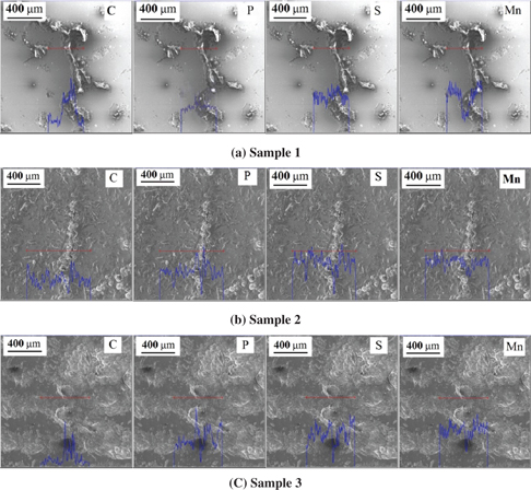
LSM images of C, P, S and Mn at internal cracks: (a) 1#, (b) 2# and (c) 3#.
Finite element simulation
The interdendritic segregation is merely the internal cause for cracking. It just reduces the tensile strength of solidifying front and makes cracks easy to occur. The root acting cracking cause is the tensile stress of solidification front. In the continuous casting process, the factors such as bulging, unbending or straightening can result in tensile strains near the solidifying front of the slab. Therefore, a 3D non-linear finite element model was established to analyze the strain states during soft reduction.
Model description
The size of cross section is 220 mm × 2,080 mm. In order to save calculation time and calculation resource, the finite element model was assumed to be symmetric about its mid-plane. The finite model was established as the 1/2 of entity in width direction. Rollers were created as analytical rigid bodies. Figure 7 shows the soft reduction process.
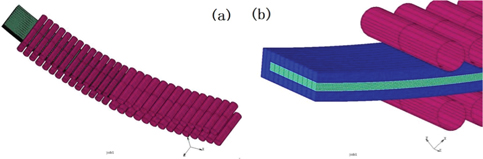
Schematic diagram of soft reduction.
The experimental results showed that internal cracks were easily formed in the zone with the solid fraction from 0.2 to 0.5, namely at No. 7 and No. 8 segments. Soft reduction schedules are as shown in Table 2. The thermal mechanical was also analyzed at arc segments (5# and 6#) and horizontal segments (9# and 10#).
Detailed soft reduction schedules of simulation.
| No. | Steel | Reduction amount/mm | fs | Reduction amount of each sector segment/mm | |||||
| 5# | 6# | 7# | 8# | 9# | 10# | ||||
| 1 | Q345R | 3.5 | 0.1–0.3 | 2.6 | 1.5 | ||||
| 2 | Q345R | 5.0 | 0.1–0.3 | 4.2 | 2.8 | ||||
| 3 | Q345R | 6.5 | 0.1–0.3 | 5.1 | 3.4 | ||||
| 4 | Q345R | 3.5 | 0.2–0.5 | 1.4 | 2.8 | ||||
| 5 | Q345R | 5.0 | 0.2–0.5 | 2.8 | 4.2 | ||||
| 6 | Q345R | 6.5 | 0.2–0.5 | 3.4 | 5.1 | ||||
| 7 | Q345R | No | 0.2–0.5 | ||||||
| 8 | Q345R | 3.5 | 0.5–0.9 | 2.6 | 1.5 | ||||
| 9 | Q345R | 5.0 | 0.5–0.9 | 4.2 | 2.8 | ||||
| 10 | Q345R | 6.5 | 0.5–0.9 | 5.1 | 3.4 | ||||
Finite element analysis
Hiebler et al. [15] investigated the relation between carbon content and critical strain, and it was found that the critical strain of medium carbon alloy steel was 0.4% to 0.5%. The critical strain was assumed as 0.4% in this paper. Figure 8 displays the strain of solidifying front with different soft reduction amounts in the inner arc. It was observed that the strain value was no more than 0.4% no matter how much the weight was reduced during segments 5–6 and 9–10. However, when the slab passed through the straightening segments (7# and 8#), the strain exceeded the critical value.

Strain of solidifying front at different segments: (a) segments 5 and 6; (b) segments 7 and 8 and (c) segments 9 and 10.
Discussion
By analyzing the internal cracks of medium carbon microalloy steel, the obtained conclusions are that C, P, S, etc. enrich in dendrites and exist in grain boundaries, but these are just the internal causes, and the root cracking cause is the tensile stress of solidification front. When slab passes through the straightening segments with soft reduction, the tensile stress was produced in the inner arc under the effects of straightening and soft reduction in the direction of casting speed. Under the interactions, the solidified dendrite was cracking suddenly with the increase of the spacing between dendrites in the liquid–solid phase region. Because the liquid steel was blocked by the prosperous secondary dendrite, cracks were left. However, the corresponding strain in the arc and horizontal segments do not exceed this critical value, so the solidification front in the straightening segments would be much easy to crack. The statistics analysis shows that after soft reduction and straightening process are separately carried out, the occurrence rate of intermediate cracks is reduced by 41.3%.
Conclusions
All internal cracks were present to the inner arc of continuous casting slab and with irregular shapes. The distribution of internal cracks was relatively concentrated and 80–93 mm far from surface.
C, P and S had trend to enrich in the cracked area, especially P and S were quite serious. These solute elements were easy to form inclusions at the grain boundary, and high temperature strength and hot ductility were greatly reduced, leading to intergranular fracture.
The reduction effect of rollers results in the strain of solidification front exceeding the critical value; however, the corresponding strain in the arc and horizontal segments does not exceed this critical value, so the solidification front in the straightening segments would be much easy to crack.
The statistics analysis showed that after soft reduction and straightening process are separately carried out, the occurrence rate of internal cracks is reduced by 41.3%.
Acknowledgments
The authors gratefully express their appreciation to National Natural Science Fund of China (U1360201) and the National High Technology Research and Development Program of China (863 Program) No. 2012AA03A505 for sponsoring this work. Sincere gratitude and appreciation should be expressed to Professor Jiongming Zhang for his careful guidance.
References
[1] J. K.Brimacombe, Metall. Trans. B., 24 (1993) 917–935.Search in Google Scholar
[2] K. H.Kim, T. J.Yeo, ISIJ Int., 38 (1998) 1093–1099.Search in Google Scholar
[3] F.Weinberg, Metall. Trans. B., 10 (1979) 513–522.Search in Google Scholar
[4] K. H.Kim, T. J.Yeo, K. H.Oh, L. N.Dong, ISIJ Int., 36 (1996) 284–289.Search in Google Scholar
[5] A.Yamanaka, K.Okamura, K.Nakajima, Ironmaking Steelmaking, 22 (1995) 508–512.Search in Google Scholar
[6] D. J.Seol, Y. M.Won, K. H.Oh, Y. C.Shin, C. H.Yim, ISIJ Int., 40 (2000) 356–363.Search in Google Scholar
[7] Y. M.Won, B. G.Thomas.Metall. Mater. Trans. A., 32 (2001) 1755–1767.Search in Google Scholar
[8] G.Shin, T.Kajitani, T.Suzuki, T.Umeda, Tetsu-to-Hagane, 78 (1992) 587–593.Search in Google Scholar
[9] T.Nakagawa, T.Umeda, J.Murata, Y.Kamimura, ISIJ Int., 35 (1995) 723–729.Search in Google Scholar
[10] X. B.Li, H.Hua, Z. Y.Tang, J. C.He, Metall. Mater., 19 (2012) 21–29.Search in Google Scholar
[11] K.Kim, H. N.Han, T.Yeo, Y.Lee, K. H.Oh, D. N.Lee, Ironmaking Steelmaking, 24 (1997) 249–256.Search in Google Scholar
[12] W. J.Wang, L. X.Ning, R.Bülte, W.Blech, Miner. Metall. Mater., 15 (2008) 114–119.Search in Google Scholar
[13] B.Mintz, ISIJ Int., 39 (1999) 833–855.Search in Google Scholar
[14] Z.Han, K.Cai, B.Liu.ISIJ Int., 41 (2001) 1473–1480.Search in Google Scholar
[15] H.Hiebler, J.Zirngast, C.Bernhard, M. M.Wolf, Steelmaking Conf., 77 (1994) 405–416.Search in Google Scholar
©2016 by De Gruyter
This article is distributed under the terms of the Creative Commons Attribution Non-Commercial License, which permits unrestricted non-commercial use, distribution, and reproduction in any medium, provided the original work is properly cited.
Articles in the same Issue
- Frontmatter
- Research Articles
- Long-Lasting Phosphorescent Properties of Tb3+ Doped ZnO–P2O5–SiO2 Glasses
- The Effects of Mechanical Properties on Fatigue Behavior of ECAPed AA7075
- An Effective Approach Based on Response Surface Methodology for Predicting Friction Welding Parameters
- Small Two-Bar Specimen Creep Testing of Grade P91 Steel at 650°C
- Estimating Electrical Conductivities of CaO-MgO-Al2O3-SiO2 Using Ion-Oxygen Parameter
- Non-Arrhenius Viscosity Models for Molten Silicate Slags with Constant Pre-Exponential Parameter: A Comparison to Arrhenius Model
- Analysis of Internal Cracks in Continuous Casting Slabs with Soft Reduction
- Effects of Sodium Citrate on the Ammonium Sulfate Recycled Leaching of Low-Grade Zinc Oxide Ores
- Finite Element Creep Damage Analyses and Life Prediction of P91 Pipe Containing Local Wall Thinning Defect
- A Comparative Study on Johnson Cook, Modified Zerilli–Armstrong and Arrhenius-Type Constitutive Models to Predict High-Temperature Flow Behavior of Ti–6Al–4V Alloy in α + β Phase
- Carbothermic Reduction of Titanium-Bearing Blast Furnace Slag
- Microstructure and Mechanical Property of 12Cr Oxide Dispersion Strengthened Steel
- Constitutive Modeling for Flow Stress Behavior of Nimonic 80A Superalloy During Hot Deformation Process