Investigation into the effect of the angle of dual slots on an air flow field in melt blowing via numerical simulation
-
Xin Sanfa


Abstract
The effect of the angle of dual slots on an air flow field in melt blowing was researched via numerical simulation. Through establishing the geometric model of air flow field in melt blowing with dual slots, meshing, designating the boundary conditions and their parameters and numerical simulation, the result illustrates the influence of the angle of dual slots on the variations of air velocity, pressure and temperature distributions. Higher peak values of air velocity, pressure and temperature are obtained with larger angles of dual slots near the die, while only a few differences of these parameters are detected away from the die. Our results demonstrate the angle of 70° is the appropriate one that can produce the finest fibers.
1 Introduction
Melt blowing (MB) is a single-step process used to generate fibers or their nonwoven mats from a polymer melt. In this process, an air jet is main cause that changes the polymer melt into the fibers, only a few reports related to the form or the distribution state of the air jet have been reported (1–5). In MB, the symmetrical air jets of dual slots are common, which has been used widely in MB theory (6–10) and commercial production (11–13). The characteristic of MB with dual slots is as follows. When the polymer resin materials are extruded from the fine capillary, they are impacted upon by two hot air jets of high-velocity immediately. The polymer melt is attenuated into the fibers quickly and laid on the collection screen. In MB with dual slots, the angle of dual slots is an important parameter, which has extreme effects on the fiber diameter and the quality of fiber-web. In Wente’s study it was suggested that the smaller angle of dual slots led to finer fibers, easier fiber entanglement and accompanying worse fibrous webs, and vice versa. However, the bigger the angle of dual slots was and the thicker the fiber diameter was, the smaller the cohesive probability between fibers and the better the quality of fiber-web was. Up to now, the angle of dual slots in most of the reported theoretical research and MB practice was 60° without interpretation.
In this paper, we focus on the relationship between the angle of dual slots and the parameters of an air flow field. Mainly, the study examines the effect of the angle of dual slots on air flow field. Finally, the appropriate angle was obtained to be used for the finer fibers. By the numerical simulation method, the air flow fields are simulated first, then the results are analyzed by comparison.
2 Numerical procedures
A similar die configuration used by Harpham and Shambaugh (HS) (see Figure 1) (15) is also employed in our simulation work. For the simulation, as with the HS experiments, the head width between dual slots is set at a=2.02×10⁻³ m, the slot widths of the die is set at e=0.56×10⁻³ m and the slot height is set at h=5.00×10⁻³ m. The angle of dual slots are set at 0°, 20°, 40°, 50°, 60°, 70°, 80°, 100° and 120°, respectively. In the following, the angle of 60° is an example to show the numerical procedures.
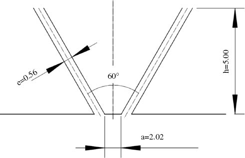
Schematic of HS die.
The space under the die is considered as the computational domain. To simplify computation or calculation, the calculation domain was half of the total air flow field (see Figure 2). The dimensions of the computational domain size are Lx=-5~100×10-3 m and Ly=0~15×10-3 m.

Schematic of half of the main computational domain.
The boundary conditions and their parameters are designated by the following. The inlet of the calculation domain (the AB line) is defined as a “pressure inlet” with an absolute pressure of 1.4 atm and the total temperature is 543 K. The outlets of the computational domain (the EF line, GF line) are defined as “pressure outlets” with atmospheric conditions (the pressure is 1.0 atm and the temperature is 300 K). The boundary conditions of “symmetry” are used at the symmetric line (the OG line) of the flow field. All other boundaries (the AD line, the OD line, the BC line and the CE line) are assigned as a non-slip wall with a default setting. k-ε turbulence model is selected as a turbulence calculation, and the turbulence parameters Ce1 and Ce2 are adopted as 1.24 and 2.05, respectively, as used by Krutka et al. (15). The inlet and outlet boundary parameters are also based on the study of Krutka et al. (15) who performed MB experiments to verify these parameters. Finally, we set the turbulence specifications of the inlet boundary as an intensity of 10% and the hydraulic diameter the same as the slot width. The turbulence intensity is 10% and the length scale is 10 mm at the pressure outlets.
The commercial software FLUENT 6.3 (Fluent Inc., USA) is used for simulation in this article.
3 Simulation results and discussions
3.1 Air velocity distribution along the centerline
Figure 3 shows the effect of the angle between two slots on the velocity distribution at the centerline. Figure 3A shows the whole curves. Figure 3B shows a part of the curves closer to the die head and Figure 3C displays the part of the curves further from the die head. As shown in Figure 3A, all the curves had a similar profile, which is in line with the literature (15). As can be seen, the closer to the die head, the larger the angle, and the higher the peak value of the air velocity (see Figure 3B). A highest peak value appears when the angle is 120°. And the curves of 100°, 80° and 70° also exhibit similar peak values. In the distance further from the die head, the closer the angle is to 70°, the higher the air velocity is (see Figure 3C). Obviously, a highest velocity value is observed in the curve of 70°. The reasons for this phenomenon could be explained as follows. When the angle is smaller than 70°, there appears to be a slight convergence of the two jets with the increasing of the angle value. When the angle is higher than 70°, the increase in the angle value leads to the degree of violent collisions between two air jets. The more violent the collision is, the more the energy consumption is. So, the result suggests that there is the biggest velocity value when the angle is 70°.
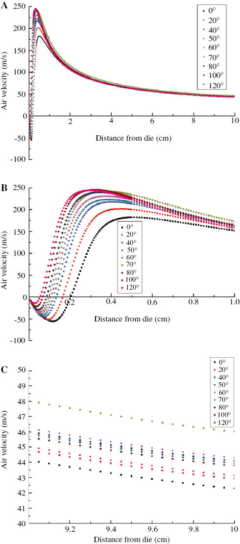
Effect of the angle between two slots on the velocity distribution along the centerline.
(A) The total distribution curves of velocity, (B) the distribution curves of velocity near the die (0–1 cm), and (C) the distribution curves of velocity far from the die (9–10 cm).
Also, Figure 3B shows the development of the initial velocity, which is called “three zones” as mentioned in literature (15). The first zone, which is immediately below the die, exhibits the negative velocity values and less positive velocity values. The second zone, which is further below the die, is a zone where the velocity values are larger than that in the first zone. Finally, the third zone is where the velocity values are larger than that in the front two zones.
In melt blowing, air velocity is the main cause of the fiber attenuation. Therefore, from the point of air velocity, we can infer that the angle of 70° is the appropriate parameter that can produce finer fibers.
3.2 Air pressure distribution along the centerline
Figure 4 illustrates influence of the angle of dual slots on air pressure distributions at the centerline. Figure 4A shows the whole curves. Figure 4B shows part of the curves closer to the die head and Figure 4C shows part of the curves further from the die head. As can be seen, the effect of the angle on air pressure is almost the same as that on the velocity. In the distance closer to the die head, the larger the angle is and the higher the peak value of air pressure is; in the distance further from the die head, the closer the angle is to 70°, the larger the air pressure is. So, there is the highest pressure peak value in the angle of 120° near the die and the largest pressure value in the angle of 70° farthest from the die.

Effect of the angle between two slots on the velocity distribution along the centerline.
(A) The total distribution curves of pressure, (B) the distribution curves of pressure near the die (0–1 cm), and (C) the distribution curves of pressure farthest from the die (9–10 cm).
Our analysis demonstrates that the largest total pressure value is obtained by slots with an angle of 70°. From our previous work (4), although air pressure has no effect on the fiber attenuation directly, air pressure can affect the fiber attenuation through changing the cross-sectional shape of the fiber. The changing degree of the cross-sectional shape will directly affect the contact area between the air jet and fiber. The larger the contact area, the larger the drag force on the fiber. So, from the point of air pressure, we can also infer that the angle of 70° is the appropriate parameter that can generate the finer fibers.
3.3 The temperature distribution along the centerline
Figure 5 gives the profiles of the temperature distributions in different angles of dual slots. Figure 5A shows the whole curves. Figure 5B shows part of the curves closer to the die head and Figure 5C shows part of the curves further from the die head. As can be seen, the effect of the angle on the temperature is similar to that on the air velocity and pressure. In the distance closer to the die head, the larger angles of the dual slots cause the higher peak values of the air temperatures; in the distance further from the die head, the larger angles lead to the lower air temperatures. So, there is the highest temperature peak value in the angle of 120° near the die and the highest temperature value in the angle of 0° farthest from the die.

Effect of the angle between two slots on the temperature distribution along the centerline.
(A) The total distribution curves of temperature, (B) the distribution curves of temperature near the die (0–1 cm), and (C) the distribution curves of temperature farthest from the die (9–10 cm).
We know well that air temperature also has no direct effect on the fiber attenuation. The way that the temperature affects the fiber attenuation is through changing the liquidity of polymer melt. If the polymer melt is easily affected by temperature, the profiles of temperature distribution can help to make the finer fibers. The changes in angles will give rise to the changes in energy dispersion along the centerline. Air energy dispersion does not benefit from the constant temperature along the centerline. From the point of air temperature, we can also infer that the angle of 0° is the appropriate parameter that can manufacture the finer fibers.
From all the simulation results above, we can know that changes in the angle of the dual slots can bring about changes in the velocity, pressure or temperature along the centerline. Although near the die head the peak values of the velocity, pressure and temperature are all at the angle of 120°, yet these peak values and the values in the angle of 70° are almost the same. In the area far from the die head, slots with an angle of 70° could generate the highest velocity, pressure or temperature. In general, we believe that there are the bigger parameter values of air flow field at the angle of 70°.
The formation of air flow is a directly reason for this phenomenon. Air flow field is formed by the interaction of two symmetrical air jets coming from dual slots. Although the mechanism for the interaction between two air jets is complicated, we can obtain the effects of the angle of dual slots on the air flow field from the viewpoint of mechanics. In the following, the velocity is an example to explain how the changes in angles cause the variations of the air flow field.
Each velocity vector can be separated into two components along the perpendicular direction. One component is parallel to the centerline (called the parallel component here) and another component is vertical to the centerline (called the vertical component here). The vertical component is counteracted by the vertical component of another air jet, and is not useful to the total velocity at the centerline directly. So, the parallel component is a vital contributor of the total velocity. The changes in angles lead to the changes in the two components. When the angle is lower than 70°, the increase in the angle benefits the combination of the two jets directly, which increases the velocity at the centerline. When the angle is higher than 70°, the increase in the angle brings about the decreasing of the parallel component and the increasing of the vertical component. Thus, the velocity value decreases at centerline. So, the final result is that the biggest velocity value occurs when the angle is 70°. Similarly, the effect of the angle on the other two parameters of the air flow field (the pressure and the temperature) can be analyzed as above. Similar results can also be obtained. In summary, the biggest pressure and the temperature of air flow field appear at the angle of 70°.
In the fiber attenuation, Bansal and Shambaugh (16) pointed out that more than 96% of the total drop in fiber diameter occurred at 1.5 cm below the die. From the simulation results, we can see easily that in most of the limit of 1.5 cm from the die, bigger parameter values of air flow field are formed when the angle of the slots are 70°. So, we can infer that the MB setup with a slot angle of 70° can manufacture finer fibers. The angle of 70° is the appropriate parameter for finer fibers.
4 Conclusions
In this article, the air flow field along the centerline in MB with dual slots was studied by the numerical simulation method. The conclusions are as follows.
The changes in angle of dual slots can cause the changes in air flow field at the centerline. In the distance closer to the die, the larger angle of slots produce higher peak values of air velocity, pressure and temperature. In the distance farthest from the die, air velocity and pressure of air flow is increasingly rising with the angle approximating to 70°.
The angle of 70° is the appropriate parameter for producing the finer fibers.
References
1. Wang Y, Wang X. Numerical analysis of new modified melt-blowing dies for dual rectangular jets. Polym Eng Sci. 2014;54(1):110–6.10.1002/pen.23536Search in Google Scholar
2. Chung C, Kumar S. Onset of whipping in the melt blowing process. J Non-Newtonian Fluid Mech. 2013;192:37–47.10.1016/j.jnnfm.2012.10.005Search in Google Scholar
3. Tan DH, Herman PK, Janakiraman A, Bates FS, Kumar S, Macosko CW. Influence of laval nozzles on the air flow field in melt blowing apparatus. Chem Eng Sci. 2012;80:342–8.10.1016/j.ces.2012.06.020Search in Google Scholar
4. Xin S, Wang X. Investigation into the characteristic of air pressure field in the melt blowing with dual slots via numerical simulation. Adv Mater Res. 2012;538–41:804–9.10.4028/www.scientific.net/AMR.538-541.804Search in Google Scholar
5. Uyttendaele MAJ, Shambaugh RL. The flow field of annular jets at moderate Reynolds numbers. Ind Eng Chem Res. 1989;28(11):1735–40.10.1021/ie00095a027Search in Google Scholar
6. Xie S, Zeng Y. Turbulent air flow field and fiber whipping motion in the melt blowing process: experimental study. Ind Eng Chem Res. 2012;51(14):5346–52.10.1021/ie202938bSearch in Google Scholar
7. Zhou C, Tan DH, Janakiraman AP, Kumar S. Modeling the melt blowing of viscoelastic materials. Chem Eng Sci. 2011;66: 4172–83.10.1016/j.ces.2011.05.051Search in Google Scholar
8. Sun YF, Liu BW, Wang XH, Zeng YC. Air-flow field of the melt-blowing slot die via numerical simulation and multiobjective genetic algorithms. J App Polymer Sci. 2011;122(6):3520–27.10.1002/app.34760Search in Google Scholar
9. Tan D, Zhou C, Ellison CJ, Kumar S, Macosko CW, Bates FS. Meltblown fibers: influence of viscosity and elasticity on diameter distribution. J Non-Newtonian Fluid Mech. 2010;165:892–900.10.1016/j.jnnfm.2010.04.012Search in Google Scholar
10. Shambaugh RL, Tate BD. The velocity fields of melt blowing dies. TAPPI Proceedings. 1999;45–51.Search in Google Scholar
11. Harpham AS, Shambaugh RL. Flow field of practical dual rectangular jets. Ind Eng Chem Res. 1996;35(10):3776–81.10.1021/ie960074cSearch in Google Scholar
12. Harpham AS, Shambaugh RL. Velocity and temperature fields of dual rectangular jets. Ind Eng Chem Res. 1997;36(9):3937–43.10.1021/ie970145nSearch in Google Scholar
13. Tate BD, Shambaugh RL. Modified dual rectangular jets for fiber production. Ind Eng Chem Res. 1998;37(9):3772–9.10.1021/ie980219aSearch in Google Scholar
14. Wente VA. Superfine thermoplastic fibers. Ind Eng Chem Res. 1956;48(8):1342–6.10.1021/ie50560a034Search in Google Scholar
15. Krutka HM, Shambaugh RL, Papavassiliou DV. Analysis of a melt-blowing die: comparison of CFD and experiments. Ind Eng Chem Res. 2002;41(20):5125–38.10.1021/ie020366fSearch in Google Scholar
16. Bansal V, Shambaugh RL. On-line determination of diameter and temperature during melt blowing of polypropylene. Ind Eng Chem Res. 1998;37(5):1799–806.10.1021/ie9709042Search in Google Scholar
©2016 by De Gruyter
This article is distributed under the terms of the Creative Commons Attribution Non-Commercial License, which permits unrestricted non-commercial use, distribution, and reproduction in any medium, provided the original work is properly cited.
Articles in the same Issue
- Frontmatter
- In this Issue
- Full length articles
- Preparation of rigid polyurethane foams using low-emission catalysts derived from metal acetates and ethanolamine
- Biodegradation of crosslinked polyurethane acrylates/guar gum composites under natural soil burial conditions
- Influence of phthalocyanine pigments on the properties of flame-retardant elastomeric composites based on styrene-butadiene or acrylonitrile-butadiene rubbers
- Synthesis and properties of low coefficient of thermal expansion copolyimides derived from biphenyltetracarboxylic dianhydride with p-phenylenediamine and 4,4′-oxydialinine
- Thermal behavior of modified poly(L-lactic acid): effect of aromatic multiamide derivative based on 1H-benzotriazole
- Functionalized magnetic Fe3O4 nanoparticles for removal of heavy metal ions from aqueous solutions
- Effect of oil palm ash on the mechanical and thermal properties of unsaturated polyester composites
- Effect of carbon sources on physicochemical properties of bacterial cellulose produced from Gluconacetobacter xylinus MTCC 7795
- Investigation into the effect of the angle of dual slots on an air flow field in melt blowing via numerical simulation
- Simulation study on the assembly of rod-coil diblock copolymers within coil-selective nanoslits