Feasibility Study for Small Scaling Flywheel-Energy-Storage Systems in Energy Harvesting Systems
-
Gabriel Ertz
 ,
Jens Twiefel
,
Jens Twiefel

Abstract
Two concepts of scaled micro-flywheel-energy-storage systems (FESSs): a flat disk-shaped and a thin ring-shaped (outer diameter equal to height) flywheel rotors were examined in this study, focusing on material selection, energy content, losses due to air friction and motor loss. For the disk-shape micro-FESS, isotropic materials like titanium, aluminum, steel and wolfram are shown to be suitable as a flywheel rotor. Wound fiber reinforced composite plastics (T1000-, T300-carbon fibers and carbon nanotubes “CNTs”) were investigated for the flywheel in a ring shape. It was shown that isotropic materials reach the highest energy densities in the shape of a Laval disk with a rim. A micro-FESS with wolfram flywheel would reach the highest half-time-periods due to its high density, and thus, it is the favored material to design a flat disk-shaped micro-FESS with low standby-losses. Fiber reinforced plastic flywheels in ring shape reach the highest energy densities, from 150 W h/kg (T300) to 2,600 W h/kg (CNT), but display higher standby-losses as well. A scaling of the rotors was done within this study and showed that air friction is influenced by the shape of the examined flywheel rotors and the material. A linear correlation of down scaling and air friction losses was shown. As a motor/generator type, an ironless air coil Halbach array motor was suggested. Motor losses due to eddy currents in the stator coil were estimated. Losses correlated in square with downscaling. FESSs with wolfram and CNT showed the lowest standby-losses due to eddy currents.
Introduction
Flywheel-energy-storage systems (FESSs) are finding an increasing number of practical applications. There are several instances where they were used for short-time energy storage, e.g. Kinetic Energy Recovery System known as “KERS” in Formula 1 cars, within the metro system “Üstra” in Hanover, or for uninterruptable power supply in computer-systems in cases of emergency. Micro-FESSs that are applicable in energy harvester systems, with a diameter of 35 mm, have been realized in Yoo (2008 in COEX). Due to the downscaling of manufacturing methods, FESSs could be realized to an even smaller dimension. Presently, high specific strength materials, e.g. high tensile stress carbon fibers as “T1000”, increased the energy density of flywheels to 100 W h/kg (including housing). Due to its enormously high specific yield strength, prospective materials like carbon nanotubes (CNTs could increase the energy density to about 2,500 W h/kg (without housing, 900 W h/kg including housing) and thus compete with a new generation of “(nanoporous carbon) electric double-layer supercapacitors” (EDLC) that have been developed as a prototype with an energy density of 300 W h/kg (without housing) (Hu 2007). Chemical batteries (Zinc-Air-Battery) have reached an energy density of 450 W h/kg, although they are not rechargeable. Available efficient rechargeable batteries, as Lithium-Ion-Batteries, reach an energy density of up to 200 W h/kg. Furthermore, contactless electro-dynamic bearings for flywheels have been developed (Bleuler and Sandtner 2005) that operate at high rotational velocity and replace roller bearings to reduce bearing friction and extend the FESS lifetime. In comparison to chemical batteries, FESSs have a great advantage concerning lifecycles, efficiency, discharging and charging times and power density. Figure 1 shows the power density vs energy density of different storage devices.

Ragone chart of existing power sources (Ghoniem 2011)
A future application of FESS might be the power supply of sensor actor networks in trains and especially in airplanes. The Airbus Group and a researchers group of turbine manufacture Rolls Royce are looking for a new energy source to supply the many sensors in airplanes, specifically in the turbine, since the wires that are used to connect the sensors to the power source, the weight and the volume of the wires were problematic. Instead, energy harvesters could be used to supply wireless sensors. For a constant power supply from these sensors, a battery is required in situations when the harvester cannot provide enough power. A lifespan of more than 30 years and a high reliability of the harvester-battery-system have the highest priorities. Since FESSs achieve lifetimes of decades and reach the energy density of Li-ion batteries and a similar power density as super capacitors, they would be very suitable for this application. In this study, the downscaling feasibility of FESSs for Energy Harvesting (EH) applications is investigated. A loss calculation was done to estimate the half-time of small-scaled FESS. Two designs are investigated and scaled in size: a flat disk-shaped FESS and a cylindrical FESS. Besides the shape, different materials like aluminum, titanium, steel, wolfram and three types of carbon fiber reinforced plastics (CFRPs) with T1000 and T300 carbon fibers as well as CNTs have been studied. The following sections give an overview of the loss calculation, the effect of scaling and the assumptions that were applied.
FESS physical relations
There are two types of FESS rotors that can be taken into account for a high specific energy density: a flat disk rotor out of isotropic material (shape 1) and a cylindrical design with fiber reinforced plastics with fibers oriented in circumferential direction (orthotropic) (shape 2).
Shape 1: Laval-disk-with-rim
The equation to determine the energy content
with
where m represents the mass of the flywheel, r the radius and ω the angular velocity.
For isotropic materials, the energy density is limited by the maximum radial strength in the rotor and directly influences the energy density (energy-to-mass-ratio
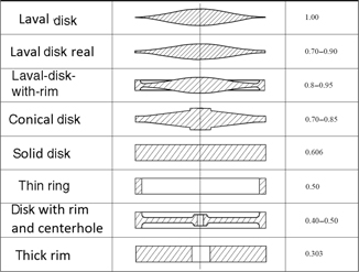
with shape factor
Shape factor K of possible fylwheel shapes
Shape 2: thin ring
Thin rings, constructed out of orthotropic materials like fiber composites, show two specific properties in comparison to disk-shaped isotropic materials:
The maximum stress occurs in circumferential direction, which is in the fiber direction of the composite materials. Since carbon fibers show an enormous strength in the fiber direction, they are an optimal material to take the circumferential stress. Due to the slender ring thickness, radial stress that normally limits the flywheel performance and that would be taken mostly by the resin is negligible.

Energy density depending on radii ratio ri/ra
If CNTs can be produced in length of cm instead of mm they would be suitable for FESS and could increase energy density of a FESS up to 2,900 W h/kg since they reach a yield strength of around 30 GPa (Yu 2000). For further calculations of shape 2, a radii ratio ri/ra of 0.9 was set. That allows us to use a simple equation for calculating the limiting circumferential stress for thin rims (Feldhusen 2001):
For thin rims, with a radii ratio ri/ra of 0.9, the shape factor decreases to
Scaling of two flywheel concepts
To see how downscaling affects the energy content, the rotational velocity and the losses due to gas and motor friction, two concepts with the following dimensions relations are considered:
| Ring: | Disk: |
|
|
|
|
|
|
|
|
|
| Vacuum in both cases: 1*10−4 mbar |
|
The CFRP-ring and the Laval-disk-with-rim shapes can be seen in Figure 3 where the Laval-disk-with-rim is assumed to be a disk with the same momentum of inertia and volume to allow the use of a less complex air loss estimation. Whenever disk shape is mentioned in the following, they imply the properties of the Laval-disk-with-rim.

Schematic shape 1: ring (left), shape 2: Laval-disk-with-rim (top right) and a solid disk (bottom right) used for the simplified air loss estimation
The mass specific energy densities are shown in Table 2. They are calculated after eqs [3] and [7] and take into account the maximum feasible rotational velocity that is limited by the yield strength. Furthermore, the mass specific energy densities are independent of the absolute dimensions. As can be seen, the energy density of the isotropic material is highest at the disk shape due to the increase of the shape factor K. The orthotropic materials show higher absolute energy densities since the strain-to-density ratio is higher. Energy densities for composite materials in disk shapes are not examined. In this case, the radial stress would be the limiting factor, which would only be determined by the comparatively low stength of the resin.
Energy densities of different flywheel materials at diskand ring shape (Torayca, T1000 Data Sheet; Torayca, T300 DataSheet)
| Material | Yield strength [MPa] |
Density
|
Energy density
|
Laval-disk-with-rim
|
| CNT | 30,000 | 1,400 | 2,693 | – |
| T1000 | 3,040 | 1,500 | 254 | – |
| T300 | 1,860 | 1,500 | 156 | – |
| Resin (for comparison) | 69 | 1,151 | 7.6 | 16 |
| Titanium TiAl6V4 | 1,100 | 4,430 | 32.3 | 65.5 |
| Steel 60SiCr7 | 1,400 | 7,430 | 24.5 | 49.7 |
| Aluminum AW-7075 | 400 | 2,700 | 19.3 | 39.1 |
| Wolfram | 1,920 | 19,300 | 12.9 | 26.3 |
Figure 4 shows the maximum resulting rotational velocity

Maximum rotational speed vs. diameter for disk (left) and ring (right)
With eq. [1], the absolute energy content of the flywheel geometries is calculated for a maximum achievable rotational velocity (see Figure 5). The highest energy content can be achieved with CNTs in a ring shape. Since the volume between ring and disk shapes is equal, the CNTs also show the best energy content-to-volume ratio. Wolfram shows the second highest energy content but only in a disk shape. Steel, in a disk shape and the T1000 composite ring, shows equivalent energy contents. The least favorable materials are titanium and aluminum when it comes to energy density regarding the volume since these materials are too light to reach adequate values.

Energy content vs. diameter for disk shape (left) and ring shape (right)
Air friction
Smaller flywheels have a smaller ratio between mass (correlated to stored energy) and surface (correlated to gas friction), and hence, the gas friction which is proportional to the surface increases. The gas friction (Pgas) can be calculated (Kolk 1997) assuming molecule to housing impacts only and no molecule to molecule impacts that would cause a viscous fluid. Since a micro-FESS would run in a highly evacuated vacuum with a rest pressure of less than
When a molecule hits the spinning rotor it transfers its momentum:
at an average
molecule per time unit hits a specific rotor surface, where
is equal to the density of molecules at pressure
Thus, the transferred angular momentum of inertia due to molecule impacts is
This leads to the total gas friction losses with the rotational velocity equal to
with an area of circle given as
and the lateral area
The gas friction losses
and for a thin ring
with
M: molar mass
T: temperature
p: pressure
h: flywheel height
and demonstrates the time period for the rotor to lose half of its kinetic energy content. Flywheels of disk shapes show 1.8 times longer half-time-periods than ring shapes, due to their larger surfaces. The air friction has also high effects on materials with lower density since they spin faster. Air friction increases proportional to the fourth degree of the flywheel radius

Half-time-period in presence of air friction vs. diameter for disk shape (left) and ring shape (right)
Motor/generator types for micro-FESS
Although there are plenty of different motor/generator types used in FESS applications, only a few can be considered as feasible and efficient for micro-FESSs’. A separately excited motor/generator is unfeasible since a separate power source for the excitation would be required.
Hence, permanent magnet excited motor/generator concepts would be suitable as they do not need an external power supply and can easily be controlled with a drive unit. This motor type normally contains iron in the stator winding to lead the magnetic flux toward the permanent magnets and thus increase the efficiency. Nevertheless, it is problematic that the iron causes hysteric losses at high speeds and thereby decreases the efficiency of the micro-FESS. Studies have shown that ironless air coil stators in combination with a magnetic Halbach array can reach higher efficiencies because the assembly of the magnet concentrates the magnetic field into one direction with only two magnet poles (see Figure 7). Thus, no iron core is needed to lead the magnetic flux through the stator coil.

Magnetic flux in a Halbach array (left) and air coil motor with Halbach array scheme (right) (Merritt and Post 1994)
Air coil motors are free from hysteresis iron losses but eddy current losses occur in the copper windings. The eddy currents are mainly related to the rotational velocity, the mass of the copper winding and the diameter of the copper wire. In Merritt and Post (1994), it was shown that a two-pole Halbach array air coil motor/generator (Halbach array length: 18 cm, Halbach array inner diameter: 7 cm and Halbach array outer diameter: 10.5 cm) reaches a discharging efficiency of more than 98% for a 23 kW motor made of a 1,700 strand wire bundle with 800 μm wires. A smaller 50 W design (2.6 cm inner stator diameter, 4.5 cm outer Halbach array diameter and 6 cm length) with four poles and a rotational velocity of up to 80,000 rpm shows an efficiency of 97% and a power density of 235 W/kg (Abdi, Milimonfared, and Moghani 2010). Also a disk motor that uses air pools and a Halbach array with 5.15 kW max. power reaches 95% efficiency and a power density of 8,100 W/kg (LaunchPoint Technologies Inc., 2009). In comparison to that, micro-motors (
As demonstrated in Kratt (2010), insulated gold wires of 25 μm diameter are manufacturable for the use of stator coils and have been wound as spools with diameter of less than 1 mm. This wire could be used to build an air spool that is located inside the ring rotor with shape 2. A stator for the flat shape 1 (Laval-rotor-with-rim) is assumed to have a similar structure as tested in Yi and Lee (2007). This Korean research group developed a flat micro-motor with a sputtered gold spool as stator (Yi and Lee 2007). Their spool was made of five windings of 50 μm high and 100 μm thick gold conductor. The magnetic field was generated by an array of flat disk-shaped permanent magnets that were fixed onto the flywheel disk (shape: solid disk made out of high-strength aluminum). This motor with its four pole pairs accelerated a 63.2 g flywheel to a speed of 52,000 rpm at a voltage of 12 V and a power of 8 W. The energy stored in this micro-FESS was 337 J (93.6 mW h).
To increase the efficiency and the power density of the motor further, the magnets should to be magnetized in a Halbach array and should be as small as possible. For very high frequencies, as necessary for composite materials in ring shapes, also hysteresis and eddy current losses in the magnets start playing a significant role concerning the losses. The smaller the magnets are, the lesser are the losses. Tarrant (1993) patented a method to implement magnetic material particles into the composite material and magnetize the field in a Halbach form. Thus rotor losses are negligible, and the problem of small-scaled magnets is solved. Also the magnet powder is part of the rotor and increases the momentum of inertia without having a negative effect on the composite yield strength. Hence for the motor loss calculation, only the eddy current losses that occur in the air spool are simulated.
Motor losses
An estimation of the motor losses
A gold wire was chosen as the conductor. A Halbach array with
Due to the aluminum construction of the rotor used in the study of Yi and Lee (2007), the maximum rotational velocity for an aluminum rotor was set as 1. To keep the voltage constant, the number of windings of the coils reduces with increasing rotational velocities. Hence, flywheels with higher rotational speeds need less gold mass to operate, due to the lesser number of windings. This is why the correction factor
The following parameters were set based on the design proposed in Yoo (2008 in COEX):
With
Correction factor
| Wolfram: | 1.22 |
| Aluminum: | 1 |
| Stahl: | 0.887 |
| Titan: | 0.77 |
| T300: | 0.54 |
| T1000: | 0.42 |
| CNT: | 0.13 |
As can be seen in Figure 8, the half-time-period due to eddy current losses

Half-time-period in presence of eddy current losses vs. diameter for disk shape (left) and ring shape (right)
Bearings
Depending on the size, the speed and the field of operation of the micro-FESS, different bearing types can be considered. Active magnetic bearings combined with permanent magnets can support a flywheel rotor in a moving environment with shocks and vibrations, as demonstrated in Yi and Lee (2007). This bearing type does not cause any friction but needs an external power supply and a controller unit to operate. This would be problematic with wireless sensor actor networks.
Passive bearings, such as electro-dynamic bearings, can also be used, as introduced in Sandtner and Bleuler (2004), to avoid an external controller and power unit. These magnetic bearings, using magnets rotating between copper wire coils, generate eddy currents at a certain rotational velocity. Thus, a reactive magnetic force lifts and stabilizes the flywheel without any additional controlling device. Losses are only generated when the rotor is displaced, in case of external shocks or vibrations. In combination with permanent magnets, an efficient, long-living and high-speed micro-FESS could be installed in applications with few vibrations and shocks. An illustration where a 1.3 kg rotor levitates at frequencies from 4,800 rpm onward, with 0.8 W lifting power, is given in Sandtner and Bleuler (2004). Since the electro-dynamic bearing starts working at a certain speed, touchdown bearings that only operate on low speeds, like ceramic roller bearings or jewel bearings, can be operationalized. For speeds up to 500,000 rpm, miniature ceramic roller bearings can be applied to support the rotor in environments with vibration and shocks.
Due to the variety of bearings and the different environment influences on the bearing efficiency, no bearing loss calculation was estimated. However, it can be said that roller bearings would be efficient for low-speed micro-FESS with high-density materials since friction increases linearly in relation to the speed, given by
Conclusions
Two types of flywheel shapes for micro-FESSs have been simulated keeping in mind the energy density, material selection, energy content, air friction and motor losses of a brushless air coil motor/generator with thin Litz wires. It was shown that isotropic materials like metals are suitable for flat disk, Laval shape with outer rim. Due to a high density, wolfram shows the best results when it comes to minimal standby-losses and high energy content-to-volume ratio. Among the examined metals, titanium shows the best mass related energy density ratio. CFRPs reach high weight specific energy densities since an optimal ring design can be selected. Energy densities 2–3 times higher than titanium can be achieved with standard carbon fibers like T300 and T1000.
Using thin wound or sputtered gold wires as motor coils reduces eddy current losses to a tolerable amount. Studies have shown that even small motors that use Halbach arrays and air spools reach efficiencies of more than 90%. This allows the use of highly efficient, permanent magnet excited motors with very low standby-losses.
Outlook
If techniques are developed to produce CNTs in a cost efficient manner and in larger filaments, they will increase energy densities by a factor of 10 compared to current CFRP FESSs. High life expectations and fast charge and discharge times make FESSs particularly interesting for energy storage devices in the future, like in cases of power backup, fast acting energy harvesting applications and mobile applications for wireless sensor actor networks and overcome their relatively expensive manufacturing.
References
Abdi, B. , J.Milimonfared, and J. S.Moghani. 2010. “Simplified Design of Slotless Halbach Machine for Micro-Satellite Electro-Mechanical Batteries.” Power Electronics, Machines and Drives (PEMD 2010) 5th International Conference, April 19–21, 1–5.Search in Google Scholar
Bleuler, H. , and J.Sandtner. 2005. Passive Magnetic Bearing for Flywheels. Berlin: Springer, Solid mechanics and its applications.Search in Google Scholar
Faulhaber. 2013. “DC-Micromotor Series 0816...SR.”Search in Google Scholar
Feldhusen, K.-H. G . 2001. “DUBBEL-Taschenbuch für den Maschinenbau.”Search in Google Scholar
Ghoniem, A. F . 2011. “Needs, Resources and Climate Change: Clean and Efficient Conversion Technologies.” Progress in Energy and Combustion Science37:15–51.Search in Google Scholar
Hu, Y.-S . 2007. Patent No. WO/2007/137794. München.Search in Google Scholar
Kolk, M . 1997. Ein Schwungrad-Energiespeicher Mit Permanentmagnetischer Lagerung. Jülich: Forschungszentrum Jülich.Search in Google Scholar
Kratt, K . 2010. Microcoils Manufactured with a Wire Bonder. Freiburg: Albert-Ludwigs-Universität Freiburg.Search in Google Scholar
LaunchPoint Technologies Inc. 2009. LaunchPoint Technologies Inc. (LAUNCHPOINT) Retrieved from http://www.launchpnt.com/portfolio/transportation/halbach-electric-motor/Search in Google Scholar
Merritt, B. T. , and R. F.Post. 1994. “Halbach Array Motor/Generators – A Novel Generalized Electric Machine.” Department of Energy by Lawrence Livermore National Laboratory, USA.Search in Google Scholar
Sandtner, J. , and H.Bleuler. 2004. “Electrodynamic Passive Magnetic Bearing with Planar Halbach Arrays.” Ninth International Symposium on Magnetic Bearings, August 3–6.Search in Google Scholar
Tarrant, C. D . 1993. Patent No. WO1994006193 A1. GB.Search in Google Scholar
Torayca. n.d. T1000 Data Sheet.Search in Google Scholar
Torayca. n.d. T300 Data Sheet.Search in Google Scholar
Wrede, C . 1998. Schwungmassen-Energiespeicher Mit Integrierten Funktionselementen. Braunschweig: RTWH Aachen.Search in Google Scholar
Yi, J. , and Lee, K. W. 2007. “Micro Flywheel Energy Storage System with Axial Flux Machine.” IEEE, September 4–7, 1–6.Search in Google Scholar
Yoo, S. Y. , and H. C.Lee. 2008. “Optimal Design of Micro Flywheel Energy Storage System.” International Conference on Control, Automation and Systems, In COEX, October 14–1.Search in Google Scholar
Yu, M.-F . 2000. “Tensile Loading of Ropes of Single Wall Carbon Nanotubes and Their Mechanical Properties.” The American Physical Society84:5552–55.Search in Google Scholar
©2014 by De Gruyter
Articles in the same Issue
- Frontmatter
- III–V Multijunction Solar Cell Integration with Silicon: Present Status, Challenges and Future Outlook
- Monolithic Integration of Diluted-Nitride III–V-N Compounds on Silicon Substrates: Toward the III–V/Si Concentrated Photovoltaics
- Study of the Growth and Dislocation Blocking Mechanisms in InxGa1−xAs Buffer Layer for Growing High-Quality In0.5Ga0.5P, In0.3Ga0.7As, and In0.52Ga0.48As on Misoriented GaAs Substrate for Inverted Metamorphic Multijunction Solar Cell Application
- Organic, Flexible, Polymer Composites for High-Temperature Piezoelectric Applications
- Modeling of a Bridge-Shaped Nonlinear Piezoelectric Energy Harvester
- Enhanced Vibration Energy Harvesting Through Multilayer Textured Pb(Mg1/3Nb2/3)O3–PbZrO3–PbTiO3 Piezoelectric Ceramics
- Load-Tolerant, High-Efficiency Self-Powered Energy Harvesting Scheme Using a Nonlinear Approach
- Comparative Analysis of One-Dimensional and Two-Dimensional Cantilever Piezoelectric Energy Harvesters
- Modeling of Hybrid Piezoelectrodynamic Generators
- Opto-electrical Behavior of Pb(Zn1/3Nb2/3)O3–Pb0.97La0.03(Zr,Ti)O3 Transparent Ceramics with Varying Defect Structure
- Feasibility Study for Small Scaling Flywheel-Energy-Storage Systems in Energy Harvesting Systems
- Ca0.15Zr0.85O1.85 Thin Film for Application to MIM Capacitor on Organic Substrate
- Erratum to EHS 1 (1–2), 69–78 (2014), A High-Temperature Thermoelectric Generator Based on Oxides
- A Direct Entropic Approach to Uniform and Spatially Continuous Dynamical Models of Thermoelectric Devices