Fabrication of Zn-Ni-Mn alloy by electrodeposition and its characterization
-
Fawzi H. Assaf
 ,
Walid M. Daoush
,
Walid M. Daoush

Abstract
Electrodeposition and stripping of Zn, Mn and Ni metals and their alloys were investigated in an aqueous sulfate solution. The effect of coating processes and its impact on the substrate were evaluated by investigating the prepared alloys with X-ray diffraction analysis, scanning electron microscopy and atomic absorption spectroscopy. The electrodeposition mechanism of the Zn-Ni-Mn alloy was found to be an anomalous type. The high corrosion resistance of the Zn-Ni-Mn alloy, as well as its preferable surface appearance, has been ascertained compared with the electrodeposited Zn-Ni alloy under homogeneous conditions. It was found that Mn can be codeposited with Ni or with Ni and Zn understudied conditions where it does not deposit in its pure form. During electrodeposition of manganese alone or manganese alloys, a dark brown deposit was formed on the counter platinum electrode surface as a result of oxidation to manganese dioxide.
1 Introduction
Coating process is considered one of the most efficacious techniques for reactive metal protection. For many years, several attempts have been made to achieve this goal, and sacrificial and barrier protection were the consequential mechanisms in which they are used.
The highly needed main targets in the industry today are reducing the coating thickness and increasing corrosion resistance. One of the more important common materials used for metal protection is Zn alloys, which have better corrosion resistance than other alloys. Therefore, replacing Zn coatings with Zn alloys has been investigated by different scientists to improve its corrosion resistance (Bahrololoom et al., 2003; Müller et al., 2003; Ramanauskas et al., 2005; Azizi & Kahoul, 2016; Faid et al., 2017).
One of the most important Zn alloys is the Zn-Ni alloy. In many previous studies, it was observed that Zn-Ni alloys have greater corrosion protection among the different types of Zn alloys. In addition to its good thermal stability, the alloy improves the mechanical possessions of the metal related to pure zinc metal and its zinc alloy coverings (Müller et al., 2001; Oliveira et al., 2017).
Several techniques have been used to improve the formation and the properties of Zn-Ni coatings. Among these are current plating (Velichenko et al., 2000; Byk et al., 2008; Chandrasekar et al., 2009), pulse plating (Ramanauskas et al., 2005) and as composition modulated alloys (Ivanov & Kirilova, 2003). The presence of an η phase (a solid solution of Ni in Zn), an α phase (a solid solution of Zn in Ni), a γ phase (Ni5Zn21) and sometimes even a δ phase (Ni3Zn22) has been elucidated within electrodeposited Zn-Ni alloy (Szczygieł et al., 2010). In addition, the changing of the deposition temperature under Galvano static conditions may lead to normal and anomalous codeposition (ACD) of zinc and nickel (Qiao et al., 2013).
The superior protective properties of electrodeposited Zn-Mn alloys make them of great significance in practical applications (Eyraud et al., 1995; Wilcox & Peterson, 1996; Bozzini et al., 2002; Sylla et al., 2005a; Savall et al., 2006; Bučko et al., 2011; Sriraman et al., 2013). The ratio of Mn content within the alloy has a significant effect on its protection potency (Kimpton et al., 2017). Reducing the manganese content in the coatings leads to a remarkable improvement in the mechanical possessions under some aggressive surroundings containing activators, such as sulfate and chloride ions, which are gaining great importance in steel protection for automotive applications. In contrast, the deposition process of Mn and Zn has some drawbacks, which are revealed to the current efficiency and bath instability.
The dual protective effect of manganese is the main factor that increases the corrosion resistance of Zn-Mn alloys. Because Mn is less noble than Zn, Mn is firstly dissolved and Zn consequently is protected. Moreover, Mn is made to form very low solubility product compounds over the galvanic coating.
Regarding the aggressive environment at which the Zn-Mn alloy can be exposed. The passive layer may contain many compounds. Many references showed that oxides (MnO, MnO2, Mn5O8 and γ-Mn2O3) and basic salts (Zn4(OH)6SO4·xH2O), in addition to zinc compounds (Zn4(OH)6SO4·xH2O), exist in abundance (Boshkov, 2003; Boshkov et al., 2006; Ortiz et al., 2009; Touazi et al., 2016).
This study investigated the combined properties of the Zn-Ni and Zn-Mn binary alloys in one Zn-Ni-Mn ternary alloy. The alloy was fabricated through an electrodeposition process as an important step for developing more effective protecting coatings. The different factors that affect the electrodeposition of a Zn-Ni-Mn ternary alloy on steel substrates from an acidic sulfate bath were studied, besides introducing a comparative study of the properties of Zn-Ni and Zn-Ni-Mn alloys based on phase composition, surface morphologies and corrosion resistance.
2 Materials and methods
All solutions that were used in the experimental study have been freshly prepared from AnalaR-grade chemicals and using double-distilled water. The electrolyte bath consists of Zn-Ni-Mn in accordance with the following ion concentrations; ZnSO4 [0.10 m], NiSO4 [0.10 m], MnSO4 [0.10 m], Na2SO4 [0.20 m], H3BO3 [0.20 m] and H2SO4 [0.01 m]. The pH value of the investigated solutions was adjusted at 2.0 (±0.1) using the CyberScan pH meter Model 500 at 25.0°C (±1°C).
All experiments were reiterated twice for precision under relatively consistent measurements. To carry out a standard bath deposition, a series of experiments at different times were performed, and the relative standard deviations have been adjusted to values of 2.5%, 1.7% and 2.2% for the Zn, Ni and Mn contents in the obtained deposit, respectively. The completed experiments have been preserved so as to not stir the solution or move the cathode.
The cathode that was used in the process of electrodeposition of Zn, Ni and Mn metals and their alloys was constructed as follows: a steel rod of 0.196 cm2 area was designed for the electrochemical measurements, such as cyclic voltammetry, galvanostatic and potentiostatic measurements, as well as for anodic linear sweep voltammetry (ALSV) and linear polarization. Secondly, steel sheets of 2 cm2 area were used for energy-dispersive X-ray fluorescence (EDXRF) analysis, X-ray diffraction (XRD) analysis, chemical composition analysis and morphological properties by scanning electron microscopy (SEM).
The electrolytic cells used were cleaned at a time using a mixture of chromic/sulfuric acids and washed at an abundance of time with distilled water. The unsullied cell was then injected with 50 ml of electroplating solution at a constant temperature of 25.0°C. The cell was carefully preserved in an air thermostat to keep the temperature at 25.0°C. The reference electrode of type Ag/AgCl/Sat. KCl was used in all potential measurements.
EG&G Potentiostat/Galvanostat model 273A, which is controlled by a PC with 352 corrosion software, was used for electrodeposition and precise measuring of electrochemical corrosion of the coatings (see Table 1).
Zn, Ni and Mn quantities in the deposit; the total weight of the deposit; the percentages of Zn, Ni and Mn; the current efficiencies of the Zn, Ni, Mn, Zn-Ni, Ni-Mn and Zn-Ni-Mn deposits; the thickness and electrochemical corrosion measurements of the deposits, galvanostatically deposited at 10 mA cm−2 and 25.0°C for 10 min on a steel substrate from a bath containing (a) Zn, (b) Ni, (c) Mn, (d) Zn-Ni, (e) Ni-Mn and (f) Zn-Ni-Mn baths.
| Parameter | Deposit |
|||||
|---|---|---|---|---|---|---|
| (a) Zn only | (b) Ni only | (c) Mn only | (d) Zn-Ni alloy | (e) Ni-Mn alloy | (f) Zn-Ni-Mn alloy | |
| Zn amount in the deposit×10−4 (g) | 32.2 | 27.9 | 31.0 | |||
| Ni amount in the deposit×10−4 (g) | 14.1 | 3.70 | 18.0 | 2.90 | ||
| Mn amount in the deposit×10−4 (g) | 0.25 | 1.80 | 0.80 | |||
| Total mass of the deposit×10−4 (g) | 32.2 | 14.1 | 0.25 | 31.6 | 19.8 | 34.7 |
| Zn content (%) | 100 | 88.2 | 89.3 | |||
| Ni content (%) | 100 | 11.8 | 90.8 | 8.30 | ||
| Mn content (%) | 100 | 9.20 | 2.40 | |||
| Zn current efficiency (eZn) (%) | 79.2 | 68.7 | 76.0 | |||
| Ni current efficiency (eNi) (%) | 38.7 | 10.2 | 49.2 | 8.0 | ||
| Mn current efficiency (eMn) (%) | 0.73 | 5.30 | 2.40 | |||
| Zn-Ni alloy current efficiency (eZn-Ni) (%) | 78.9 | |||||
| Ni-Mn alloy current efficiency (eNi-Mn) (%) | 54.5 | |||||
| Zn-Ni-Mn alloy current efficiency (eZn-Ni-Mn) (%) | 86.4 | |||||
| Thickness of the deposit (μm) | 2.26 | 0.79 | 0.02 | 2.15 | 1.13 | 2.38 |
| Corrosion potential (Ecorr.) (mV) | −998 | −284 | −212 | −865 | −409 | −756 |
| Corrosion current density (icorr.) (μA cm−2) | 107 | 4.12 | 1.94 | 41.4 | 15.7 | 25.8 |
| Polarization resistance (Rp) (kΩ) | 1.05 | 20.7 | 42.8 | 3.76 | 7.05 | 5.93 |
The cyclic voltammetry experiments have been designed, and the working electrode potential was scanned linearly and reversibly from 0.0 mV (initial value) to 1300 mV (final value). The galvanostatic measurements have been done by maintaining the current density of the cathodes in the sample solutions at a constant level of 10 mA cm−2 for 10 min.
The atomic absorption spectroscopy (AAS) model ICE 3000 (Thermo Scientific, series AA spectrometer) was used to determine the chemical composition of the formed Zn-Ni-Mn deposits. The deposited alloy layer of Zn-Ni-Mn was completely dissolved in 50.0 cm3 of a 20% HCl solution followed by diluting with two-fold distilled water up to 100 cm3; the solution was then analyzed to determine the Zn, Ni and Mn contents. The current efficiencies of the cathode for pure Zn, Ni and Mn were accurately evaluated according to Faraday’s laws (Abou-Krisha, 2005). The thickness of the deposited alloy layer was estimated depending on the densities of Zn, Ni and Mn and the amount of the deposit with the same surface area (Abou-Krisha, 2005). In addition, its cross section as well as its surface morphology were investigated by SEM (JSM-5500 LV, EEM, JEOL, Japan).
The current efficiencies of the deposited alloys were calculated using the following equation for the Zn-Ni-Mn alloy as an example:
The obtained deposits were investigated by XRD with a Bruker Axs-D8 Advance X-ray diffractometer using Cu-Kα radiation. The phase compositions of the different deposited alloys have been examined. EDXRF using the QX 2000 (Link Analytical) device calibrated with Zn, Ni and Mn standards (99.998%) (Micro-Analysis Consultants Ltd, Cambridgeshire, UK) was performed to qualitatively and semiquantitatively analyze the chemical composition of the formed Zn-Ni-Mn alloys.
3 Results and discussion
3.1 Cyclic voltammograms
Electrodeposition technique was used to prepare Zn, Ni and Mn individual metals and Zn-Ni, Ni-Mn and Zn-Mn binary alloys as well as Zn-Ni-Mn ternary alloy deposited on steel rod substrates. Sulfate bath solution at 25.0°C was first considered by cyclic voltammetry to adjust the potential ranges during the various redox processes. Figure 1A (a, b) shows a voltammogram of Zn and Ni single-handedly in sulfate media. It was observed that only one reduction peak was detected for each element in the potential scan through the negative path, and each peak was linked with the reduction of both Zn(II) and Ni(II) ions. Deposition of Zn and Ni started at −1.11 V and −0.885 V, separately. Also it was observed that in all voltammograms, a cathodic peak appeared at −0.54 V, ascribed to the codeposition of sulfur released during the reduction of sulfate groups at the cathode in the presence of H2SO4, as reported in previous work (Abou-Krisha et al., 2008). When the direction of the potential scan was changed to the positive direction at −1.3 V, an anodic peak was detected at −0.873 V for Zn and at −0.146 V for Ni. Each peak corresponds to oxidation of deposited Zn and Ni, respectively.

(A and B): i – E curves for steel in (a) Zn, (b) Ni, (c) Mn, (d) Ni-Mn, (e) Zn-Mn, (f) Zn-Ni and (g) Zn-Ni-Mn baths and a scan rate of 5 mV/s at 25.0°C.
In the cyclic voltammogram of the individual Mn metal, the anodic peak that appeared at −0.113 V was ascribed to the dissolution of deposited sulfur on the cathode surface. The height of this peak is decreased in the existence of Ni and Zn in the bath. It was observed from the same voltammogram that a cathodic peak for Mn deposition cannot be detected, indicating that Mn does not deposit under these conditions.
It is noteworthy that little work has been performed to determine the electrodeposition mechanism of pure metallic manganese. This lack in earlier research is probably due to the difficulty of reviewing the electrodeposition of Mn, specifically attributable to the very low potential value of the Mn2+/Mn(0) duo in aqueous solution
Sulfur-containing additives (e.g. ammonium sulfate, ammonium thiocyanate and sulfur dioxide) are commonly added to solutions from which manganese is electrodeposited. It has been reported (Lewis et al., 1976) that the addition of such compounds to the bath leads to deposition of manganese in the brittle α phase. In addition, the use of ammonium salts as additives has been reported to increase the efficiency of Mn(II) reduction.
To obtain a cathodic peak for Mn, electronegative potential greater than −1.3 V must be applied to the cathode. Figure 2 shows a typical voltammogram for Mn that was obtained in the absence and in the presence of ammonium thiocyanate (NH4SCN) in the potential range from −0.4 V to −1.700 V. In the voltammogram recorded in the absence of NH4SCN, the cathodic current density rapidly increased when the potential was close to −1.4 V. This increase was associated with two parallel reduction reactions: the reduction of H2O (hydrogen evolution) and the reduction of Mn(II) ions. An oxidation peak was noticeably not observed through the potential scan in the positive direction. A similar behavior was reported by Sylla et al. (2003). They ascribed the lack of this peak to the instability of the manganese deposits, which simply dissolve in acidic media. It was reported in a previous study (Díaz-Arista et al., 2006) that an electrochemical quartz crystal microbalance that was used to deposit manganese under these conditions was dissolved via a non-faradaic process (i.e. mass changes that were not associated with the charge transfer processes) during a potential scan from −1.2 V to −0.7 V in the positive direction.
![Figure 2:
i – E curves for steel in Mn bath [(A) without and (B) with 0.01 m NH4SCN] and a scan rate of 5 mV/s at 25.0°C.](/document/doi/10.1515/corrrev-2018-0003/asset/graphic/j_corrrev-2018-0003_fig_011.jpg)
i – E curves for steel in Mn bath [(A) without and (B) with 0.01 m NH4SCN] and a scan rate of 5 mV/s at 25.0°C.
The addition of NH4SCN to the bath solution had a strong effect on the voltammogram of Mn. In the course of the potential scan in the cathodic direction, the increase in cathodic current density, which is associated with the reduction of H2O and Mn(II) ions, occurred at more negative potentials than in the absence of NH4SCN. Therefore, the overpotential for the reduction of Mn(II) ions and hydrogen evolution reactions increased in the presence of the additive. This may be attributed to the presence of the additive slowing down the reaction rate of Mn(II) reduction. It is noteworthy that there is an anodic peak (Ia) for Mn dissolution in the presence of NH4SCN. This result explains that the manganese phase made in the potential scan in the cathodic direction in the existence of NH4SCN was established and easily achieves electrochemical oxidation. The sulfur that remained in the form of sulfide had occluded the coating due to the reduction of SCN− ions during the electrodeposition procedure.
In the cyclic voltammogram of the Zn-Ni system (as shown in Figure 1B f), the deposition reaction started at approximately −1.075 V. Previous studies have shown that zinc reduction processes are controlled by mass transport (Díaz-Arista et al., 2005). Detection of several peaks through the electrochemical oxidation of Zn-Ni has been ascribed to the successive oxidation of different phases (Trejo et al., 2003). Accordingly, the anodic sweep as shown in the voltammogram in Figure 1B f includes four dissolution current peaks at −0.822, −0.550, −0.294 and −0.160 V. The first dissolution peak was related to the dissolution of Zn from the pure Zn phase, the second peak was related to the dissolution of Zn from the γ-Ni5Zn21 and/or δ-Ni3Zn22 phases, the third peak was ascribed to the dissolution of Ni from the γ-Ni5Zn21 and/or δ-Ni3Zn22 phases, while the fourth dissolution peak can be attributed to the dissolution of the porous Ni matrix remaining after the preferential dissolution of Zn from the Zn-enriched phases.
For the Zn-Mn system (as shown in Figure 1B e), the deposition process started at approximately −1.060 V, while an anodic peak was observed at −0.865 V. It was observed in the voltammogram that only deposition of Zn was detected, while the reduction of Mn(II) ions did not appear. Also, this voltammogram was analogous to the voltammogram of the individual Zn metal, except that the deposition potential and the anodic peak shifted to more positive values, from −1.11 V to −1.06 V and from −0.873 V to −0.865 V, respectively. This indicated that Mn did not deposit with Zn under these conditions to form the Zn-Mn alloy.
The Ni-Mn system (as shown in Figure 1B d) was more interesting because the voltammogram was more modified than the voltammogram for the individual Ni metal. The differences were attributed to the incorporation of Mn. On the negative-going potential scan, four deposition processes were observed. The first deposition peak started at −0.585 V owing to the codeposition of sulfur. The second deposition process started at −0.906 V as a result of the deposition of Ni. The third deposition process started at −1.008 V, which was ascribed to the deposition of Mn. The fourth deposition process started at −1.169 V, which was attributed to the hydrogen evolution side reaction combined with the manganese deposition reaction. By switching the direction of the potential scan toward the positive direction at −1.3 V, an anodic peak was observed at −0.132 V, which was attributed to dissolution of the deposited Ni. In the Ni-Mn system, as shown in Figure 1A and B, the dissolution peak of pure Ni (Figure 1A b) was clearly lower than the dissolution peak of Ni (Figure 1B d), which means that Ni was deposited with a higher content when alloyed with Mn, in agreement with the Ni amount in the deposit, as listed in Table 1.
Interestingly, no Mn dissolution peak was observed when the Mn(II) and Ni(II) solutions were mixed. This was attributed to the large difference between the deposition potentials of the two cations. A displacement reaction (1) can occur during deposition:
Beyond dissolution of Mn at the anodic current, Mn will also dissolve, according to reaction (2):
The above two reactions describe the quick dissolution of Mn before the anodic potential is applied, which can explain the absence of a dissolution peak for Mn in the Mn(II) and Ni(II) bath. Wu et al. (2008) reported similar results for the electrodeposition of a Mn-Co alloy from a sulfate bath. In a previous study, a similar result was reported by Sylla et al. (2003) using a KCl+H3BO3 matrix, who also ascribed the lack of a Mn dissolution peak to instability of the manganese deposits, which are easily dissolved in acidic media. However, after a detailed study using a quartz crystal microbalance and SEM and EDX, Díaz-Arista et al. (2006) proposed that the lack of a Mn dissolution peak was due to Mn oxidation to Mn(OH)2.
In the cyclic voltammogram of the Zn-Ni-Mn system (as shown in Figure 1A g), the deposition procedure started at approximately −1.115 V (peak c1), which was analogous to the Zn deposition (c), while hydrogen evolution side reaction was indicated by c2 (Figure 1A g). Thus, it seems that the deposition potential was mainly determined by Zn. In the anodic sweep, the four peaks of the anodic current −0.965, −0.835, −0.550, and −0.294 V show the differences between the Zn-Ni-Mn and Zn-Ni systems. The peak at −0.965 V was attributed to dissolution of Mn from the Mn0.27Zn0.73 phase, the peak at −0.835 V was attributed to dissolution of Zn from the pure zinc phase, the peak at −0.55 V was ascribed to dissolution of Zn from the γ-Ni5Zn21 and/or δ-Ni3Zn22 phases, and the peak at −0.294 V was correlated with dissolution of Ni from the nickel phases. The addition of Mn to the Zn-Ni system clearly resulted in the disappearance of the fourth anodic peak that was observed in the Zn-Ni system. Moreover, the height of the first peak in the Zn-Ni system at −0.822 V increased, and the peak slightly shifted to a more negative value from −0.822 V to −0.835 V. The low height of the first anodic peak in the Zn-Ni-Mn system was due to the low content of the Mn0.27Zn0.73 phase, which therefore indicated the low content of Mn in the deposited alloy.
3.2 XRD and EDXF measurements
Figure 3 exhibits the EDXRF peaks for the Zn-Ni-Mn coating electrodeposited on a steel substrate at 10 mA cm−2 for 10 min. The peaks corresponding to the iron observed in the spectrum are due to the steel substrate. Because the EDXRF electron beam depth is higher than the deposit thickness obtained. The peaks corresponding to Zn clearly had the largest intensities, indicating that Zn was the most readily deposited metal, while Mn had the lowest intensity, indicating that Mn had the lowest content in Zn-Ni-Mn. The incorporated sulfur in the deposit was observed, as discussed previously.

EDXRF patterns for the Zn-Ni-Mn alloy electrodeposited on a steel substrate of area 2 cm2 at 10 mA cm−2 and 25.0°C for 10 min from a Zn-Ni-Mn bath.
Figure 4 shows the chemical composition and the phase analysis by XRD of the obtained Zn-Ni-Mn coating. The results revealed two high-intensity peaks and seven low-intensity peaks appeared that correspond to the pure hcp-Zn phase. Also, peaks of the hcp-Mn0.27Zn0.73 phase, cubic ε-ZnMn phase and cubic γ-Ni5Zn21 and/or tetragonal δ-Ni3Zn22 phases appeared. The peaks of iron corresponded to the steel substrate, i.e. steel sheets. This probably appeared because the X-ray electron beam penetrated the thinner deposited layer of the Zn-Ni-Mn alloy. Several intensive peaks in the XRD pattern showed the highly crystalline structure of the obtained Zn-Ni-Mn coatings. It is important to note that the peaks of the different phases observed in our study for the Zn-Ni-Mn alloy are very close, and some peaks were superimposed on one each other. The diffraction lines of the Mn0.27Zn0.73 and ε-ZnMn phases are very close to each other; therefore, the Mn0.27Zn0.73 phase or the ε-ZnMn phase may be present.

XRD patterns for the Zn-Ni-Mn alloy electrodeposited on a steel substrate of area 2 cm2 at 10 mA cm−2 and 25.0°C for 10 min from a Zn-Ni-Mn bath.
3.3 Galvanostatic technique
The potential-time dependence curves for the deposition of Zn, Ni and Mn single-handedly, and Zn-Ni, Ni-Mn and Zn-Ni-Mn alloys on steel rods substrate at 10 mA cm−2 for 10 min are shown in Figure 5. In the case of pure Ni, the deposition obviously required low overpotential to produce the first nucleus, and the deposit rate increased at lower cathodic potentials, whereas the deposition of pure Zn occurred with higher nucleation overpotential, and the deposit rate increased at higher cathodic potentials. However, the deposition of Mn required more electronegative potential than Zn or Ni to generate the first nucleus, and the rate of deposit increased at the highest electronegative potentials. The Zn-Ni, Ni-Mn and Zn-Ni-Mn alloys were codeposited at moderate overpotential values positioned between the Ni overpotential and the Zn or Mn overpotentials. The deposition potential of the Zn-Ni system was closer to the deposition potential of Zn than that of Ni, indicating that the amount of Zn in the deposit was greater than that of Ni. This is because the deposition of nickel is intensely inhibited by the presence of zinc, while the deposition of zinc is encouraged by the presence of nickel (Zech et al., 1999). This means that deposition of the Zn-Ni system was an ACD.

E – t curves for steel at 10 mA cm−2 and 25.0°C for 10 min in (A) Zn, (B) Ni, (C) Mn, (D) Ni-Mn, (E) Zn-Ni and (F) Zn-Ni-Mn baths.
Additionally, the deposition potential of the Ni-Mn system was much closer to the deposition potential of Ni than that of Mn, indicating that the main deposited metal in the Ni-Mn system was Ni. This means that the codeposition of the Ni-Mn system is a normal codeposition. On the other hand, the Zn-Ni-Mn alloy was codeposited at moderate overpotentials between those of Ni-Mn and Zn-Ni, which were deposited at more anodic and more cathodic overpotentials, respectively. The galvanostatic curve of the Zn-Ni-Mn system was located in between the galvanostatic curves of Ni or Ni-Mn and that of Zn or Zn-Ni, but was very far from the galvanostatic curve of Mn. This means that the main two components of the Zn-Ni-Mn alloy were Zn and Ni, but a very small amount of Mn was also deposited in the alloy. These results, in accordance with the results obtained from the AAS and EDXRF, showed that Zn was deposited in the highest amount, while Mn was deposited in the lowest measurable amount.
3.4 Anodic linear sweep voltammograms
The various phases and chemical forms present in the alloy will produce different current peaks in ALSV (Despić et al., 1988). Therefore, the peak structure obtained is characteristic of the components in the alloy and the phase structures of the deposit (Zećević et al., 1998).
The phase structures were investigated in a Na2SO4 solution containing complex forming ions, where Zn-Ni-Mn alloys completely dissolve. Pure Zn is well known to dissolve in a Na2SO4 solution; on the other hand, zinc alloys did not dissolve without a minor quantity of a complex forming agent, such as EDTA, present, and then together Zn and its alloys will dissolve. Similar results for dissolution of Zn-Ni alloys were obtained by Bajat et al. (2002).
Figure 6 shows the ALSV attained for individual Zn and Ni metals, and for Zn-Ni, Ni-Mn and Zn-Ni-Mn alloys through the dissolution of the deposits acquired galvanostatically at 10 mA cm−2 for 10 min at a scan rate of 5 mV s−1. It was observed from the results that both pure Zn and pure Ni had only a single anodic dissolution peak at −0.708 V and −0.089 V, respectively. Moreover, the dissolution peak of Zn was very high, but the Ni dissolution peak was very low, indicating that pure Zn was deposited with higher content. Pure Ni was deposited with lower content, which may be due to the surface effect. It is very important to note that pure Ni was deposited with lower content when deposited alone and with higher content when deposited alloyed with Mn. For the Zn-Ni alloy, there were three anodic dissolution peaks at −0.743 V, −0.394 V and −0.166 V. The first peak was attributed to dissolution of Zn from the pure zinc phase, the second peak was ascribed to dissolution of zinc from the γ-Ni5Zn21 and/or δ-Ni3Zn22 phases and the third peak was attributed to dissolution of Ni from its phases.
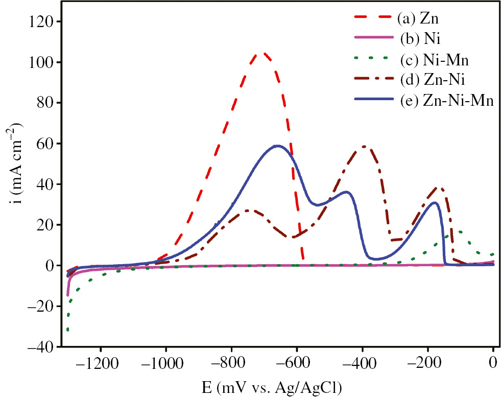
ALSVs for Zn, Ni, Ni-Mn, Zn-Ni and Zn-Ni-Mn deposits obtained galvanostatically at 10 mA cm−2 and 25.0°C for 10 min on a steel rod from (A) Zn, (B) Ni, (C) Ni-Mn, (D) Zn-Ni and (E) Zn-Ni-Mn baths, in 0.5 m Na2SO4+0.05 m EDTA at 5 mV/s and 25.0°C.
For the Zn-Ni-Mn alloy, as shown in Figure 6, there were also three anodic dissolution peaks at −0.660 V, −0.448 V and −0.177 V. The first anodic peak was attributed to the dissolution of zinc from the pure Zn phase, while the second peak was related to the dissolution of Zn from the γ-Ni5Zn21 and/or δ-Ni3Zn22 phases, which was verified by XRD as shown in Figure 4. The third anodic peak, which appeared at a more noble potential of −0.177 V, was ascribed to the dissolution of nickel from its phases. It was observed from the result that a difference between the heights of the dissolution peaks of the Zn-Ni-Mn and Zn-Ni alloys is very clear, which may be ascribed to the codeposition of manganese. Additionally, the first dissolution peak clearly shifted in the more anodic direction from −0.743 V in the Zn-Ni alloy to −0.660 V in the Zn-Ni-Mn alloy. In the second anodic peak, a clear shift toward the negative direction from −0.394 V in the Zn-Ni alloy to −0.448 V in the Zn-Ni-Mn alloy was observed. For the third dissolution peak, there was a small shift in the cathodic direction from −0.166 V in the Zn-Ni alloy to −0.177 V in the Zn-Ni-Mn alloy. It is interesting to note that the height of the anodic Zn dissolution peak when it was deposited as individual metal was higher than the peaks of the Zn-Ni or Zn-Ni-Mn alloy. This means that the amount of the pure Zn phase in these alloys was less than that in the single metal deposit.
3.5 Potentiostatic current density-time curves
Figure 7 exhibits the potentiostatic current density-time curves of pure Zn, Ni and Mn alone, and of the Ni-Mn and Zn-Ni-Mn alloys electrodeposited on steel rods at −1.300 V for 10 min. As shown from the potentiostatic curves, pure Mn required more anodic current density to form the first nucleus, and the deposit increased at very low cathodic current densities, while pure Ni needed more cathodic current density to form the first nucleus, and the deposition rate increased at very high cathodic current densities. Pure Zn needed moderate cathodic current density to create the first nucleus, and the deposit increased at moderate cathodic current densities that were between those of Mn and Ni. The potentiostatic curve of the Zn-Ni-Mn system was positioned between the potentiostatic curves of Ni and Zn, but it was very far from the potentiostatic curve of Mn, indicating that a small amount of Mn deposited in the alloy. The current density of the Zn-Ni-Mn alloy shifted to a more cathodic value as the time increased with low-frequency and magnitude fluctuations. This decrease in the cathodic current density during the first few minutes was attributed to the covering of the steel substrate by the Zn-Ni-Mn alloy, which may favor hydrogen evolution. However, the persistence of this decrease for larger times was due to a dendritic growth of the deposit that increases the active area (Sylla et al., 2005b). The fluctuations may have been caused by the formation of the hydrogen evolution side reaction via H2 bubbles (Sylla et al., 2003).
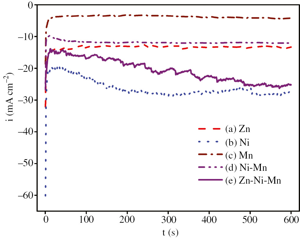
i – t curves for steel at −1300 mV and 25.0°C for 10 min in (A) Zn, (B) Ni, (C) Mn, (D) Ni-Mn, (E) Zn-Ni and (F) Zn-Ni-Mn baths.
3.6 Potentiodynamic polarization curves
The corrosion resistance of the deposits was evaluated from the potentiodynamic polarization curves as shown in Figure 8. It was obtained for pure Zn, Ni and Mn and for Zn-Ni, Ni-Mn and Zn-Ni-Mn alloys, which was electrodeposited potentiostatically at −1.300 V for 10 min from standard bath and then put in 0.05 m HCl as corrosive agent. The corrosion potential (Ecorr.), corrosion current density (icorr.) and polarization resistance (Rp) values were determined from the curves as listed in Table 1. It can observe from the results that the pure Zn had the lowest corrosion resistance when immersed in 0.05 m HCl because it had the most negative Ecorr. and the highest icorr. values, while Ni had the highest corrosion resistance because it had the lowest negative Ecorr. and the lowest icorr. values. It was also clear from the results that the Zn-Ni-Mn coating had a more positive Ecorr. value than the Zn-Ni coating, indicating that the ternary alloy showed higher corrosion resistance than the binary one. The addition of Mn to the bath containing Ni shifted the corrosion potential of Ni to a more negative value from −0.284 V to −0.409 V. It is interesting to note that the corrosion potential of Mn is not similar to the corrosion potential of Mn but represents the corrosion potential of the steel rod substrate used in the electrochemical measurements because Mn does not deposit under these conditions, and if it was deposited, the value of Ecorr. must be more negative than −0.212 V as Mn is more active than Zn and Ni.

Log i – E curves for Zn, Ni, Mn, Ni-Mn, Zn-Ni and Zn-Ni-Mn deposits obtained potentioststically at −1300 mV and 25.0°C for 10 min on a steel rode from (A) Zn, (B) Ni, (C) Mn, (D) Ni-Mn, (E) Zn-Ni and (F) Zn-Ni-Mn baths, then put in 0.05 m HCl as corrosive agent at 2 mV/s and 25.0°C.
It has been reported (Baldwin & Smith, 1996) that the potential difference of the covering and the substrate acts as a powerful force for corrosion of the sacrificial coating and defense of steel under rusting conditions. Because of the relatively large difference in the electronegativities of Zn and steel, rapid dissolution of Zn occurs under corroding conditions and reduces the coating life of pure Zn on steel, damaging the coating. This problem of rapid dissolution is mitigated by alloying Zn with Ni and Mn, which bring the Eo of the coating closer to that of the steel substrate and reduce the driving force for dissolution, enhancing corrosion resistance for a longer period and increasing the durability of the coating.
Several models have been proposed to explain the ACD of Zn alloys (Fabri-Miranda et al., 1996; Yan et al., 1996; Chen & Sun, 2001; Bahrololoom et al., 2003; Huang & Sun, 2004; Lodhi et al., 2007; Ortiz-Aparicio et al., 2007; Lichušina et al., 2008). In the display study, the competitive adsorption between Zn2+ and Ni2+ (or its monovalent intermediate) for the occupation of the active sites prompted the preferential deposition of Zn and led to ACD (Abou-Krisha et al., 2008). A few researchers (Ohba et al., 2006) have inspected the anomalous behavior and stated that it may have been due to the slower deposition kinetics of iron group metals at various concentrations of electrolytes.
3.7 The chemical composition of deposit alloys
In the absence of Mn2+, as shown in Table 1, the percentages of nickel and zinc in the Zn-Ni alloy were 11.8% and 88.2%, respectively, but after adding Mn2+ to the bath, the nickel content in the deposit decreased to 8.3%, while the zinc content slightly increased to 89.3%. This decreased nickel content may have been replaced by manganese in the deposit. The addition of manganese to the bath containing nickel and zinc first led to an increase in the alloy current efficiency from 78.9% in the absence of Mn2+ to 86.4% after codeposition of manganese (i.e. for the Zn-Ni-Mn alloy) as shown in Table 1. Secondly, an increase in the thickness of the deposit from 2.15 μm for the Zn-Ni alloy to 2.38 μm for the Zn-Ni-Mn alloy was also obtained. Thirdly, a shift toward the positive direction in the Ecorr. from −0.865 V for the Zn-Ni alloy to −0.756 V for the Zn-Ni-Mn alloy and a decrease in the icorr. from 41.4 μA/cm2 for the Zn-Ni alloy to 25.8 μA/cm2 for the Zn-Ni-Mn alloy were achieved. Finally, the Rp increased from 3.76 kΩ for the Zn-Ni alloy to 5.93 kΩ for the Zn-Ni-Mn alloy. Based on these results, the ternary Zn-Ni-Mn coating showed higher corrosion resistance properties in comparison with the Zn-Ni coating.
In Table 1, Mn codeposition was found to be normal because Mn showed the most negative electrochemical potential, and thus, it was the least present in the deposit. It is interesting that Mn can be codeposited with Ni or with Ni and Zn under the studied conditions, where it does not deposit in its pure form. Similarly, to induce codeposition, where a given element can be codeposited to form an alloy but cannot be codeposited in its pure form, interactions between the components in the deposit may shift the deposition potential of the less noble metal to more positive values (Chassaing et al., 1989).
3.8 A dark brown deposit formed on the anode (electrodeposition on the anode)
During electrodeposition of pure Mn or its alloys at the cathode from the baths containing Mn2+ ions, a dark brown deposit formed on the counter platinum electrode surface. The dark brown deposit as an anodic electrodeposition can be designated by the following equations (Ghaemi & Binder, 2002; Walanda et al., 2005).
At the cathode:
At the anode:
The reduction of H+ ions at the cathode leads to an increase in pH, while the anodic reaction produces a decline in pH.
As the above four reactions are taking place, other reactions also occur at the electrodes, with the most prominent being (Ghaemi & Binder, 2002; Walanda et al., 2005):
Because the multivalent ions represent a significant fraction of the Mn deposited at the cathode, reactions (7) and (8) cannot be neglected. Most of the Mn3+ and Mn4+ ions stay in the solution deposit at the anode as hydroxide/oxide precipitates. The overall of reactions (4) and (8) is:
The mechanism of the electrodeposition of manganese dioxide at the anode is (Ghaemi & Binder, 2002):
3.9 Surface morphology
Figure 9A and B show the SEM micrographs for the Zn-Ni and Zn-Ni-Mn alloys obtained on steel substrates at 10 mA/cm2 and 25.0°C for 10 min. The Zn-Ni binary alloy exhibits a semi-cauliflower morphology, while the Zn-Ni-Mn ternary alloy exhibits a granular morphology. The Zn-Ni alloy had a rough, non-homogeneous and non-uniform morphology, while the morphology of the Zn-Ni-Mn alloy was smoother and more homogeneous. This indicates that the addition of Mn to the Zn-Ni alloy modified the crystal growth during the electrocrystallization of the coating. Moreover, the Zn-Ni-Mn alloy possessed finer grain size than the Zn-Ni alloy, resulting in increased compactness, hardness and adherence of the coating in the presence of Mn. Thus, the addition of Mn to the Zn-Ni alloy improved the structural properties and surface morphology of the produced alloy. As seen in Figure 9A and B, the two coatings completely covered the substrate without cracks.

SEM micrographs (at magnification of 8000×) for (A) Zn-Ni (B) Zn-Ni-Mn alloys deposited on a steel substrate of area 2 cm2 at 10 mA/cm2 and 25.0°C for 10 min from (A) Zn-Ni and (B) Zn-Ni-Mn baths.
4 Conclusions
This work demonstrated the electrodeposition mechanism of individual Zn, Ni and Mn metals and Zn-Ni, Ni-Mn, Zn-Mn and Zn-Ni-Mn alloys over steel rod substrates under different experimental conditions. Comparative studies between the produced alloys were also conducted. The achieved results exposed that:
The Zn-Ni-Mn alloy exhibited ACD due to the presence of Zn and Ni.
Sulfur codeposits were formed during the electroplating of the alloys due to the reduction of the sulfate group at the cathode surface in the presence of H2SO4.
No oxidation peaks for Mn were observed during the potential scan in the positive direction due to instability of the manganese deposit, which easily dissolves in the acidic medium. However, an oxidation peak was obtained for Mn in the presence of NH4SCN.
Mn codeposited with Ni to form the Ni-Mn alloy, but did not codeposited with Zn to form the Zn-Mn alloy under ordinary conditions.
The produced Zn-Ni-Mn alloy consisted of a hexagonal pure Zn phase, a hexagonal Mn0.27Zn0.73 phase and cubic γ-Ni5Zn21 and/or tetragonal δ-Ni3Zn22 phases.
The ternary Zn-Ni-Mn alloy has a finer grain size, higher homogeneity, uniformity, adherence, hardness and compactness than the corresponding binary Zn-Ni alloy.
The ternary Zn-Ni-Mn alloy exhibited more corrosion-resistant features, thickness and current efficiency than the pure Zn and binary Zn-Ni alloys.
During electrodeposition of manganese alone or manganese alloys, a dark brown deposit was formed on the counter platinum electrode surface as a result of oxidation to manganese dioxide.
References
Abou-Krisha MM. Electrochemical studies of zinc-nickel codeposition in sulphate bath. Appl Surf Sci 2005; 252: 1035–1048.10.1016/j.apsusc.2005.01.161Search in Google Scholar
Abou-Krisha MM, Rageh HM, Matter EA. Electrochemical studies on the electrodeposited Zn–Ni–Co ternary alloy in different media. Surf Coat Technol 2008; 202: 3739–3746.10.1016/j.surfcoat.2008.01.015Search in Google Scholar
Azizi F, Kahoul A. Electrodeposition and corrosion behaviour of Zn–Co coating produced from a sulphate bath. Trans Inst Met Finish 2016; 94: 43–48.10.1080/00202967.2015.1122917Search in Google Scholar
Bahrololoom ME, Gabe DR, Wilcox GD. Development of a bath for electrodeposition of zinc-cobalt compositionally modulated alloy multilayered coatings. J Electrochem Soc 2003; 150: C144–C151.10.1149/1.1545460Search in Google Scholar
Bajat JB, Maksimović MD, Radović GR. Electrochemical deposition and characterization of zinc-nickel alloys deposited by direct and pulse current. J Serb Chem Soc 2002; 67: 625–634.10.2298/JSC0209625BSearch in Google Scholar
Baldwin KR, Smith CJE. Advances in replacements for cadmium plating in aerospace applications. Trans Inst Met Finish 1996; 74: 202–209.10.1080/00202967.1996.11871127Search in Google Scholar
Boshkov N. Zn Mn alloys electrodeposition, phase composition, corrosion behaviour and protective ability. Surf Coat Technol 2003; 172: 217–221.10.1016/S0257-8972(03)00463-8Search in Google Scholar
Boshkov N, Petrov K, Raichevsky G. Corrosion behavior and protective ability of multilayer Galvanic coatings of Zn and Zn-Mn alloys in sulfate containing medium. Surf Coat Technol 2006; 200: 5995–6001.10.1016/j.surfcoat.2005.10.002Search in Google Scholar
Bozzini B, Griskonis E, Fanigluilo A, Sulcius A. Electrodeposition of Zn–Mn alloys in the presence of thiocarbamide. Surf Coat Technol 2002; 154: 294–303.10.1016/S0257-8972(02)00010-5Search in Google Scholar
Bučko M, Rogan J, Stevanović SI, Perić-Grujić A, Bajat JB. Initial corrosion protection of Zn–Mn alloys electrodeposited from alkaline solution. Corros Sci 2011; 53: 2861–2871.10.1016/j.corsci.2011.05.039Search in Google Scholar
Byk TV, Gaevskaya TV, Tsybulskaya LS. Effect of electrodeposition conditions on the composition, microstructure and corrosion resistance of Zn-Ni alloy coatings. Surf Coat Technol 2008; 202: 5817–5823.10.1016/j.surfcoat.2008.05.058Search in Google Scholar
Chandrasekar MS, Srinivasan S, Pushpavanam M. Properties of zinc alloy electrodeposits produced from acid and alkaline electrolytes. J Solid State Electrochem 2009; 13: 781–789.10.1007/s10008-008-0607-2Search in Google Scholar
Chassaing E, Vu Quang K, Wiart R. Mechanism of nickel-molybdenum alloy electrodeposition in citrate electrolytes. J Appl Electrochem 1989; 19: 839–844.10.1007/BF01007931Search in Google Scholar
Chen PY, Sun IW. Electrodeposition of cobalt and zinc-cobalt alloys from a Lewis acidic zinc chloride-1-ethyl-3-methylimidazolium chloride molten salt. Electrochim Acta 2001; 46: 1169–1177.10.1016/S0013-4686(00)00703-9Search in Google Scholar
Despić AR, Jović VD, Zejnilović RM, Stevanović JS. Characterization of electrochemicaly formed thin layers of binary alloys by anodic linear sweep voltammetry. J Appl Electrochem 1988; 18: 511–520.10.1007/BF01022244Search in Google Scholar
Díaz-Arista P, Meas Y, Ortega R, Trejo G. Electrochemical and AFM study of Zn electrodeposition in the presence of benzylideneacetone in a chloride-based acidic bath. J Appl Electrochem 2005; 35: 217–227.10.1007/s10800-004-6304-7Search in Google Scholar
Díaz-Arista P, Antaño-López R, Meas Y, Ortega R, Chainet E, Ozil P, Trejo G. EQCM study of the electrodeposition of manganese in the presence of ammonium thiocyanate in chloride-based acidic solutions. Electrochim Acta 2006; 51: 4393–4404.10.1016/j.electacta.2005.12.019Search in Google Scholar
Eyraud M, Garnier A, Mazeron F, Crousier J. Morphology and composition of electrodeposited zinc-manganese alloys. Plat Surf Finish 1995; 82: 63–70.Search in Google Scholar
Fabri-Miranda FJ, Barcia OE, Diaz SL, Mattos OR, Wiart R. Electrodeposition of Zn-Ni alloys in sulfate electrolytes. Electrochim Acta 1996; 41: 1041–1049.10.1016/0013-4686(95)00436-XSearch in Google Scholar
Faid H, Mentar L, Khelladi MR, Azizi A. Deposition potential effect on surface properties of Zn–Ni coatings. Surf Eng 2017; 33: 529–535.10.1080/02670844.2017.1287836Search in Google Scholar
Ghaemi M, Binder L. Effects of direct and pulse current on electrodeposition of manganese dioxide. J Power Sources 2002; 111: 248–254.10.1016/S0378-7753(02)00309-9Search in Google Scholar
Huang JF, Sun IW. Nonanomalous electrodeposition of zinc-iron alloys in an acidic zinc chloride-1-ethyl-3-methylimidazolium chloride ionic liquid. J Electrochem Soc 2004; 151: C8–C14.10.1149/1.1628235Search in Google Scholar
Ivanov I, Kirilova I. Corrosion resistance of compositionally modulated multilayered Zn-Ni alloys deposited from single bath. J Appl Electrochem 2003; 33: 239–244.10.1023/A:1024179032045Search in Google Scholar
Kimpton HJ, Smith CJE, Wilcox GD. Composition and morphologies of electrodeposited zinc-nickel-manganese coatings. Trans Inst Met Finish 2017; 80: 116–119.10.1080/00202967.2002.11871447Search in Google Scholar
Lewis JE, Scaife PF, Swinkels DA. Electrolytic manganese metal from chloride electrolytes. L Study of deposition conditions. J Appl Electrochem 1976; 6: 199–209.10.1007/BF00616142Search in Google Scholar
Lichušina S, Chodosovskaja A, Sudavičious A, Juškėnas R, Bučinskienė D, Selskis A, Juzeliūnas E. Cobalt-rich Zn–Co alloys: electrochemical deposition, structure and corrosion resistance. CHEMIJA 2008; 19: 25–31.Search in Google Scholar
Lodhi ZF, Mol JMC, Hamer WJ, Terryn HA, De Wit JHW. Cathodic inhibition and anomalous electrodeposition of Zn–Co alloys. Electrochim Acta 2007; 52: 5444–5452.10.1016/j.electacta.2007.02.077Search in Google Scholar
Müller C, Sarret M, Benballa M. Some peculiarities in the codeposition of zinc–nickel alloys. Electrochim Acta 2001; 46: 2811–2817.10.1016/S0013-4686(01)00493-5Search in Google Scholar
Müller C, Sarret M, Andreu T. ZnMn alloys obtained using pulse, reverse and superimposed current modulations. Electrochim Acta 2003; 48: 2397–2404.10.1016/S0013-4686(03)00253-6Search in Google Scholar
Ohba M, Panossian Z, Camargo P. A study on zinc electrodeposition onto zinc cathode. Trans Inst Met Finish 2006; 84: 320–325.10.1179/174591906X149455Search in Google Scholar
Oliveira RP, Bertagnolli DC, da Silva L, Ferreira EA, da Paula AS, Fonseca GS. Effect of Fe and Co co-deposited separately with Zn-Ni by electrodeposition on ASTM A624 steel. Appl Surf Sci 2017; 420: 53–62.10.1016/j.apsusc.2017.05.125Search in Google Scholar
Ortiz-Aparicio JL, Meas Y, Trejo G, Ortega R, Chapman TW, Chainet E, Ozil P. Electrodeposition of zinc–cobalt alloy from a complexing alkaline glycinate bath. Electrochim Acta 2007; 52: 4742–4751.10.1016/j.electacta.2007.01.010Search in Google Scholar
Ortiz ZI, Díaz-Arista P, Meas Y, Ortega-Borges R, Trejo G. Characterization of the corrosion products of electrodeposited Zn, Zn-Co and Zn-Mn alloys coatings. Corros Sci 2009; 51: 2703–2715.10.1016/j.corsci.2009.07.002Search in Google Scholar
Qiao X, Li H, Zhao W, Li D. Effects of deposition temperature on electrodeposition of zinc–nickel alloy coatings. Electrochim Acta 2013; 89: 771–777.10.1016/j.electacta.2012.11.006Search in Google Scholar
Ramanauskas R, Gudavičiūtė L, Kaliničenko A, Juškėnas R. Pulse plating effect on microstructure and corrosion properties of Zn–Ni alloy coatings. J Solid State Electrochem 2005; 9: 900–908.10.1007/s10008-005-0049-zSearch in Google Scholar
Savall C, Rebere C, Sylla D, Gadouleau M, Refait Ph, Creus J. Morphological and structural characterisation of electrodeposited Zn–Mn alloys from acidic chloride bath. Mater Sci Eng A 2006; 430: 165–171.10.1016/j.msea.2006.05.025Search in Google Scholar
Sriraman KR, Brahimi S, Szpunar JA, Osborne JH, Yue S. Characterization of corrosion resistance of electrodeposited Zn–Ni Zn and Cd coatings. Electrochim Acta 2013; 105: 314–323.10.1016/j.electacta.2013.05.010Search in Google Scholar
Sylla D, Creus J, Savall C, Roggy O, Gadouleau M, Refait Ph. Electrodeposition of Zn–Mn alloys on steel from acidic Zn–Mn chloride solutions. Thin Solid Films 2003; 424: 171–178.10.1016/S0040-6090(02)01048-9Search in Google Scholar
Sylla D, Rebere C, Gadouleau M, Savall C, Creus J, Refait Ph. Electrodeposition of Zn–Mn alloys in acidic and alkaline baths. Influence of additives on the morphological and structural properties. J Appl Electrochem 2005a; 35: 1133–1139.10.1007/s10800-005-9001-2Search in Google Scholar
Sylla D, Savall C, Gadouleau M, Rebere C, Creus J, Refait Ph. Electrodeposition of Zn–Mn alloys on steel using an alkaline pyrophosphate-based electrolytic bath. Surf Coat Technol 2005b; 200: 2137–2145.10.1016/j.surfcoat.2004.11.020Search in Google Scholar
Szczygieł B, Laszczyńska A, Tylus W. Influence of molybdenum on properties of Zn–Ni and Zn–Co alloy coatings. Surf Coat Technol 2010; 204: 1438–1444.10.1016/j.surfcoat.2009.09.042Search in Google Scholar
Touazi S, Bučko M, Makhloufi L, Legat A, Bajat JB. The electrochemical behavior of Zn–Mn alloy coating in carbonated concrete solution. Surf Rev Lett 2016; 23: 1–10.10.1142/S0218625X1650030XSearch in Google Scholar
Trejo G, Ortega R, Meas Y, Chainet E, Ozil P. Effect of benzylideneacetone on the electrodeposition mechanism of Zn–Co alloy. J Appl Electrochem 2003; 33: 373–379.10.1023/A:1024466604939Search in Google Scholar
Velichenko AB, Portillo J, Alcobé X, Sarret M, Müller C. Nature of anode passivation in Zn–Ni electroplating baths. Electrochim Acta 2000; 46: 407–414.10.1016/S0013-4686(00)00599-5Search in Google Scholar
Walanda DK, Lawrance GA, Donne SW. Hydrothermal MnO2: synthesis, structure, morphology and discharge performance. J Power Sources 2005; 139: 325–341.10.1016/j.jpowsour.2004.06.062Search in Google Scholar
Wilcox GD, Peterson B. Zinc manganese alloy electrodeposition. Trans Inst Met Finish 1996; 74: 115–118.10.1080/00202967.1996.11871109Search in Google Scholar
Wu J, Johnsona CD, Jianga Y, Gemmena RS, Liu X. Pulse plating of Mn–Co alloys for SOFC interconnect applications. Electrochim Acta 2008; 54: 793–800.10.1016/j.electacta.2008.06.057Search in Google Scholar
Yan H, Downes J, Boden PJ, Harris SJ. A model for nanolaminated growth patterns in Zn and Zn-Co electrodeposits. J Electrochem Soc 1996; 143: 1577–1583.10.1149/1.1836682Search in Google Scholar
Zećević SK, Zotović JB, Gojković SL, Radmilović V. Electrochemically deposited thin films of amorphous Fe-P Alloy: part I. Chemical composition and phase structure characterization. J Electroanal Chem 1998; 448: 245–252.10.1016/S0022-0728(97)00417-8Search in Google Scholar
Zech N, Podlaha EJ, Landolt D. Anomalous codeposition of iron group metals: I. Experimental results. J Electrochem Soc 1999; 146: 2892–2899.10.1149/1.1392025Search in Google Scholar
©2018 Walter de Gruyter GmbH, Berlin/Boston
Articles in the same Issue
- Frontmatter
- In this issue
- Reviews
- Cathodic modification of stainless steels with ruthenium: a review of recent advances in making the cheaper option cheaper
- General properties and comparison of the corrosion inhibition efficiencies of the triazole derivatives for mild steel
- Original articles
- Fabrication of Zn-Ni-Mn alloy by electrodeposition and its characterization
- Impact of moisture on the corrosion behavior of copper and mild carbon steel in corn biodiesel
- Oil-in-water emulsion of a heterocyclic adduct as a novel inhibitor of API X52 steel corrosion in acidic solution