Laser display technologies and their applications
-
Kazuhisa Yamamoto
Kazuhisa Yamamoto is a Professor of Photon Pioneers Center, Osaka University, Japan. He received his Doctorate in Engineering from Osaka University in 1992. After pursuing his research activities in second harmonic generation and visible laser sources at Panasonic, he joined Osaka University. His current research interests focus on laser displays and laser lightings.


Abstract
Laser displays have been attractive because extremely wide color expression can be realized by choosing the wavelength of laser sources. The high efficiency and small etendue of laser sources contribute to downsizing, and a long lifetime is also another merit for users. In this paper, laser display technologies using efficient red, green, and blue lasers are reviewed. Also, applications of laser displays using these laser display technologies are introduced.
1 Introduction
A laser projection technology was proposed in 1965 [1]. The system requires red, green, and blue (RGB) lasers. It remained too costly to be used in commercially viable consumer products and too poor in performance such as very low-efficiency and large-size externals due to water-cooled Ar ion laser systems. Therefore, efficient and compact RGB lasers have been expected to realize the practical laser display [2–5].
By achievement of air-cooled RGB lasers including a red laser diode (LD), a blue LD, and a green second-harmonic-generation (SHG) laser, an advanced laser projection engine was developed in 2004 [6]. The laser projection display using the engine showed low electric consumption and wide color gamut (over 130% NTSC ratio). Figure 1 shows a color gamut of a typical laser display. Mitsubishi Electric Co. developed a commercial laser projection TV [7] in 2008 and a laser liquid crystal display (LCD) TV [8] in 2012 for home use.

Color gamut of typical laser display.
As high brightness and high power efficiency of lasers contribute to downsizing systems and improving electric efficiency, the laser projection displays are expected to bring us big displays anywhere and anytime. Therefore, microlaser projectors [9, 10] are hot topics now and have already been commercialized [11].
Table 1 shows the comparison of lasers, LEDs and UHP lumps. The laser display is attractive because of their low electric power consumption and the wide range of colors that can be realized. The high efficiency and small etendue of laser sources are advantageous for downsizing display systems [12].
Comparison of lasers, LEDs, and UHP lamps for display use.
| Laser | LED | UHP lamp | |
|---|---|---|---|
| Color gamut | 130∼140% | 100% | 70∼80% |
| (NTSC ratio) | |||
| Luminescence area | 2∼100 μm2 | 105 μm2 | 105 μm2 |
| directivity | ∼0° | 180° | 360° |
| (Divergence angle) | |||
| Polarized light use | ○ | × | × |
2 Optical configurations
Figure 2 shows two different approaches for optical configurations of laser displays. A scanning-type laser projection engine is shown in Figure 2A. The projection display system includes a laser source emitting a laser beam, and a reflecting mirror system for scanning the laser beam over an image to illuminate the image [9, 10]. The reflecting mirror system can be one or more Micro Electro Mechanical Systems (MEMS) scanning mirrors that rotate to raster scan the laser beam over the image. As the reaction of the human eyes is not quick, the image can be reconstructed on a screen.
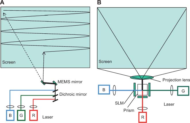
Two different approaches for optical configurations of laser displays.
(A) Scanning-type laser projection engine. (B) 2D spatial light modulator-type laser projection engine.
A 2D spatial light modulator (SLM)-type laser projection engine is shown in Figure 2B. Conventional SLMs such as the digital mirror device (DMD), liquid crystal, and liquid crystal on silicon (LCOS) are used. In this configuration, RGB lasers are used as a back light [6].
3 Technologies for laser displays
Laser displays require RGB lasers. Blue and red LDs are commercially available. On the other hand, there are no commercially available green LDs except for products with low output power. Instead, the SHG of lasers can be used to provide the green wavelengths [13–15]. In 2009, green LDs are first demonstrated as 515-nm continuous wave [16] and 531-nm pulse [17] operation by InGaN. In 2011, green LDs were mass produced by Nichia Co. (Anan-shi, Tokushima, Japan) and the improvement of those characteristics is progressing.
Speckle noise is the result of the interference of many waves on the screen due to the coherency of the laser source [18] as shown in Figure 3. Speckle is considered to be a problem in laser projection, and it is usually quantified by the speckle contrast. Speckle contrast reduction is essentially the creation of many independent speckle patterns, so that they average out on the retina. This can be achieved by wavelength diversity, angle diversity, or polarization diversity. Figure 4 shows some approaches of speckle contrast reduction. For example, by varying the incident angle of the ray to the SLM, both the reduction of speckle contrast and uniform intensity distribution are achieved. The optics constructed with a rotating lens array and a rod integrator illuminated a SLM. The rotating lens array set just in front of the rod integrator varied an angle of a laser beam and made a different wavefront in each time. The speckle contrast was suppressed by averaging these configurations. A moving screen technique is another solution. The laser TV by Mitsubishi Electric Co. [7] used such a moving screen to reduce the speckle noise.

Speckle pattern image.
Speckle pattern occurs as the result of the interference of many waves on the screen.

Representative approaches of speckle noise reduction.
(A) By laser spectrum; (B) by optics; (C) by screen.
4 Applications of laser displays
Various applications of laser displays are proposed as shown in Figure 5. Here, the laser display includes laser lighting. Table 2 shows the advantages of various laser displays. The laser display systems and applications of the laser display are introduced below.

Various applications of laser displays. It is classified into projectors, TVs, head mount displays, and laser lightings.
Advantages of various laser displays which include laser lighting.
| Low power consumption | Wide color gamut | Ultra compact | High brightness | Focus free | |
|---|---|---|---|---|---|
| Mobile projector |  | | | ||
| Data projector | ○ | ○ | | ||
| Home projector | ○ | | ○ | ||
| Pocket computer | | | | ||
| HMD | ○ | | ○ | ||
| HUD | | ○ | ○ | ○ | |
| Laser TV | | | ○ | ||
| 3D | ○ | ○ | ○ | ○ | |
| Lighting | ○ | ○ | ○ |
4.1 Laser projector
Compact and low electric power projection engines are a key technology with the potential to significantly enhance the experience of viewing visual information from mobile apparatus such as handy phones. High brightness and high efficiency of lasers contribute to downsize systems and improve electric efficiency.
Microprojection display modules based on MEMS scanning mirrors and RGB laser diodes are hot topics now. MicroVision Inc. has commercialized the microprojector with 100 cm3 size and over 15 lm [11].
Applications of the scanning-type laser projection will extend to handy computers, embedded projector modules for mobile devices, and automotive head-up displays (HUD) [11]. HUD with the laser display engine offers high contrast and brightness image to the windshield of an automotive. This system can reduce driver distraction at driving.
Embedded laser projectors by RGB lasers (including SHG green lasers) and small LCOS devices were developed. Excellent beam quality is not required for SLM-type laser projectors. A bright image over 100 lm was obtained for the 50 cm3 size of the laser projection engine [19]. Excellent projection efficiency of 20 lm/W was also demonstrated. The laser projection engine is installed in laptop PCs.
On the other hand, a high brightness laser projector (7000 lm) with ultrashort throw distance has been reported [20]. The throw ratio of 0.28 for an image of 100–150 inches was attained.
4.2 Laser TV
A laser rear projection display with a screen diagonal of over 60 inches was developed with the laser projection engine including a green SHG laser and advanced illumination optics for speckle noise reduction [21, 22]. In each light pass of RGB lasers, the rotating lens array and the rod integrator were set. SLMs of the engine were three LCD panels. Compact RGB laser units with W class light power were realized and were set in the laser projection engine. The wide color gamut, which was over 130% of NTSC ratio, brought us colorful and impressive images. As a commercial laser TV, almost the same structure was introduced [7]. By using the efficient green SHG laser and the illumination optics, the electric consumption of the display for light sources was as small as about 140 W, which is 1/3 of a conventional LCD display.
A laser LCD display [8], which has a LCD panel and a laser backlight system is also attractive because it brings us a low power consumption, a wide color gamut, and a thin light guide plates. In order to increase the efficiency of the optical system, light guide plates, which carry out polarization maintenance have been reported [23].
4.3 Head mount display
A head mount display (HMD) can create a big screen experience for small personal devices. It is demonstrated by a laser direct writing technique to the retina [24]. The head-mounted display system includes RBG laser diodes and a MEMS device. The MEMS device creates laser images from the laser light transmitted through an optical fiber. To novel virtual experiences, it delivers a new mobile scene.
4.4 Other applications
Various applications of the laser display technologies are proposed [12]. They include laser lightings and laser illuminations. Laser lighting technologies will extend the usability of lighting devices. A laser headlight and a spot lighting by a laser are examined. A laser plant factory and a fishery are promising applications of the laser lighting in the future.
Figure 6 shows the classification of applications as a function of laser power. Laser display technologies will find wide applications by an increase of the laser power.

Classification of applications as a function of laser power.
Summary
Laser displays such as laser projectors, HMDs, HUDs, and laser TVs were developed with low electric power consumption and wide color gamut by using efficient and compact RGB lasers. Table 3 shows the transition of the former and the future on research target of laser displays. Considering a further reduction of electric power consumption, the efficiency of the display part is important and should be as high as possible. By achieving more efficient RGB lasers, a laser TV with the electric consumption power of about 10 W and a microprojection engine with a size of 1 cm3 will be realized in the near future. The laser display will find wide and innovative applications instead of traditional display and lighting systems.
Transition of the former and the future on research target of laser displays.
| Research target | Efficiency (display) | |
|---|---|---|
| 1965∼ | – Large size (screen) | 0.01 lm/W |
| – High definition | ||
| 1995∼ | – Wide color gamut | 1 lm/W |
| 2005∼ | – Low electric power consumption | 20 lm/W |
| – Compact size (laser engine) | ||
| Future | – Monolithic RGB lasers | 50 lm/W |
About the author

Kazuhisa Yamamoto is a Professor of Photon Pioneers Center, Osaka University, Japan. He received his Doctorate in Engineering from Osaka University in 1992. After pursuing his research activities in second harmonic generation and visible laser sources at Panasonic, he joined Osaka University. His current research interests focus on laser displays and laser lightings.
References
[1] C. E. Baker and A. D. Rugari, Proc. SID 6th, 85 (1965).10.1080/00357529.1965.11767456Suche in Google Scholar
[2] D. E. Hargis, R. Bergstedt, A. M. Earman, P. Gullicksen, R. Hurtado, et al., Proc. SPIE 3285, 115–125 (1998).Suche in Google Scholar
[3] S. Kubota, Opt Photonics News, 13, 50–53 (2002).10.1364/OPN.13.9.000050Suche in Google Scholar
[4] E. U. Rafailov, W. Sibbett, A. Mooradian, I. G. Mclnerney, H. Karlsson, et al., Optics Lett. 28, 2091–2093 (2003).10.1364/OL.28.002091Suche in Google Scholar
[5] K. Yamamoto, Rev. Laser Eng. 36, 173–177 (2008).10.2184/lsj.36.173Suche in Google Scholar
[6] K. Kasazumi, Y. Kitaoka, K. Mizuuchi and K. Yamamoto, Jpn. J. Appl. Phys. 43, 5904–5906 (2004).10.1143/JJAP.43.5904Suche in Google Scholar
[7] T. S. Sugiura, A. Michimori, E. Toide, T. Yanagisawa, et al., Proc. SID Symposium, 39, 854–857 (2008).10.1889/1.3069805Suche in Google Scholar
[8] H. Sugiura, in ‘1st Laser Display Conference’, LDC1–2 (Yokohama, Japan, 2012).Suche in Google Scholar
[9] J.-H. Lee, Y.-K. Mun, S.-W. Do, Y.-C. Ko, D.-H. Kong, et al., Proc. SPIE 4657, 138–145 (2002).Suche in Google Scholar
[10] M. Stern, D. Yavid, F. Wood, C. Tan, C. Wittenberg, et al., in ‘Proc. 11th Microoptics Conference’, 312–315 (2005).Suche in Google Scholar
[11] J. Miller, S. Woltman and T. Byeman, ‘1st Laser Display Conference’, LDC6-2 (Yokohama, Japan, 2012).Suche in Google Scholar
[12] K. Yamamoto, in ‘The 18th International Display Workshops’, PRJ3-1 (Nagoya, Japan, 2011).Suche in Google Scholar
[13] Y. Kitaoka, K. Mizuuchi, K. Yamamoto, M. Kato, Optics Lett. 21, 1972–1974 (1996).10.1364/OL.21.001972Suche in Google Scholar PubMed
[14] K. Mizuuchi, K. Yamamoto and M. Kato, Electron. Lett. 32, 2091–2092 (1996).10.1049/el:19961366Suche in Google Scholar
[15] T. Yokoyama, K. Mizuuchi, K. Nakayama and A. Kurozuka, Jap. J. Appl. Phys. 47, 6787–6789 (2008).10.1143/JJAP.47.6787Suche in Google Scholar
[16] T. Miyoshi, S. Masui, T. Okada, T. Yanamoto, T. Kozaki, et al., Appl. Phys. Express 2, 062201 (2009).10.1143/APEX.2.062201Suche in Google Scholar
[17] Y. Enya, Y. Yoshizumi, T. Kyono, K. Akita, M. Ueno, et al., Appl. Phys. Express 2, 082101 (2009).10.1143/APEX.2.082101Suche in Google Scholar
[18] J. W. Goodman, in ‘Speckle Phenomena in Optics’, (Colorado, USA: Roberts & Co., 2007).Suche in Google Scholar
[19] T. Mizushima, K. Nakayama, K. Kusukame, T. Sugita and T. Itoh, SID Digest 40, 268–271 (2009).10.1889/1.3256760Suche in Google Scholar
[20] M. Okuda, S. Matsumoto, M. Maeda, K. Arai, K. Tsuji, et al., SID Digest 41, 972–975 (2010).10.1889/1.3500646Suche in Google Scholar
[21] T. Mizushima, H. Furuya, K. Mizuuchi, T. Yokoyama, A. Morikawa, et al., SID Digest 37, 1681–1684 (2006).10.1889/1.2433329Suche in Google Scholar
[22] T. Itoh, T. Mizushima, H. Furuya, K. Mizuuchi, A. Morikawa, et al., Jap. J. Appl. Phys. 47, 6794–6796 (2008).10.1143/JJAP.47.6794Suche in Google Scholar
[23] A. Tagaya and Y. Koike, in ‘1st Laser Display Conference’, LDC3-1 (Yokohama, Japan, 2012).Suche in Google Scholar
[24] M. Watanabe, IEICE Technical Report EID2005-27, 15 (2005).Suche in Google Scholar
©2012 by THOSS Media & De Gruyter Berlin Boston
Artikel in diesem Heft
- Masthead
- Masthead
- Editorial
- Optomechanical engineering
- Views
- Photographers are our best friends!
- Community
- News from The European Optical Society
- Conference Notes
- Conference calendar
- Topical Issue: Opto-mechanical Engineering
- Tutorial
- A practical tutorial for generating ISO 10110 drawings
- Review Articles
- A novel approach for extending autocollimator calibration from plane to spatial angles
- Lens centering of aspheres for high-quality optics
- Thermal optical path difference analysis of the telescope correct lens assembly
- Compact dual-band spectrograph
- Tutorial
- Metal-dielectric composite optical coatings: underlying physics, main models, characterization, design and application aspects
- Review Article
- Laser display technologies and their applications
- Book Review
- Introduction to Micro- and Nanooptics