Deriving the Goldschmidt-like tolerance factors for solids: a simplified polyhedral approach
-
Vasyl Sidey


Abstract
The approach to derive the Goldschmidt tolerance factor (GTF) for perovskite structures has been generalized and reformulated in terms of the geometry of regular polyhedra. The polyhedral approach was shown to be applicable for deriving the conceptual and functional GTF analogs for the non-perovskite structures containing at least two different and reasonably regular coordination polyhedra with the same or nearly the same edge lengths.
1 Introduction
The tolerance factor t [see Equation (1)] introduced by Goldschmidt in the mid-1920s 1 has been widely used in solid-state and materials sciences as a convenient criterion to evaluate the phase stability and formability of the ABX 3 perovskite structures composed of a given set of A, B and X atoms with the corresponding ionic radii r A, r B and r X. 2 , 3 Thus, it has been established that for t values lying in the approximate range 0.9–1.0, stable cubic perovskite structures are expected to exist, while the t values beyond this numeric range typically show distorted perovskite structures or non-perovskite ABX 3 phases. Furthermore, the highest stability of cubic perovskite phases is expected for the structures with the t values of ∼1, while a substantial deviation of a particular t value from unity might actually indicate the instability of a given cubic structure and its tendency to structural phase transitions.
Figure 1 schematically illustrates the unit cell of the ABX
3 cubic perovskite structure with the lattice parameter a. The shortest distances between the A-site cations and the X-site anions are equal to the half of the face diagonal of the cubic cell, whereas the distances between the B-site cations and the X-site anions are equal to half the cell edge. Hence, the A–X (d
AX) and B–X (d
BX) bond lengths in the cubic perovskite structures can be calculated from Equations (2) and (3) and it is easy to find that the structurally defined ratio (d
AX/d
BX)structural corresponding to the cubic perovskite structures is the constant equal to
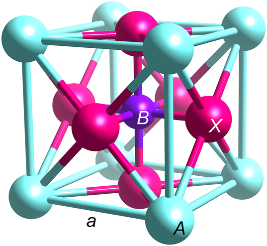
Unit cell of the cubic ABX 3 perovskite structure. The length of the cube edge is equal to the lattice parameter a.
On the other hand, the predicted ratio (d AX/d BX)predicted for a given set of the atoms A, B and X is not known a priori but can be estimated from the relevant ionic radii as [(r A + r X)/(r B + r X)].
Here it is important to note that today the bond lengths and the (d AX/d BX)predicted values can also be reliably estimated within the framework of the modern bond valence model, 4 , 5 , 6 provided that the “bond valence versus bond length” correlation curves have been accurately approximated for the relevant cation/anion pairs (i) over the full ranges of observed coordination numbers (CNs) or, at least, within the ranges corresponding to the CNs of interest, and (ii) by using the uniformly defined physical limits of the coordination shells (e.g., references [7], [8], [9], [10], [11). However, for clarity and simplicity, hereinafter the predicted bond lengths will be considered as the sums of the ionic radii, 12 as originally proposed by Goldschmidt. 1 Nevertheless, researchers should be aware of the fact that the ionic radii are not always well-defined, especially in cases where an ion may appear in different oxidation states or where the covalent character of bonding becomes predominant over purely ionic contacts.
2 Generalization of the Goldschmidt formula
Dividing the predicted ratio (d
AX/d
BX)predicted by the structurally defined ratio (d
AX/d
BX)structural =
It is easy to realize that the above generalized GTF formulation through the structurally defined and predicted ratios of the bond lengths is transferable to some other structure types and thus can be quite helpful in deriving the analogous stability and formability indicators (GTF analogs or Goldschmidt-like tolerance factors) for certain non-perovskite families of crystalline materials. Indeed, if the ratio (d′/d″)structural of the two chemically and/or structurally different interatomic distances (d′ and d″) in a given structure type is constrained to be constant (or nearly constant), then the ratio [(d′/d″)predicted/(d′/d″)structural] derived for this structure type is expected to play essentially the same informative role as the GTF for perovskites. For more convenience, dividing by the structurally defined ratio can always be replaced with multiplying by its reciprocal, [(d′/d″)structural]−1 or (d″/d′)structural. Since the (d′/d″)predicted ratio can be directly calculated from the available ionic radii 12 of the constituents (e.g., as [(r A + r X)/(r B + r X)] for perovskites), the problem of deriving the GTF analog for a given structure type is actually reduced to finding the proper mathematical expression to obtain the value of the structurally defined (d′/d″)structural ratio. In accordance with the Goldschmidt approach, the d′ and d″ values used in the above generalized ratios will be considered as the bond lengths corresponding, respectively, to the higher and lower CNs observed in a given structure type.
3 The polyhedral approach
Unfortunately, a very straightforward derivation of the GTF formula from Equations (2) and (3) [directly relating the lattice parameter and interatomic distances] masks the fact that the (d AX/d BX)structural ratio [or (d′/d″)structural in the general case] is dimensionless and that the distances in this ratio should not be necessarily connected with any structural/crystallographic parameter. In fact, the only requirement for this ratio is that the numerator and denominator must be mathematically expressed through (i.e., measured in) the same common linear parameter; so deriving the GTF analogs for other structure types in certain favorable cases can be substantially simplified by omitting the calculations based on the structural parameters such as lattice parameters and atomic coordinates. The possibility to derive the GTF and its analogs directly from the geometric properties of regular polyhedra and without considering the structural parameters is illustrated below.
Figure 2 shows the cuboctahedron [AX
12] and octahedron [BX
6] connected through the common triangular face (three common edges) in the cubic perovskite structure. The d
AX and d
BX bond lengths in these polyhedra can be respectively taken as the circumsphere radii of the cuboctahedron (R
cuboct) and octahedron (R
oct). Table 1 presents the formulae relating the edge lengths L and the circumsphere radii R for crystallochemically important regular coordination polyhedra.
13
,
14
As seen from this table, for the cuboctahedron, R
cuboct
= L
cuboct applies, whereas for the octahedron, R
oct = (L
oct/
![Figure 2:
The coordination cuboctahedron [AX
12] and octahedron [BX
6] connected through the common triangular face in the cubic perovskite structure.](/document/doi/10.1515/znb-2025-0030/asset/graphic/j_znb-2025-0030_fig_002.jpg)
The coordination cuboctahedron [AX 12] and octahedron [BX 6] connected through the common triangular face in the cubic perovskite structure.
Relationships between the circumsphere radii R and the edge lengths L for crystallochemically important regular coordination polyhedra. 13 , 14
| Polyhedron | Coordination number | Circumsphere radius R |
|---|---|---|
| Tetrahedron | 4 | (
|
| Octahedron | 6 |
L/
|
| Cube | 8 | (
|
| Cuboctahedrona | 12 | L |
-
aAnd anticuboctahedron.
As another illustrative example, the cubic AB 2 X 4 spinel structure type 15 , 16 , 17 is considered below.
The fully ordered AB
2
X
4 spinel structures are based on a nearly perfect cubic closest packing of the X anions, where one eighth of the tetrahedral voids and half of the octahedral voids are occupied by the A and B cations, respectively. The edge lengths L (i.e., the X–X interatomic distances) observed for the coordination tetrahedra [AX
4] and octahedra [BX
6] in a given spinel structure correspond to the closest packing of the X anions and, in the ideal cases, are the same. Following the Goldschmidt’s tradition to take the numerator as the bond length observed in the polyhedron with a higher coordination number, the structurally defined and predicted ratios of the lengths for spinels are written as (d
BX/d
AX)structural and (d
BX/d
AX)predicted = [(r
B + r
X)/(r
A + r
X)], respectively. From Table 1, the circumsphere radius (R
tetr) and the edge length (L
tetr) for the tetrahedron are related as R
tetr=(
Table 2 summarizes the ratios of the circumsphere radii (R′/R″) = (d′/d″)structural for pairs of regular polyhedra with the same edge lengths. If needed, the ratios for the less-common pairs of polyhedra could be derived from the extended tables of R = f(L) formulas collected in Reference 14].
Ratios (R′/R″) of the circumsphere radii for the pairs of regular coordination polyhedra with the same edge lengths. The numerators R′ and denominators R″ correspond to the radii of the polyhedra with higher and lower coordination numbers, respectively.
| Polyhedron′ | Polyhedron″ | R′/R″ |
|---|---|---|
| Cuboctahedron | Cube | 2/
|
| Cuboctahedron | Octahedron |
|
| Cuboctahedron | Tetrahedron | 4/
|
| Cube | Octahedron |
|
| Cube | Tetrahedron |
|
| Octahedron | Tetrahedron | 2/
|
4 Conclusions
Given the above facts and thoughts, the generalized GTF formula and the polyhedral approach described in this work can surely be recommended for solid state and materials scientists trying to develop the GTF analogs for the crystal structure types and families containing at least two different and reasonably regular coordination polyhedra with the same or nearly the same edge lengths.
-
Research ethics: Not applicable.
-
Informed consent: Not applicable.
-
Author contributions: The author has accepted responsibility for the entire content of this manuscript and approved its submission.
-
Use of Large Language Models, AI and Machine Learning Tools: None declared.
-
Conflict of interest: The author states no conflict of interest.
-
Research funding: None declared.
-
Data availability: Not applicable.
References
1. Goldschmidt, V. M. Naturwissenschaften 1926, 14, 477–485; https://doi.org/10.1007/bf01507527.Search in Google Scholar
2. West, A. R. Solid State Chemistry and its Applications, 2nd ed.; John Wiley & Sons: Chichester, 2014.Search in Google Scholar
3. Tilley, R. J. D. Perovskites: Structure–Property Relationships; John Wiley & Sons: Chichester, 2016.10.1002/9781118935651Search in Google Scholar
4. Brown, I. D. The Chemical Bond in Inorganic Chemistry: The Bond Valence Model, 2nd ed.; Oxford University Press: Oxford, 2016.10.1093/acprof:oso/9780198742951.001.0001Search in Google Scholar
5. Brown, I. D. Chem. Rev. 2009, 109, 6858–6919; https://doi.org/10.1021/cr900053k.Search in Google Scholar PubMed PubMed Central
6. Lufaso, M. W.; Woodward, P. M. Acta Crystallogr. 2001, B57, 725–738; https://doi.org/10.1107/S0108768101015282.Search in Google Scholar PubMed
7. Holovey, V. M.; Sidey, V. I.; Lyamayev, V. I.; Birov, M. M. J. Phys. Chem. Solids 2007, 68, 1305–1310; https://doi.org/10.1016/j.jpcs.2007.02.005.Search in Google Scholar
8. Sidey, V. I.; Milyan, P. M.; Semrad, O. O.; Solomon, A. M. J. Alloys Compd. 2008, 457, 480–484; https://doi.org/10.1016/j.jallcom.2007.03.011.Search in Google Scholar
9. Sidey, V. Acta Crystallogr. 2008, B64, 515–518; https://doi.org/10.1107/S0108768108015309.Search in Google Scholar PubMed
10. Sidey, V. Acta Crystallogr. 2010, B66, 307–314; https://doi.org/10.1107/S010876811000892X.Search in Google Scholar PubMed
11. Sidey, V. J. Phys. Chem. Solids 2022, 171, 110992; https://doi.org/10.1016/j.jpcs.2022.110992.Search in Google Scholar
12. Shannon, R. D. Acta Crystallogr. 1976, A32, 751–767; https://doi.org/10.1107/S0567739476001551.Search in Google Scholar
13. Weisstein, E. W. CRC Concise Encyclopedia of Mathematics, 2nd ed.; Chapman & Hall/CRC: Boca Raton, 2003.10.1201/9781420035223Search in Google Scholar
14. Makovicky, E.; Balić-Žunić, T. Acta Crystallogr. 1998, B54, 766–773; https://doi.org/10.1107/S0108768198003905.Search in Google Scholar
15. Hill, R. J.; Craig, J. R.; Gibbs, G. V. Phys. Chem. Miner. 1979, 4, 317–339; https://doi.org/10.1007/bf00307535.Search in Google Scholar
16. Sickafus, K. E.; Wills, J. M.; Grimes, N. W. J. Am. Ceram. Soc. 1999, 82, 3279–3292; https://doi.org/10.1111/j.1151-2916.1999.tb02241.x.Search in Google Scholar
17. Song, Z.; Liu, Q. Cryst. Growth Des. 2020, 20, 2014–2018; https://doi.org/10.1021/acs.cgd.9b01673.Search in Google Scholar
© 2025 Walter de Gruyter GmbH, Berlin/Boston
Articles in the same Issue
- Frontmatter
- In this issue
- Research Articles
- Molecular and electronic structures of molecules and ions with a linear chain of four carbon atoms: polyyne or cumulene?
- A new cobalt(II) coordination polymer: electrocatalytic hydrogen evolution reaction and electrochemical sensing of ascorbic acid in glassy carbon electrodes
- A switch from homogeneous mixed-valent to trivalent cerium in the solid solutions CeNi1–x Pd x Zn
- The metal-rich phosphide β-ZrCr6P4 with β-UCr6P4-type structure
- Palladium-coordinated Al4 butterfly clusters in the palladium-rich aluminides RE 4Pd11Al8 (RE = Y, Sm, Gd–Lu)
- Attempts to crystallize salts of thiocyameluric acid C6N7S3H3 and the crystal structure of the first hydrogen thiocyamelurate [Sr(H2O)6][HC6N7S3]
- Deriving the Goldschmidt-like tolerance factors for solids: a simplified polyhedral approach