
Systematic design of microscope objectives. Part III: miscellaneous design principles and system synthesis
-
Yueqian Zhang
Yueqian Zhang did his undergraduate study in Optical Engineering at Zhejiang University, Hangzhou, China. He received his master’s degree in Photonics from Friedrich-Schiller-Universität Jena, Germany, in 2015. Since 2016, he has been working in the Optical Design Group at the Institute of Applied Physics in Friedrich-Schiller-Universität Jena. His research interests are classical system design, microscopic application and system development.
 and
Herbert Gross
and
Herbert Gross
Herbert Gross studied Physics at the University of Stuttgart. He received his PhD on Laser Simulation in 1995. He joined Carl Zeiss in 1982, where he worked as a scientist in optical design, modeling and simulation. From 1995 to 2010, he headed the central department of optical design and simulation. Since 2012, he has been a professor at the University of Jena in the Institute of Applied Physics and holds a chair of Optical System Design. His main working areas are physical optical simulations, beam propagation, partial coherence, classical optical design, aberration theory, system development and metrology. He was the editor and main author of the book series ‘Handbook of Optical Systems.’

Abstract
In this paper, the lens modules used in the Zones 1–4 microscope objectives, which have been summarised in Part II, are utilised to create new structures. Both the modification of available systems and the synthesis of new system structures from basic building blocks are introduced. Moreover, design principles used under four special cases are introduced in this paper, including very-low-magnification Zone 5 objectives, very-high-magnification Zone 6 objectives, objectives with correction function (CORR) and objectives with diffractive optical elements, which were not systematically discussed in Part II. All the definitions and terms are based on the preceding papers.
1 Introduction
A historical review of the patented microscope objectives has been given in the connected paper Part I [1], where the systems were classified into six zones based on their etendue. The majority of the collected systems locate in Zone 1 to Zone 4, which have 443 entries holding 91.5% of the whole database (484 systems). Their system structures have been systematically analysed in the connected paper Part II [2], from the viewpoints of aberration correction, application requests and the consideration of manufacturing and technology to extract the basic building blocks as lens modules. The exceptional very-low-magnification (<4×) Zone 5 systems, as well as the very-high-magnification (>100×) Zone 6 systems, share some basic lens modules with the Zones 1–4 systems for aberration correction. However, they applied special design principles, which are only used in this zone, particularly regarding the distinctive optical power distribution. These features will be introduced in Section 2. In Part II, some special design principles of objectives with correction function (CORR) have been discussed, including optical power distribution and utilisation of air lenses. The missing general review of the feasible solutions will be given in Section 3. Furthermore, from the 1990s, a series of microscope objectives designed with diffractive optical elements (DOEs) have been patented. However, because of the stray light, the low diffraction efficiency over a wide spectrum and the critical sensitivity and robustness to fabrication tolerance, they were only used for quasi-monochromatic applications and rarely manufactured for mass production. In the recent decade, by applying the bonded-multilayer DOEs, new designs corrected for the wide spectral range can be used for mass production. The functionality of DOEs in modern microscope objectives will be introduced in Section 4. It is notable that similar to the lithographic projection lenses, aspheres are also used in some recently developed microscope objectives with extremely high etendue to improve the axial correction and control the volume of the system [3]. However, because of the limited number of collected entries, its functionality will not be discussed in this paper.
The classical development of the microscope objective was application oriented and based on the technology roadmaps of different manufacturers. Therefore, in previous literatures, a systematic synthesis approach is rarely reported [4], [5], [6], [7]. In our work, utilising the summarised lens modules and design principles, as a reversed process, a systematic synthesis approach can be achieved. For one thing, to modify the available systems for new applications, single or multiple new lens modules can be inserted or adapted to the old structure. For the other, by fixing the optical power distribution and utilising the lens modules in the front, middle and rear groups, arbitrary new structures can be synthesised. In Section 5, design examples for both considerations will be demonstrated.
2 Design principles of the Zone 5 and Zone 6 systems
2.1 Very-low-magnification Zone 5 systems
The very-low-magnification Zone 5 is defined by a magnification below 4×. According to the introduction in Sections 3.2 and 4.2 of Part I, to fulfil the requirements of telecentric object space and parfocality, nearly all the systems within this zone are designed with the ‘PNP’ optical power distribution shown in Figure 1, which consists of a positive front group close to the object, a negative middle group and a positive rear group. The middle and rear groups form a typical telephoto structure, which is different from the typical retrofocus structure used in the systems from the other zones. The additional front group plays the role of a field lens, which does not affect the telephoto structure but significantly shifts the pupil for telecentricity and corrects the field curvature.
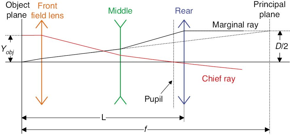
‘PNP’ optical power distribution of Zone 5 very-low-magnification microscope objectives.
Conventionally, the telephoto system can be characterised by the telephoto ratio t, which is defined in Equation (1) as the ratio between the system overall length L and the effective focal length f. In classical photographic systems, it typically lies between 0.6 and 0.9 [8]:
When it comes to the microscope objectives, the overall length L is limited by the parfocal length, which is typically standardised as 45 or 60 mm by major manufacturers. Although the optical overall length can be set slightly larger than the parfocal length, which is fixed by the mechanical shoulder, the deviation is usually within 5 mm. Assuming the microscope objectives corrected for the infinite conjugate with 200-mm tube lens, effective focal lengths of the Zones 1–4 systems are within the range between 2 and 50 mm. Therefore, the systems can realise parfocality with a symmetric structure (double Gauss) or retrofocus structure to extend working distance (WD). However, in Zone 5, the effective focal lengths of 1×, 2× and 3× objectives are tremendously enlarged to 200, 100, and 66.7 mm, which requires telephoto ratios of 0.225, 0.45, 0.675 and 0.3, 0.6, 0.9 to match the 45-mm (Leica) and 60-mm (Nikon) parfocal length, respectively. It is self-evident that designing 2× and 3× objectives is relatively simple, where the telephoto ratio matches the typical value, while the 1× objectives with very small telephoto ratio are difficult to achieve. Although the field lens is helpful to reduce the telephoto ratio, it is nearly impossible to reach the value below 0.3 with sufficient WD. It is also notable that the longer parfocal length is beneficial to realise low magnification. Therefore, Nikon patented the majority of Zone 5 systems with various relaxed structures.
Based on the telephoto structure, despite the aberration correction burden, the maximum feasible numerical aperture (NA) is limited by the standardised thread diameter DThread as Equation (2). The diameter D of the exit marginal ray bundle should be smaller than the thread diameter:
where M is the magnification and fTube is the focal length of the tube lens. Under the Royal Microscopical Society (RMS) standard thread diameter of 20.32 mm with 200-mm tube lens, the maximum NA of the 1× objective is 0.05. To extend the feasible NA and relax the optical design, manufacturers selected larger thread diameters, for instance, 25 mm used by Nikon and 27 mm used by Carl Zeiss.
The aberration behaviour of the ‘PNP’ very-low-magnification systems is field dominant, which is distinct from the aperture-dominant Zones 1–4 and Zone 6 systems. In the conventional photographic telephoto systems, to achieve quasi-telecentric object space, the aperture stop should be located behind the rear group. The external pupil introduces critical distortion and large pupil aberration. In the microscope system with epi-illumination, pupil aberration results in poor uniformity of the object illumination, which is not acceptable. Furthermore, when the telephoto ratio reduces, the lateral colour and field curvature become critical. As a consequence, the front field lens must be used to compensate the field curvature and shift the pupil for distortion correction. Thick meniscus lenses are also utilised in the front and middle groups to correct field curvature. The overall ‘PNP’ structure also fulfils Petzval’s theorem for better field curvature correction. When it comes to the lateral colour, as introduced in Section 6 of Part II, in order to correct it or compensate it, achromatic glass pairs and dense flint glasses should be selected for the lens groups with large field separation. In the Zone 5 systems, the corresponding materials can be used in both the front and rear groups.
Apart from the telephoto ratio t, the structure of the very-low-magnification systems also depends on the symmetry factor s, which is defined by the ratio between the exit axial ray bundle diameter D and the object size 2yobj. Considering the objective lens corrected for the infinite conjugate, Equation (3) gives the symmetry factor s with respect to fTube, NA and intermediate image size SF
When s=1, the general geometrical structure of the ‘PNP’ is nearly symmetric (not the ray path). Thus, both the front and rear groups can be designed rather simple. A singlet can be used as the front field lens, and cemented lens with achromatic glass selection is usually used in the rear group for both the axial chromatic aberration and the lateral colour correction. When s>1, the axial field correction is dominant. Hence, the rear group is designed with a complicated structure for spherical aberration correction, and typically, special materials are used in the rear group for lateral colour correction. When s<1, the field ray bundles are more significantly separated at the front group. Therefore, dense flint glasses and achromatic glass pairs should be used in the front group with stronger bent meniscus lenses for better pupil shift, field curvature correction and lateral colour compensation. Table 1 shows three representative ‘PNP’ very-low-magnification systems with low t low s, high t high s and high t medium s=1, respectively.
Three representative ‘PNP’ very-low-magnification Zone 5 objectives with similar intermediate image size.
| System parameters | System layout | Telephoto ratio t | Symmetry factor s |
|---|---|---|---|
| 1./0.03 SF25 Yamaguchi Nikon [9] 60-mm parfocal length | 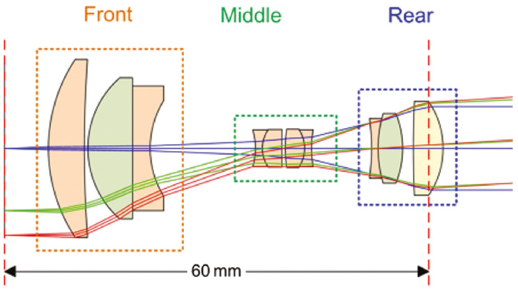 | 0.30 | 0.48 |
| 2./0.10 SF25 Otaki Nikon [10] 60-mm parfocal length | 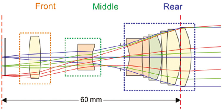 | 0.60 | 1.60 |
| 3./0.06 SF24 Klein Leica [11] 45-mm parfocal length | 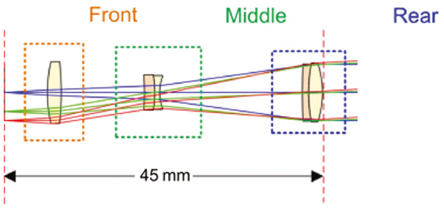 | 0.675 | 1.00 |
To further increase the object size for wide field observation, Nikon patented a 0.5× objective, which has the lowest magnification in our database. However, because of the limit of telephoto ratio (0.15 impossible), the overall length of the objective cannot fit into the parfocal length 60 mm. Therefore, the front and middle groups are designed within the parfocal length, forming an objective component attached to the turret, while the rear group is made as an auxiliary lens unit added close to the tube lens, which is schematically demonstrated in Figure 2.
![Figure 2: The 0.05×/0.025 SF25 objective [12] with the front and middle groups within the parfocal length and the rear group as an auxiliary unit.](/document/doi/10.1515/aot-2019-0014/asset/graphic/j_aot-2019-0014_fig_002.jpg)
The 0.05×/0.025 SF25 objective [12] with the front and middle groups within the parfocal length and the rear group as an auxiliary unit.
2.2 Very-high-magnification Zone 6 systems
Except for two systems designed for total internal reflection fluorescence (TIRF) applications, the other 18 collected Zone 6 objectives are designed for semiconductor inspection with long WD belonging to class 4 and class 5, which were defined in 4.3.1 of Part I (relative WD factor k=0.5–13). They are designed with nearly identical ‘PPN strong retrofocus’ structure as type (b) in table 2 of Part II. The retrofocus factors r of all the systems, which was defined as the ratio between the maximum marginal ray height in the objective (hmax) and the marginal ray height of the exit ray bundle (hexit), are smaller than 0.2, below the limit value 0.25. However, compared with the type (b) systems in Zones 1–4, with the increasing magnification, the focal length of the system reduces; thus, the axial chromatic aberration becomes more critical. Moreover, because of the requirement of long WD, to further reduce the retrofocus factor, the optical power of the negative rear group should be enlarged, while the positive front groups should have less power. The axial chromatic aberration becomes excessive in proportion to the increase in focal length of the positive subgroup [13]. Because of the enlarged diameter of the positive subgroup, the spherical aberration, field curvature and coma also become more severe under high NA [14]. Consequently, compared with typical Zones 1–4 system with the simple negative rear group, the Zone 6 systems are designed with more compound rear groups consisting of a negative front subgroup, a positive middle group and a negative rear group with strong power, which steadily narrows the ray bundle and significantly corrects the chromatic aberration. Figure 3 demonstrates the optical power distribution and two example plan-apochromate systems belonging to WD class 4 and class 5, respectively.
![Figure 3: (A) Optical power distribution of Zone 6 systems. (B) 200×/0.62 SF30 objective [15] of class 4 WD, k=13, r=0.05. (C) 250×/0.90 SF26.5 objective [14] of class 5 WD, k=0.53, r=0.13.](/document/doi/10.1515/aot-2019-0014/asset/graphic/j_aot-2019-0014_fig_003.jpg)
The lens modules utilised in the front group and middle group are the same as the Zones 1–4 systems. With the help of aplanatic meniscus shell lenses and cemented doublets and triplets, the high NA is effectively collected and the spherical aberration and axial chromatic aberration are partly corrected. The additional subgroups in the rear group are also designed with cemented lenses with achromatic glass selection and contribute to both spherical aberration and axial chromatic aberration correction. The meniscus lenses and separated ‘PNP’ structure are also helpful to correct field curvature.
3 Review of the CORR objective solutions
As introduced in Section 4.3.2 of Part I, generally there are three solutions to realise the CORR function in the microscope objectives: removable/replaceable element in front of the objective, moving component in the middle group and the utilisation of air lens effect. From the earliest solution with the removable element to the latest solution utilising air lens effect, better correction performance is achieved, and it is feasible to implement multi-adjustment including cover glass (CG) thickness, immersion liquid, temperature and imaging depth, but the mechanical structure becomes tremendously complicated. In this section, we mostly concentrate on the functionality of different solutions in CG correction.
3.1 Removable/replaceable element
The CORR objectives were originally developed for the inverted microscope. Since the thickness and material of the glass vessel, e.g. cell culture dish, are not standardised, a wide range CG correction is required. Utilising a removable/replaceable element at the front part of the objective, the change of CG can be compensated without changing the other parts of the system. Figure 4 shows a plan-fluorite 25×/0.60-long WD objective [16] designed for observation through a cell culture dish with an inverted microscope or liquid crystal display substrate for industrial inspection. Both the dish and the substrate have the shape of a plane plate, which can be considered a CG. Under case A, a plastic (nd=1.591, vd=31.00) plane plate with 1.1-mm thickness is used. The corresponding replaceable element is made of low-dispersive and low-cost NSL5 glass (nd=1.523, vd=59.89) with thickness of 1.76 mm. When another 1.2-mm NSL5 plane plate is used instead of the plastic one under case B, to compensate the induced spherical aberration and chromatic focal shift resulting from the distinctive dispersion, a 0.7-mm plane plate made of PBM28 glass (nd=1.689, vd=31.08), which has similar dispersion as the plastic material, is attached to a 0.8-mm NSL5 plane plate as a new replaceable element. Only by changing the replaceable element, the corrected configuration maintains identical axial chromatic correction and slightly changed spherical aberration without focal shift, which is shown in Figure 5. In this paper, for infinite-corrected systems, all the longitudinal aberrations are calculated under the circumstance that the tube lens is inserted behind the objective.
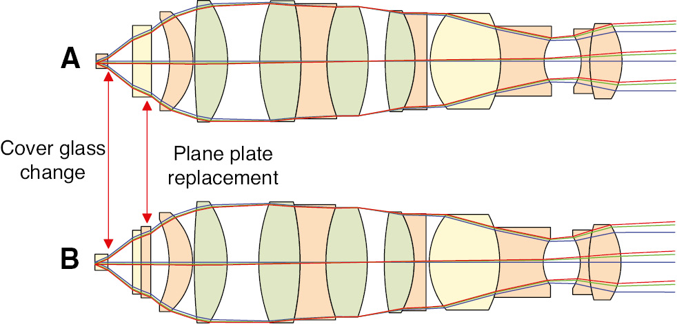
The 25×/0.6 SF10 long WD objective. (A) Used with 1.1-mm plastic plane plate. (B) Used with 1.2-mm glass plane plate.
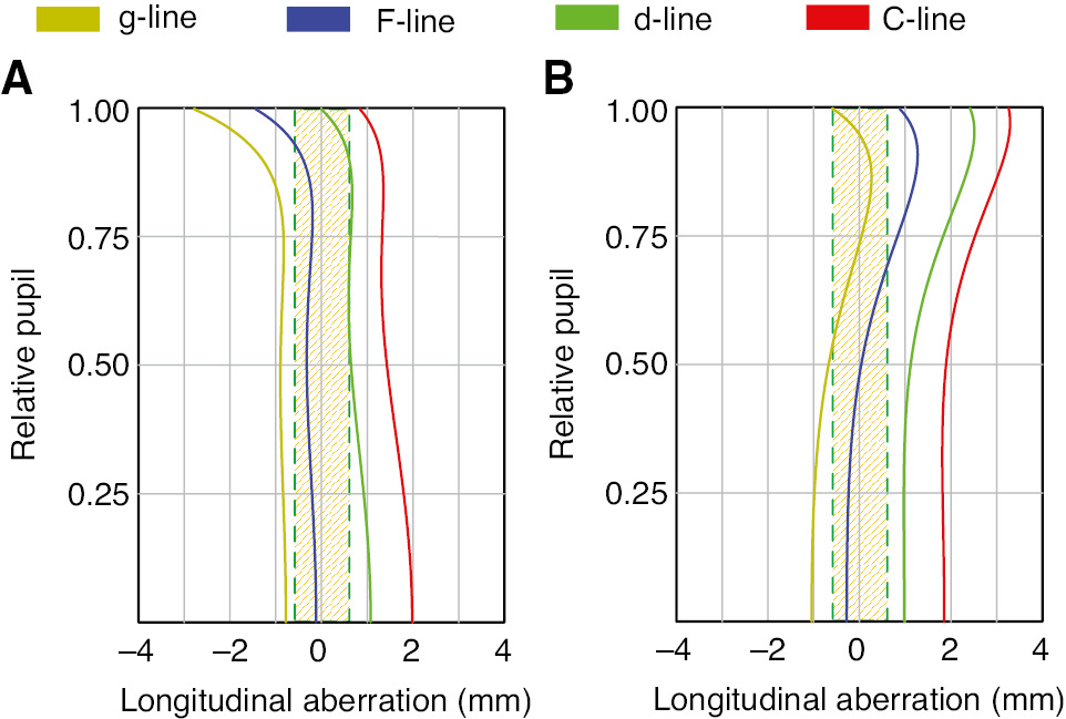
Longitudinal aberration of the 25×/0.6 objective shown in Figure 4. The shaded region indicates the DoF of the d-line. (A) Used with 1.1-mm plastic plane plate. (B) Used with 1.2-mm glass plane plate.
Although the solution with removable/replaceable element could achieve nearly consistent corrected performance, it cannot realise continuous CG adjustment. Each replaceable element is produced for a specific CG thickness and material, which is not comfortable for practical applications with arbitrary CG thickness within its fabrication tolerance. Furthermore, for high NAs (>0.7), the design of this replaceable compensating component is nearly impossible, due to the tremendous higher-order spherical aberration induced at the plane plate.
3.2 Moving components in the middle group
From the 1980s, adopting the idea of zooming photographic objectives, a setup with moving components in the middle group becomes the most popular solution. In the early patents in the 1980s and 1990s, to achieve a wide range of CG correction with short track of movement, a positive component with strong optical power was utilised. Figure 6 demonstrates three CG configurations of a plan-achromate 40×/0.55 objective [17], which could correct 0–2 mm CG thickness. Apart from the slight adjustment of the WD, 1 mm CG thickness change can be compensated by about 1-mm movement of the second cemented doublet. However, because of the great optical power (f=26.97 mm) of the moving component and the lack of the compensation group, the focus is significantly shifted. According to the longitudinal aberration of the three configurations shown in Figure 7, from case A to case C, the focal shift of the d-line is about three times the depth of focus (DoF=10 mm), which is not negligible. Because of the strong power of the moving component, from case A to case C, the working object NA is changed from 0.54 to 0.52, while the magnification is changed from 41× to 38×. These disadvantageous features change the resolution of the objective and hamper the calibration of the instrument. Furthermore, since the moving component is not free of axial chromatic aberration, its movement also hampers the chromatic correction of the objective lens. Although generally achromatic performance is maintained through the CG change, the exact axial chromatic aberration correction is significantly changed. In case A, the chromatic focal shift of the F-line and the d-line are well corrected, but it changes to the correction of the d-line and the C-line in case C. It is also notable that when the ray height increases, the strong positive lens may also introduce a large amount of higher-order spherical aberration. Therefore, this solution is also not applicable to high NA objectives.
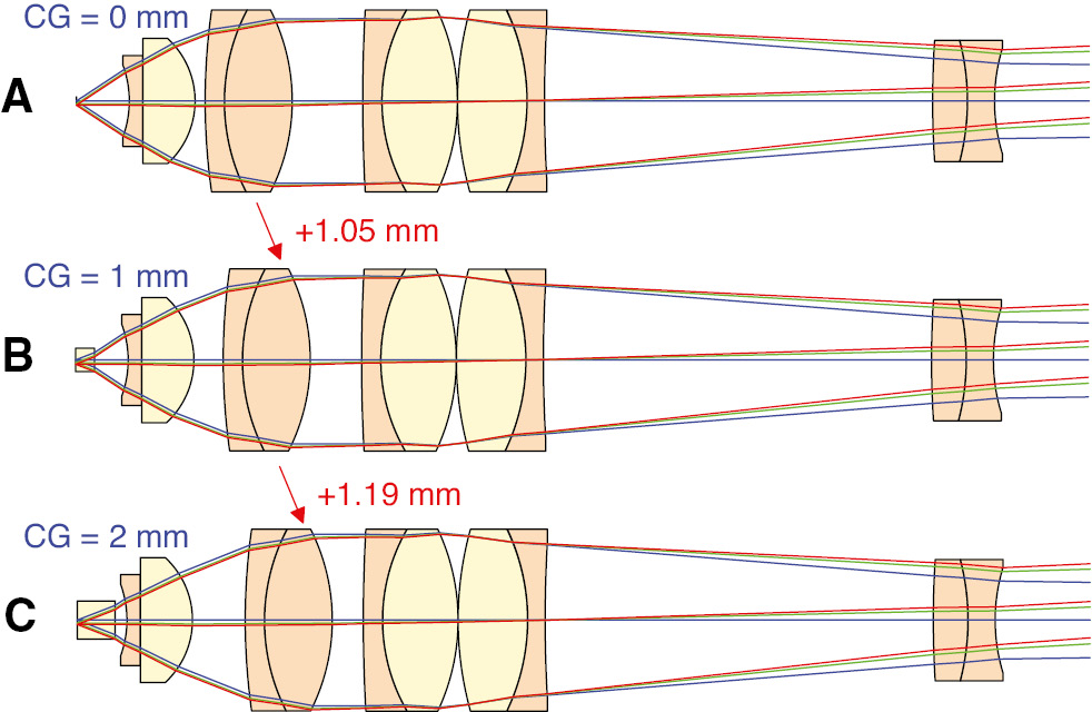
The 40×/0.55 SF18 0–2 mm CG CORR objective using a moving component with strong optical power in the middle group. Although all the components in the moving doublet and the rear doublet are coloured with light orange, they are made of different types of flint glasses. (A) Without CG. (B) CG with 1-mm thickness. (C) CG with 2-mm thickness.
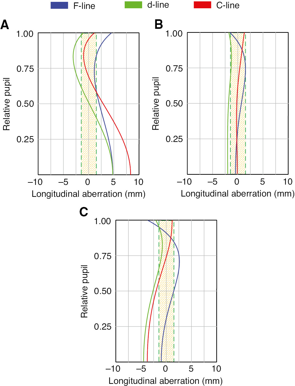
Longitudinal aberration of the 40×/0.55 objective shown in Figure 6. The shaded region indicates the DoF of the d-line. (A) Without CG. (B) CG with 1-mm thickness. (C) CG with 2-mm thickness.
To reduce the focal shift and control the chromatic change, a weak power moving component corrected for axial chromatic aberration is used in most of the modern CORR objectives. Concerning the moving track length, they can be further classified into two types. First, it is beneficial to realise wide-range CG correction by using long track movement. However, because of the limit of parfocal length, it is impossible to incorporate this feature to the objective with high NA, e.g. NA>0.9 dry objectives and immersion systems, where the lens tube is usually filled with glasses. Therefore, the CORR objectives with NA>0.9 for inverted microscopes have not been found. Second, the short track movement could realise small CG thickness deviation within the fabrication tolerance for high NA dry objectives, water immersion objectives and oil immersion TIRF objectives.
Figure 8 shows a plan-achromate 60×/0.70 objective lens [18] having 0.7–1.7 mm CG CORR function, which was designed for an inverted microscope with long moving track. The moving cemented triplet has very weak optical power (f=−534.31 mm) and utilises achromatic glass pair with anomalous dispersive material FPL53 (nd=1.439, vd=94.96) and ‘Middle Glasses’ LAL14 (nd=1.697, vd=55.53) and SK16 (nd=1.620, vd=60.29) to correct axial chromatic aberration. Because of the weak power, compared with the 40×/0.55 objective shown in Figure 6, for the large-range CG correction, the moving track should be extended. However, according to Figure 9, both the chromatic performance and focal position are better maintained.
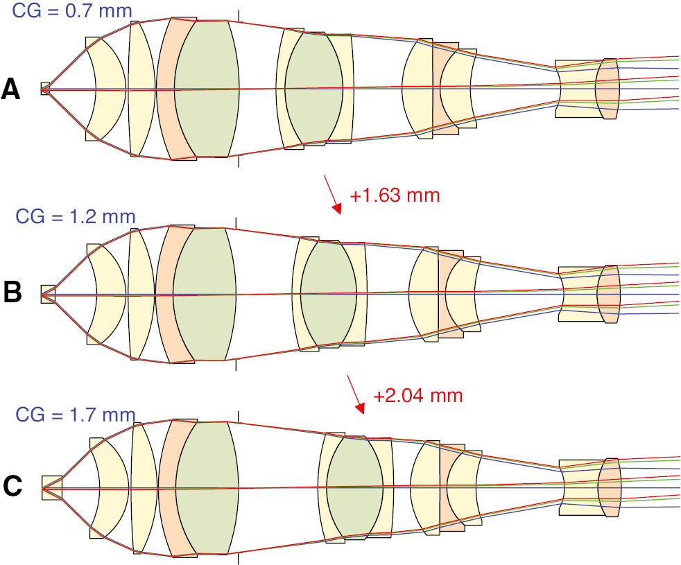
The 60×/0.70 SF18 0.7–1.7 mm CG CORR objective using weak power moving component in the middle group with long moving track. (A) CG with 0.7-mm thickness. (B) CG with 1.2-mm thickness. (C) CG with 1.7-mm thickness.
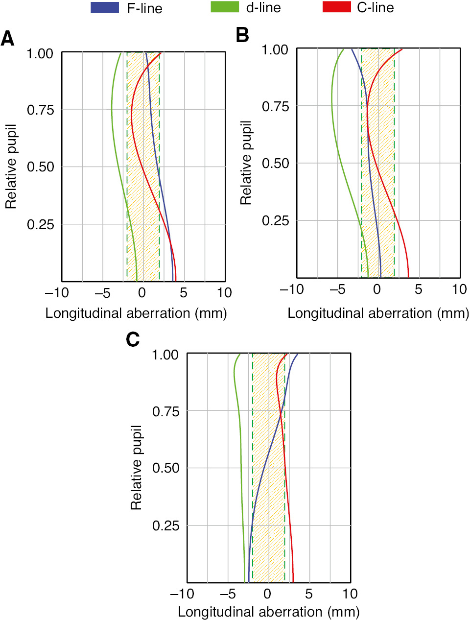
Longitudinal aberration of the 60×/0.70 objective shown in Figure 8. The shaded region indicates the DoF of the d-line. (A) CG with 0.7-mm thickness. (B) CG with 1.2-mm thickness. (C) CG with 1.7-mm thickness.
An example of the short track movement is given in Figure 10 with a plan-apochromate 40×/1.20 water immersion objective with 0.11–0.18 mm CG CORR function [19]. The correction function could be understood as the movement of the weak power cemented triplet (f=−88.50 mm), it could also be understood as the adjustment of the air lens thickness between the triplet and the Gauss-type rear group. Although the optical track length of the objective is changed during the correction, the mechanical design for the moving component can be simplified. According to Figure 11, both the chromatic performance and focal position are maintained.
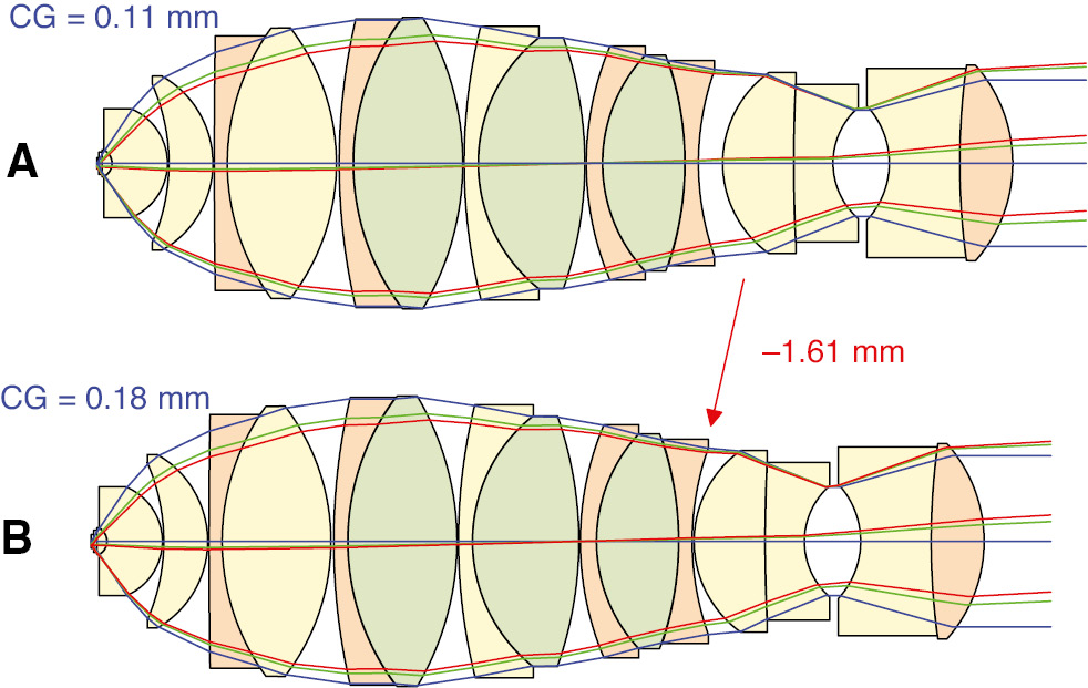
The 40×/1.20 W SF23 0.11–0.18 mm CG CORR objective using weak power moving component in the middle group with short moving track. (A) CG with 0.11-mm thickness. (B) CG with 0.18-mm thickness.
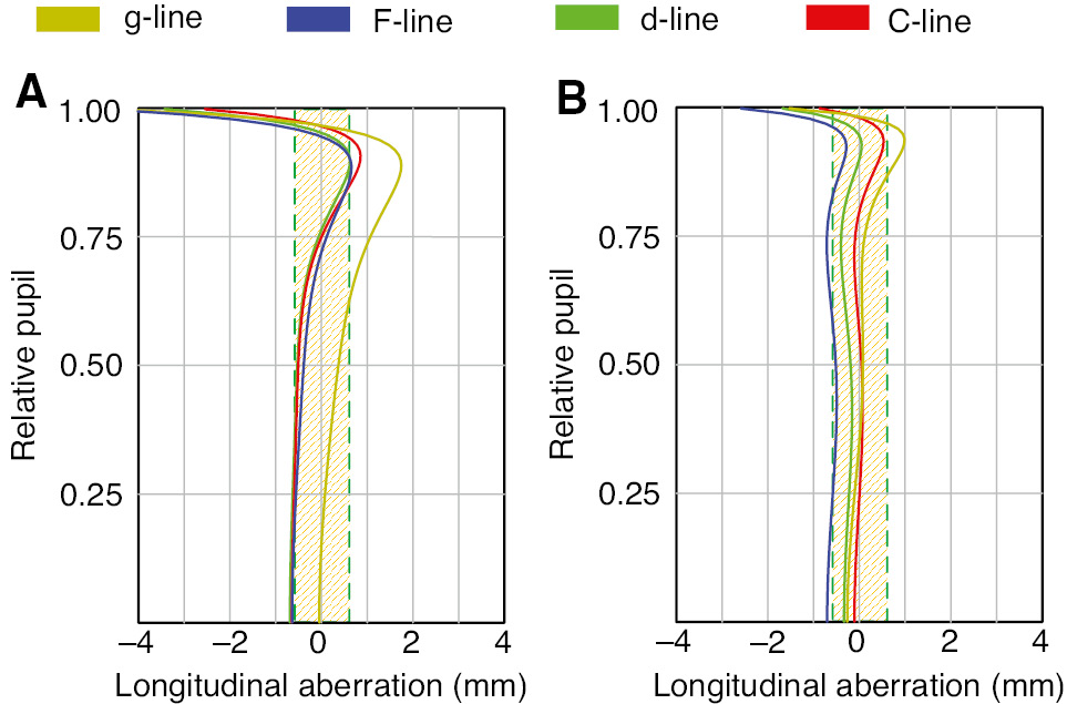
Longitudinal aberration of the 40×/1.20 objective shown in Figure 10. The shaded region indicates the DoF of the d-line. (A) CG with 0.11-mm thickness. (B) CG with 0.18-mm thickness.
3.3 Utilisation of air lens effect
To further maintain the system performance during the correction and to adjust other environmental conditions, utilisation of air lens effect is the optimal solution. In state-of-the-art systems, e.g. the 63×/1.20(1.30) multi-immersion objective [20] in Figure 12, five air lenses are adjusted to correct the CG thickness from 0.15 to 0.19 mm, the temperature from 23°C to 37°C and the immersion liquid as water and glycerine. The objective used five air lens thicknesses, where the spherical aberration is most sensitive. During the CG correction from 0.15 to 0.19 mm, the component pair E2 and E4 should be moved toward opposite directions, as well as the component pair E5 and E6. In fact, the CORR function realised by multiple air lenses can also be understood as a zooming system with mechanical compensation, while the previously discussed CORR objectives with a single moving component correspond to the zooming systems with optical compensation. According to Figure 13, owing to the mechanical compensation, the focal position is nearly fixed, while the axial chromatic aberration and spherochromatism (SPHCRM) are also kept constant during the correction. However, the mechanical design for the moving components becomes tremendously complicated.
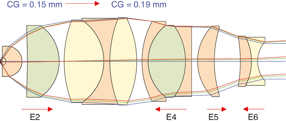
The 63×/1.20 W (1.30 G) SF20 0.15–0.19 mm CG CORR objective using five air lenses.
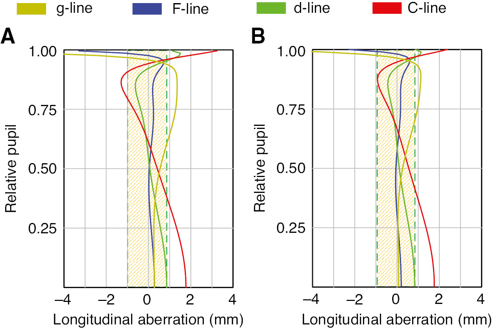
Longitudinal aberration of the 63×/1.20 objective shown in Figure 12. The shaded region indicates the DoF of the d-line. (A) CG with 0.15-mm thickness. (B) CG with 0.19-mm thickness.
Comparing the applicable system parameter, corrected performance and complexity of the objective mechanical design, the solutions to realise CORR function are summarised in Table 2.
Summary of the solutions for CORR objectives.
| No. | Solutions | NA | CG range | Focus | Chromatic correction | Mechanical complexity |
|---|---|---|---|---|---|---|
| 1 | Removable/replaceable element | Medium (<0.7) | Discontinuous | Fixed | Preserved | No change |
| 2 | Strong power moving group without chromatic correction | Medium (<0.7) | Wide | Shifted | Violated | Simple |
| 3 | Weak power moving group with chromatic correction and long moving track | Medium-high (<0.9) | Wide | Shifted within DoF | Preserved | Simple |
| 4 | Weak power moving group with chromatic correction and short moving track (air lens) | High | Narrow | Shifted within DoF | Preserved | Simple |
| 5 | Multiple air lenses | High | Narrow | Fixed | Preserved (SPHCRM) | Sophisticated |
SPHCRM indicates the CORR function of spherochromatism.
4 Objectives with DOEs
The utilisation of DOEs in microscope objectives started in the 1990s. Designed for a single wavelength, from the geometrical point of view, DOEs have a similar functionality as that of aspheres in correcting optical systems. However, according to their working principle, they have completely different spectral behaviour in comparison with refractive optical elements. As opposed to the positive Abbe number of the optical glasses and plastics, DOEs have a negative value, e.g. the d-line Abbe number
However, apart from the benefits in correcting monochromatic and chromatic aberrations, the conventional single-layer DOEs, which is shown in Figure 14A, encounter critical problems in practical applications working with wide spectral range. First, since the ideal blaze condition is only valid for one incidence angle to generate the desired diffraction order for correction, the stray light introduced by the unwanted diffraction orders and finite incidence angle is unavoidable and must be controlled by selecting an appropriate position of the DOE in the optical system. Second, since the blaze condition is only valid for one wavelength, the wide spectral range results in the drop of diffraction efficiency, which is the most critical problem. The efficiency of a blazed DOE as a function of the wavelength is given as Equation (4) in the scalar approximation, where m is the diffraction order:
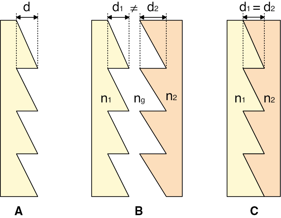
DOE structures. (A) Single-layer DOE. (B) Separated-multilayer DOE. (C) Bonded-multilayer DOE.
In a typical microscope objective corrected for visible range from the g-line to the C-line, assuming the designed wavelength at the d-line, the diffraction efficiency typically drops down to 0.6 at the g-line, which significantly hampers the contrast of the image. To improve the efficiency, separated-multilayer DOE, shown as Figure 14B, was invented in late 1990s [22], [23], [24]. By appropriately selecting the materials of the two components and calculating the different depths of the structure d, according to Equation (5), the phase φ difference for two wavelengths can be a multiple of 2π, realising achromatisation:
Utilising additional layers, the achromatisation can even be achieved for four wavelengths covering the visible spectrum. However, the fabrication of the DOE components requires at least two moulds, and the alignment is critical, resulting in high cost. Therefore, as shown as Figure 14C, another approach with bonded-multilayer DOE with identical structure depth on the two components becomes the most realistic solution for DOE mass production [25], [26]. Under this circumstance, considering the DOE used for the F-line to the C-line, if the refractive indices of the two components fulfil the condition in Equation (6) [26], [27], achromatisation is achieved. The two materials should be selected with nearly matched index and different dispersion. Owing to the small difference of refractive indices, the depth of the diffractive structure can be enlarged, which is an advantage for the manufacturing process.
The last but not least drawback of the DOE is the high requirement for fabrication accuracy, which results in high cost. The roughness, tolerance of the surface geometry and non-sharp edges result in critical stray light. Because of these drawbacks, the single-layer DOE was only utilised in a limited number of microscope objectives working quasi-monochromatically in DUV, e.g. 193 nm [28], [29]. The separated-multilayer DOE was well developed by several Japanese manufacturers but has not been reported for high mass production. When it comes to the bonded-multilayer DOE, although it was also first reported in the 1990s, the mass production was not seen before 2010, because it was difficult to select optical materials, which are suitable for accurate fabrication with low cost and fulfil the achromatisation condition simultaneously. In 2008, Nikon reported two types of resins: type A (nd=1.5569, vd=50.2) and type B (nd=1.5276, vd=34.7) [30]. The UV-curable resin type A is first dripped onto a flat substrate and then pressed by a mould, on which the relief pattern is formed. Curing the resin and dripping the type B resin onto the moulded surface, the DOE is finally achieved by using another flat substrate pressing from the other side. With this simple process, it is feasible to produce DOEs with high accuracy and relatively low cost for mass production. In the recent decade, utilising these bonded-multilayer DOEs, Nikon patented various microscope objectives with achromatic and apochromatic performance corrected for visible range.
Most of the recently reported microscope objective (18 entries out of 34 collected systems) utilised the DOEs for further extension of WD. According to Section 3 in Part II and Section 2.2 in this paper, it is known that the chromatic aberration becomes more critical with decreasing retrofocus factor. Because of the enlarged ray height in the middle group, it is also more difficult to correct the spherical aberration. Owing to the special spectral behavior and asphere-like functionality, the DOE is suitable for both corrections. To reduce the stray light introduced by finite incidence angle, the DOE should be placed in the middle group, where the aperture angles of all the fields are relatively small. Furthermore, to exclude the stray light from unwanted diffraction orders, it is better to place a strong negative group following the DOE [31]. To fulfil the first condition, because of the very weak optical power, the DOEs are usually placed at the same position as the moving component in the CORR objectives, corresponding to the type (e)-(f) power distribution shown in table 2 of Part II. The second condition is naturally realised in long WD systems with ‘PPN strong retrofocus’ power distribution.
Figure 15 shows two 50×/0.55-long WD (k=2.65) objectives with nearly identical geometry and equivalent glass selection. The system (A) only adds one bonded multi-layer DOE at the end of the middle group but reduces the chromatic focal shift as half of that in system (B) and improves the axial chromatic correction from class (b) fluorite level to class (c) apochromate level, which can be seen from the longitudinal aberrations in Figure 16.
![Figure 15: (A) 50×/0.55 LD SF25 objective with DOE [32]. (B) 50×/0.55 LD SF25 objective without DOE [33].](/document/doi/10.1515/aot-2019-0014/asset/graphic/j_aot-2019-0014_fig_015.jpg)
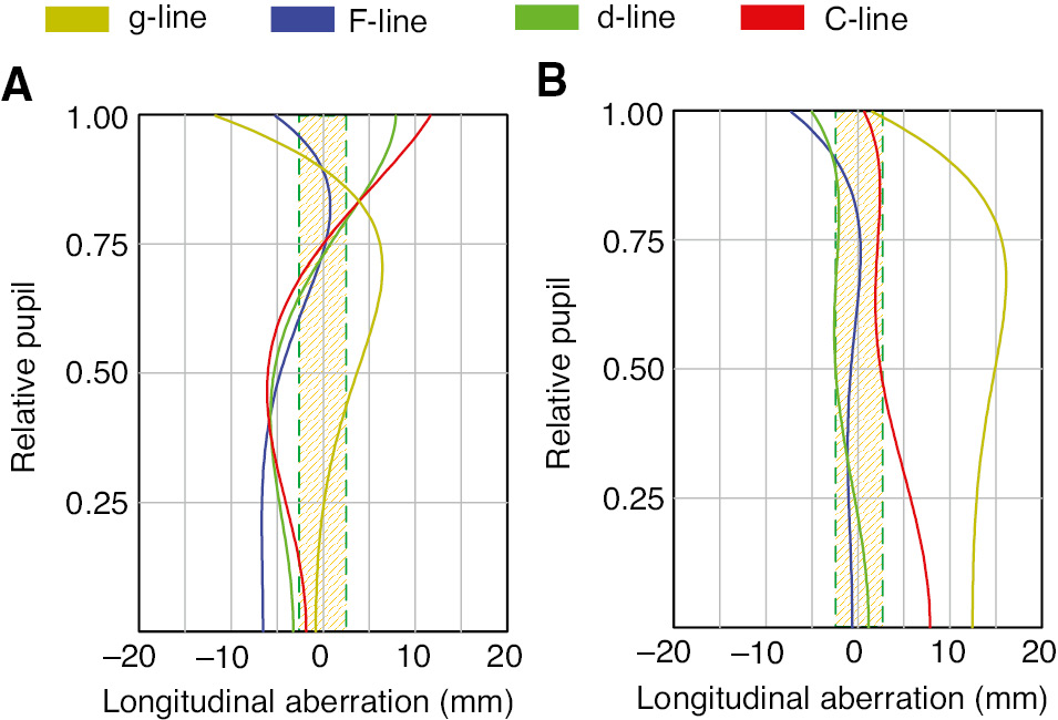
Longitudinal aberration of the 50×/0.55 objectives shown in Figure 15. The shaded region indicates the DoF of the d-line. (A) With DOE. (B) Without DOE.
Recently, the DOEs are also introduced into the systems with extremely high etendue as hybrid lenses. Similar to the functionality of asphere in lithographic projection lenses [8], the hybrid lens can significantly reduce the lens diameter and shorten the total track. Two Nikon 25×/1.10 water immersion objectives are given in Figure 17, achieving nearly identical etendue; the system with hybrid lens saves one lens in the front group and two lenses in the middle group but doubles the WD. These advantageous features benefit from the relaxed correction of spherical aberration and axial chromatic aberration owing to the 7.57% reduced marginal ray height in the middle group. Furthermore, because of the fewer number of components, the total track of the system decreases 18.46%. Therefore, the hybrid objective can fit into the standardised 60-mm parfocal length.
![Figure 17: Functionality of hybrid lens in reducing the system length and diameter. (A) 25×/1.10 W SF25 objective with hybrid lens [34]. (B) 25×/1.10 W SF22 objective without DOE [35].](/document/doi/10.1515/aot-2019-0014/asset/graphic/j_aot-2019-0014_fig_017.jpg)
5 System synthesis
Through the three connected papers, the building blocks and design principles utilised in most of the modern microscope objectives have been systematically sorted and analysed. Three major aspects of impacts determine the lens module selection, including aberration correction, application requests and the consideration of manufacturing and technology. As a reverse process, the workflow of the system synthesis is shown in Figure 18, in which the utilised lens modules also originate from the three claimed aspects.
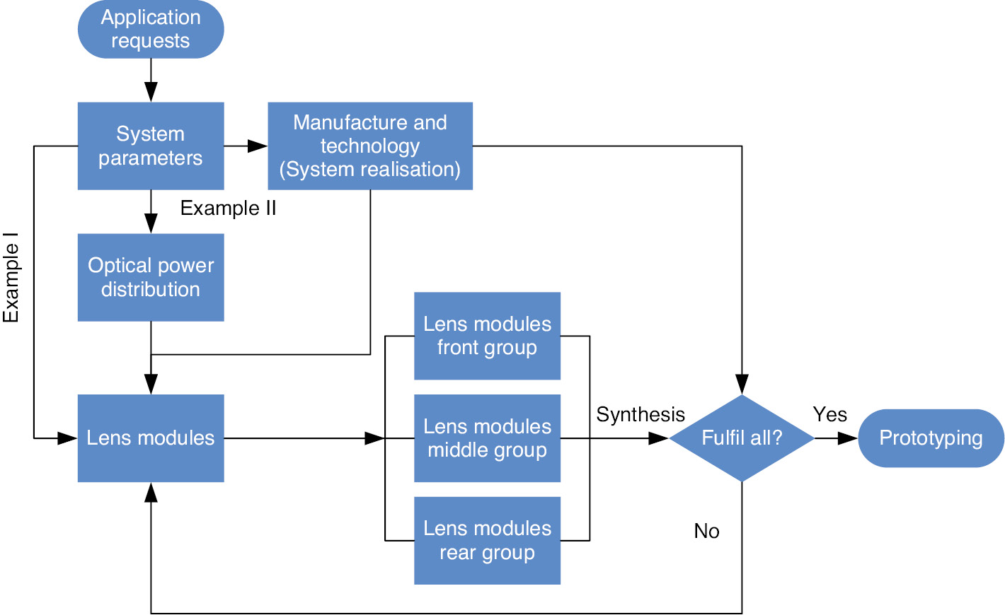
Workflow of the microscope objective synthesis.
The design of the microscope objective is mostly application oriented. Based on table 2 of Part I, the system parameters are determined with fixed correction level of chromatic aberration and field aberration. According to these parameters, several lens modules can be directly fixed, and the corresponding manufacturing and technology also set certain boundary conditions and predetermine some lens modules. As the major aspect of consideration, regarding the system parameters, the optical power distribution should be carefully selected out of table 2 of Part II. Then, synthesising the lens modules from the front, middle and rear groups, the new objective structure can be achieved and checked with the boundary conditions given by the manufacturing and technology considerations.
In this section, example I illustrates the process of system modification for a new application request. When the application is slightly changed, without disturbing the basic structure of the objective lens by keeping the optical power distribution, several lens modules belonging to front, middle and rear groups are introduced locally into the system to match the new system parameters.
Example II illustrates the process of system synthesis from the basic lens modules. The optical power distribution is first fixed, and the lens modules are inserted step by step to gradually match the required system parameters.
5.1 Modification of available system for new application
A patented 40×/0.85 SF26.5 plan-apochromate objective [36] is considered as the initial system. The 45-mm parfocal system is corrected for the infinite conjugate with 180-mm tube lens focal length. The system structure (with slightly adjusted surface curvature) is shown in Figure 19A, with its longitudinal aberration shown in Figure 20A1. The new system parameters of the two-step system modification w Table 3. To keep most of the manufacturing and technology considerations identical, in the modified systems, the parfocal length, tube lens and intermediate image size should remain the same, and the optical power distribution and basic objective structure cannot be changed. The pupil position is fixed to realise telecentric object space.
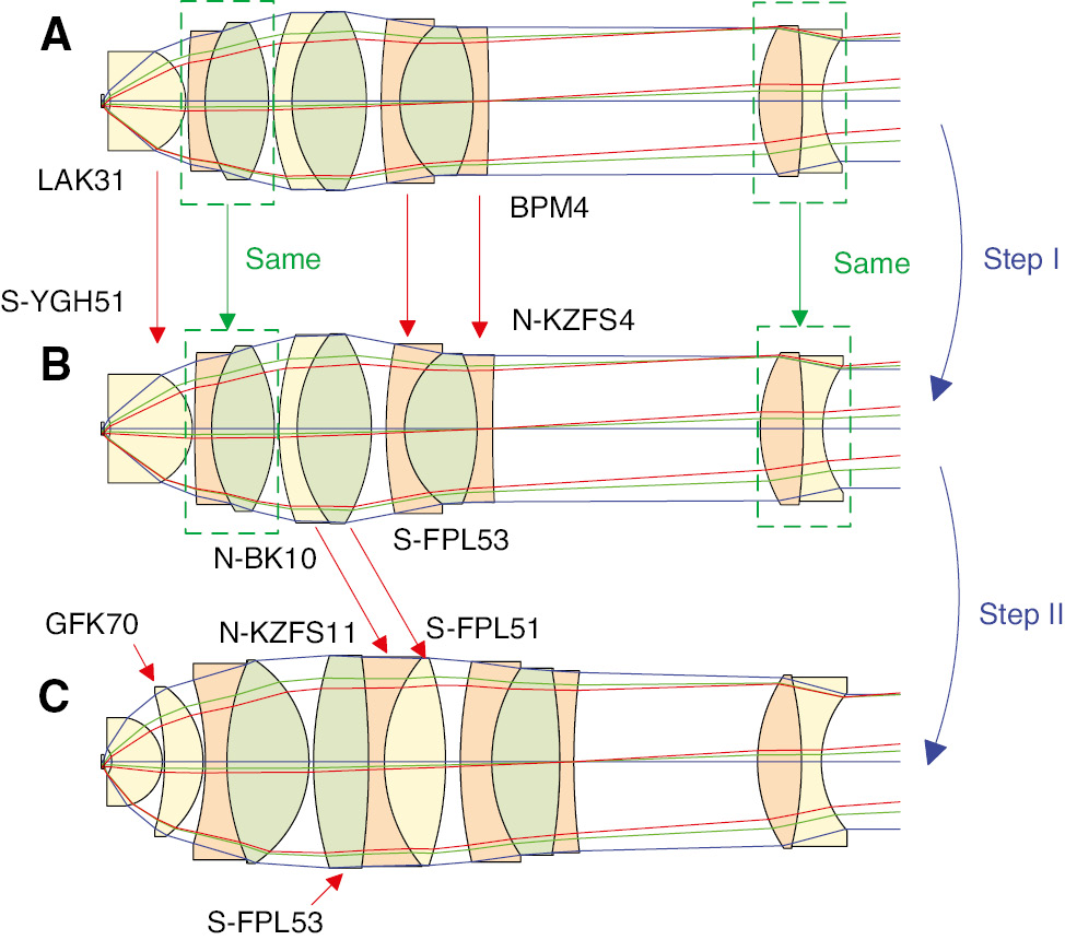
Objective structures and material change during modification. (A) Initial 40×/0.85 objective with g-line to C-line correction. The surface curvatures are slightly adjusted to incorporate the extended spectrum. (B) Step I 40×/0.85 objective with i-line to t-line correction. (C) Step II 40×/0.95 objective with i-line to t-line correction.
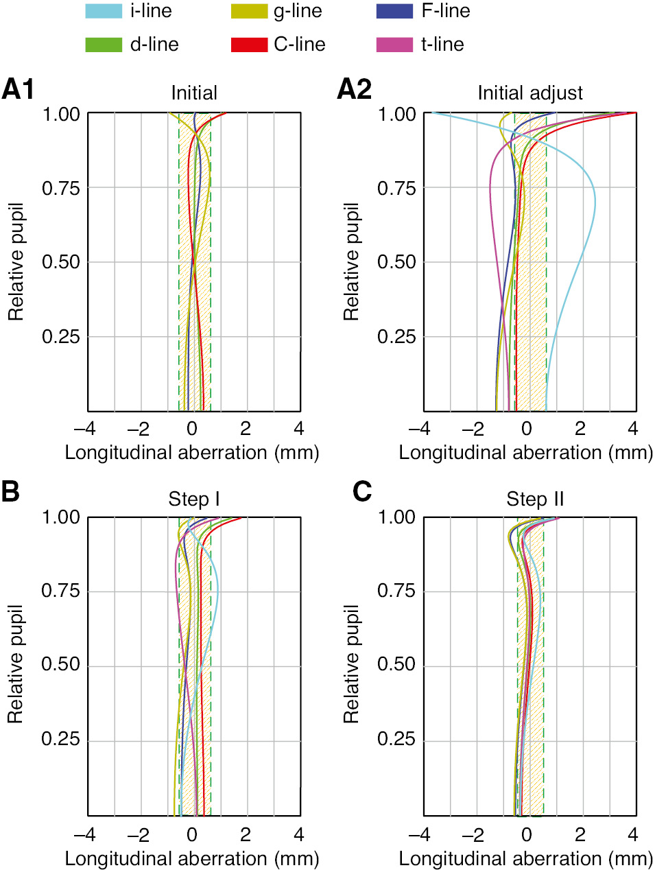
Longitudinal aberration of the initial system and modified systems. The shaded region indicates the DoF of the d-line. (A1) Initial system with g-line to C-line apochromatic correction. (A2) Initial system with slightly adjusted surface curvatures. (B) Step I modified system with i-line to t-line apochromatic correction. (C) Step II modified system with i-line to t-line apochromatic correction and enlarged NA=0.95.
Applications and system parameters of the two-step modification.
| Parameters | Initial | Step I | Step II |
|---|---|---|---|
| Application | Fluo- | Multiphoton | Multiphoton |
| Magnification | 40× | 40× | 40× |
| NA | 0.85 | 0.85 | 0.95 |
| Spectral range | g-C | i-t | i-t |
| Colour correction | Apo-Class (c) | Apo-Class (g) | Apo-Class (g) |
| Field correction | Plan-Class (4) | Plan-Class (4) | Plan-Class (4) |
Before the step I, the surface curvatures of the initial system are first slightly adjusted to incorporate the extended spectrum. ‘Fluo-’ indicates general fluorescence microscopy.
In the first step, the working spectrum of the initial system, which was corrected for general fluorescence microscopy, should be extended from g-C to i-t, covering the spectral range from near ultraviolet (NUV) to near infrared (NIR) for multiphoton microscopy. In the second step, to improve the resolution for more efficient excitation, the NA should be enlarged to 0.95. In the modified systems, correction of the Petzval curvature should be maintained, and the other field aberrations could be corrected by utilising a certain amount of vignetting.
Before applying the new lens modules in the two steps, the surface curvatures were slightly adjusted to incorporate the correction of the i-line and t-line. However, as shown in Figure 20A2 and Figure 21A, although the t-line correction is acceptable, the NUV i-line is out of control and the field correction of the g-line is hampered.
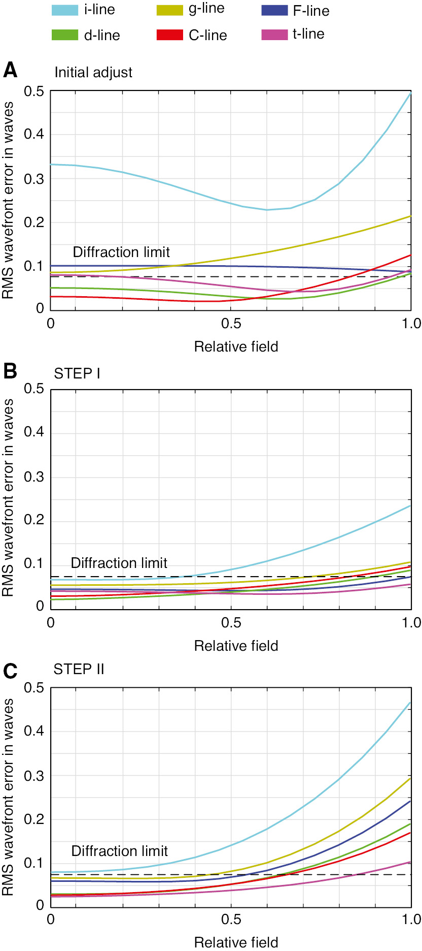
RMS wavefront error of the initial system and modified systems. The dashed line shows the 0.0714 λ diffraction limit given by the Marechal criterion. (A) Initial system with slightly adjusted surface curvatures, corresponding to (A2) in Figure 20. (B) Step I modified system with i-line to t-line apochromatic correction. (C) Step II modified system with i-line to t-line apochromatic correction and enlarged NA=0.95.
In the first step, to keep the ‘P(PN)0’ type (d) optical power distribution, two lens modules are utilised locally in the front and middle groups. To reduce the axial chromatic aberration, which results from the extended working spectrum, and further restrains the spherical aberration, applying the front group lens module no. 6, the ‘Middle Glass’ S-YGH51 (nd=1.755, vd=52.32) is used instead of the LAK31 (nd=1.697, vd=56.42) in the re-optimised front quasi-aplanatic meniscus lens due to its higher refractive index and low dispersion. The material also has low autofluorescence, which is suitable for high-contrast fluorescence imaging. Furthermore, applying middle group lens module no. 1 and no. 2, materials of the two negative components in the cemented triplet in the middle group are changed from BPM4 (nd=1.613, vd=43.84, Pig=1.3229, PCt=0.7875) to N-KZFS4 (nd=1.613, vd=44.49, Pig=1.3015, PCt=0.7933) to achieve better chromatic correction for the UV and IR range. The surface curvatures of the second cemented doublets and the triplet are re-optimised, then creating the longitudinal aberration shown in Figure 20B and RMS wavefront error shown in Figure 21B. Keeping identical the first cemented doublet and the rear lens as the initial system, apochromatic correction is achieved from the i-line to the t-line, and the field performance is also corrected as diffraction limited except the i-line.
In the second step, because of the enlarged NA, a single quasi-aplanatic lens is not sufficient to collect the high NA. Combining the lens module no. 3 and no. 6 of the front group, a GFK70 (nd=1.569, vd=68.37) aplanatic shell lens is inserted behind the front lens. Furthermore, to smoothen the ray path and efficiently collect the high NA, by adopting the lens module no. 5 of the middle group, the shape of the first cemented doublet is changed from bi-convex to meniscus. However, this feature slightly hampers the correction of spherochromatism and axial chromatic aberration. To correct the chromatic aberration and control the zonal error, the second cemented doublet is changed to a cemented triplet (middle group lens module no. 7), which is composed with weak apochromatic cement on the one side (S-FPL53+N-KZFS11) and strong Merte cement (N-KZFS11+S-FPL51) on the other. Consequently, according to Figure 20C, the axial chromatic aberration over the wide spectrum, the spherical aberration including zonal error and the spherochromatism are well corrected for the high NA. However, since we are keeping the single cemented meniscus lens as the rear group, although the field curvature could be corrected, it is hard to control the coma induced by the high NA, resulting in the tremendously increased wavefront error at the boundary field, which could be seen from Figure 21C.
5.2 Synthesis of new structure from basic lens modules
In the second example, the basic lens modules should be used to synthesise a plan-apochromate 40×/1.20 SF20 oil immersion objective with class (c) chromatic correction and class (4) field correction. The system should be corrected for infinity conjugate with 200-mm tube lens, and the parfocal length is fixed as 45 mm. To gradually change the system structure for clear illustration, we set five intermediate steps, which are listed in Table 4. In the synthesis process, the pupil position is always fixed to realise the telecentric object space. Both the spot-radius-based and wavefront-error-based merit functions are used during the synthesis process. Constraints of the element thickness and air spacing are given to assure manufacturability. Certain requirements of longitudinal aberration are also set in the merit function to realise improved zonal spherical aberration and spherochromatism correction.
System parameters of the 40×/1.20 SF20 oil immersion objective with five intermediate steps.
| Parameters | STEP I | STEP II | STEP III | STEP IV | STEP V | Final goal |
|---|---|---|---|---|---|---|
| Magnification | 10× | 40× | 40× | 40× | 40× | 40× |
| NA | 0.25 | 0.60 | 0.85 | 0.85 | 0.85 | 1.20 (oil) |
| Spectral range | F-C | F-C | F-C | g-C | g-C | g-C |
| Colour correction | Ach-Class (a) | Ach-Class (a) | Ach-Class (a) | Fluor-Class (b) | Apo-Class (c) | Apo-Class (c) |
| Field correction | -Class (1) | -Class (1) | -Class (1) | Plan-Class (5) | Plan-Class (5) | Plan-Class (4) |
A simple Petzval structure is calculated to realise the low NA achromate step I system, which is shown in Figure 22A, with its longitudinal aberration in Figure 23A and RMS wavefront error in Figure 24A. A simple crown glass K5 (nd=1.522, vd=59.48) and a flint glass F2 (nd=1.620, vd=36.37) are utilised to form the two positive cemented doublets for axial chromatic aberration. The aperture stop is placed at the back focal plane, achieving the telecentric object space. The small NA, curved image and secondary spectrum are the most critical residual problems.
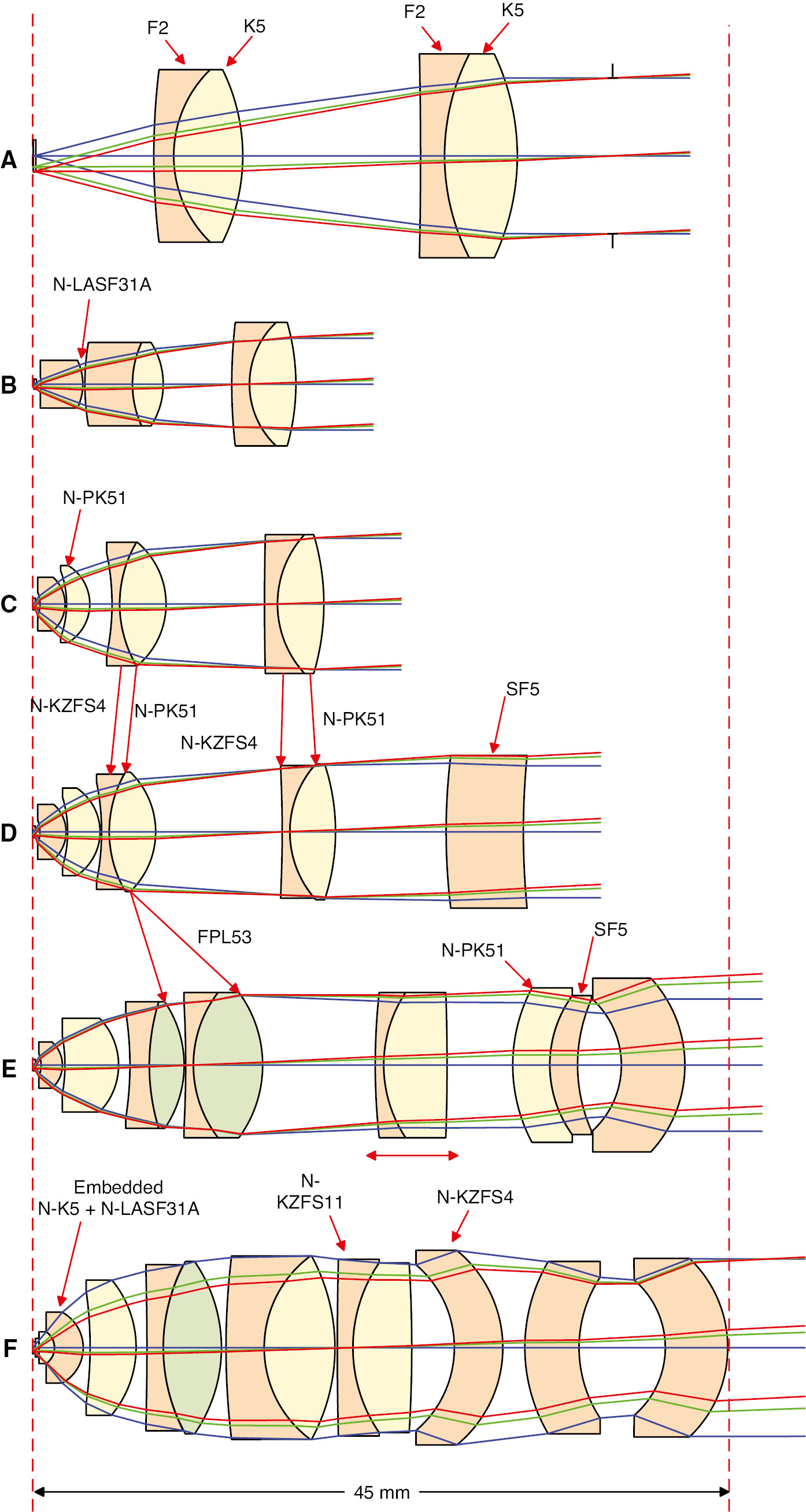
Full process of the 40×/1.20 SF20 oil immersion objective synthesis. (A) Step I 10×/0.25 achromate objective. (B) Step II 40×/0.60 achromate objective. (C) Step III 40×/0.85 achromate objective. (D) Step IV 40×/0.85 plan-fluorite objective. (E) Step V 40×/0.85 plan-apochromate CORR objective. (F) Final design 40×/1.20 plan-apochromate objective.
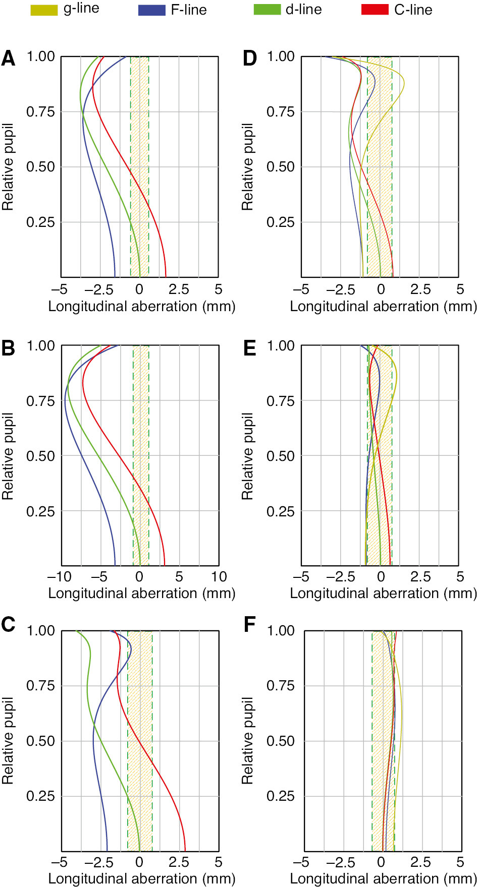
Longitudinal aberration of the final design and synthesised intermediate systems. The shaded region indicates the DoF of the d-line. (A) Step I 10×/0.25 achromate objective. (B) Step II 40×/0.60 achromate objective. (C) Step III 40×/0.85 achromate objective. (D) Step IV 40×/0.85 plan-fluorite objective. (E) Step V 40×/0.85 plan-apochromate CORR objective. (F) Final design 40×/1.20 plan-apochromate objective.
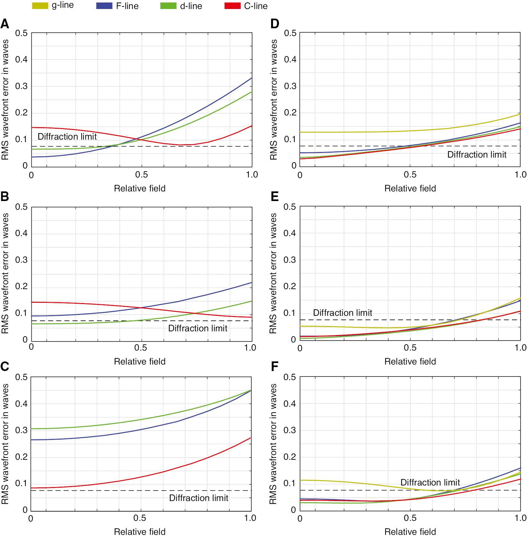
RMS wavefront error of the final design and synthesised intermediate systems. The dashed line shows the 0.0714 λ diffraction limit given by the Marechal criterion. (A) Step I 10×/0.25 achromate objective. (B) Step II 40×/0.60 achromate objective. (C) Step III 40×/0.85 achromate objective. (D) Step IV 40×/0.85 plan-fluorite objective. (E) Step V 40×/0.85 plan-apochromate CORR objective. (F) Final design 40×/1.20 plan-apochromate objective.
In the second step, the NA is first enlarged by applying front group lens module no. 1, no. 4 and no. 5. An Amici lens with curved front surface is used as the front lens of the system in Figure 22B, which is made of the Lanthanum dense flint N-LASF31A (nd=1.883, vd=40.76) glass with high refractive index and medium dispersion. Owing to its high index, the NA is effectively enlarged to 0.60, and the magnification is adapted to 40×. Taking advantage of lens module no. 4, the field curvature of the step II system is not critical. However, the residual secondary spectrum and lateral colour significantly hamper the chromatic performance of the system.
In the third step, the NA is further enlarged to 0.85. To control the induced chromatic aberration and restrain the spherical aberration, aplanatic shell lens made of N-PK51 (nd=1.529, vd=76.98) is inserted behind the front lens, and the shape of the first cemented doublet is changed to meniscus, corresponding to the front group lens module no. 3, no. 6 and middle group lens module no. 5, respectively. According to the Figures 23C and 24C, although the axial chromatic aberration is achromatic corrected for the F-line to the C-line, the residual spherical aberration is large. Furthermore, because of the high NA, the simple ‘two-group’ structure cannot control the coma and astigmatism. As a consequence, the full field performance is far away from being diffraction limited.
Therefore, generating the ‘clear three-group’ structure is necessary to further improve the chromatic correction and field correction. Concerning the medium magnification and high NA, we select the type (c) ‘P(PN)0’ optical power distribution. Corresponding to the rear group lens module no. 1 and no. 6, a thick meniscus lens made of dense flint glass SF5 (nd=1.673, vd=32.21) is used as the rear group, which significantly compensates the field curvature and lateral colour. Furthermore, to correct the high NA spherical aberration including the zonal error and control the secondary spectrum, the simple achromatic class pair K5+F2 is changed to Merte cementing with anomalous dispersive material N-KZFS4+N-PK51 (middle group lens module no. 2 and no. 3). Consequently, according to Figures 23D and 24D, Fluorite-level axial chromatic aberration correction is achieved, but the system suffers from large spherochromatism. The single rear lens cannot fully correct the residual coma; thus, the performance of the boundary field is not diffraction limited.
In the fifth step, the axial chromatic correction is further improved by inserting one more cemented doublet into the middle group and changing the N-PK51 glasses to more anomalous dispersive material FPL53 with strongly curved cementing surface (middle group lens module no. 2). Furthermore, Gauss-type rear group is utilised with its front part cemented by N-PK51 and SF5 (rear group lens module no. 2 and no. 7), which also significantly contributes to the correction of axial chromatic aberration and spherical aberration due to the large marginal ray height. To realise the 0.11–0.19 mm CG CORR function, the type (e) ‘P(P0)N’ optical power distribution is selected and the third cemented doublet with weak optical power is utilised as the moving component. Thereby, as shown in Figures 23E and 24E, the apochromatic-corrected axial chromatic aberration is achieved with well-corrected spherical aberration. The full field performance is nearly diffraction limited.
To reach the final goal of oil immersion (type A oil) objective, regarding the front group lens module no. 8, the embedded front lens with index-matched material should be used instead of the single quasi-aplanatic thick meniscus lens. Therefore, the N-K5 plano-convex small lens is embedded to the N-LASF31A meniscus lens. Furthermore, to control the higher-order spherical aberration to correct zonal spherical aberration, glass pairs of the second and third cemented doublets in the middle group are changed to Merte cementing with N-PK51+N-KZFS11 (middle group lens module no. 3). When it comes to the rear part, separated Petzval-type rear group is used instead of the quasi-symmetric Gauss type (rear group lens module no. 3). The second and third lenses are still made of dense flint glass SF5 for lateral colour correction. However, the first meniscus lens selects anomalous dispersive material N-KZFS4 and forms a reverse-bent structure, which could be used to adjust the higher-order spherical aberration and spherochromatism with its air lens effect. As the final result shown in Figures 23F and 24F, the axial chromatic aberration from the g-line to the C-line is apochromatic corrected with well-controlled zonal error and spherochromatism. However, it is notable that due to the enlarged NA, it is increasingly difficult to correct the coma; therefore, 20% vignetting is introduced to the boundary field to achieve the nearly diffraction-limited field correction.
6 Conclusion
Three important topics about the design principles of modern microscope objectives, which were excluded from Part II, are discussed in this paper. Utilising the special optical power distribution as ‘PNP’ and ‘PPN strong retrofocus’ with additional rear group, the Zone 5 and Zone 6 systems realise very low magnification and very high magnification, respectively. Compared with the Zones 1–4 systems, the application requests and standardised system manufacturing impact more significantly on these two zones. The limited parfocal length and object space telecentricity fix the common structure of the Zone 5 systems, while the high magnification and long WD determine the design of the Zone 6 objectives.
To realise the CORR function, generally three solutions are used in the historical development, which could be further classified into five types. Except for the most traditional method using a removable/replaceable element, the other approaches can be understood as a zooming system with optical compensation or mechanical compensation. Therefore, with respect to the invariance of focal position and chromatic correction together with mechanical complexity, the moving track length, the optical power and the material selection of the moving group should be carefully considered. Air lens effect can also be applied for fine adjustment.
Development of the microscope objectives with DOE significantly depends on the technology of the DOE production. The conventional single-layer DOE can only be used in the quasi-monochromatic applications. Recently, the index-matched bonded-multilayer DOE was developed, which has excellent broadband diffraction efficiency and low cost in mass production. It has been applied to various typical Zones 1–4 objectives, particularly for long WD objectives. In the systems with extremely high NA, apart from the superb potential for colour correction, it shows a similar functionality as asphere for system volume control.
Utilising the building blocks of modern microscope objectives, which are summarised in Part II, as a reverse process, two examples are given in this paper with different considerations of system synthesis. First, as typical system modification for new applications, the lens modules can be inserted locally to the available system by keeping the basic structure and optical power distribution for invariant manufacturing and technology considerations. Second, synthesising the basic lens modules, it is feasible to generate arbitrary new structures for arbitrary applications.
As a conclusion of these three connected papers, based on the large microscope objective database, which is collected from patents over 100 years, the lens modules and design principles used in the modern microscope objectives are well sorted and systematically analysed. By utilising the lens modules, systematic synthesis of new objective structure for new applications is realistic. Nevertheless, although some impacts of some manufacturing and technology requests have been introduced, systematic analysis of sensitivity and tolerance of lens modules is not involved in our work. In future work, for one thing, the lens modules can be connected more closely to the practical manufacturing process with the analysis of their sensitivity behaviour associated with mechanical structure. For another, the lens modules can be described more quantitatively. Thereby, they could be utilised with more general global synthesis algorithm for the automatic design aided by artificial intelligence.
About the authors

Yueqian Zhang did his undergraduate study in Optical Engineering at Zhejiang University, Hangzhou, China. He received his master’s degree in Photonics from Friedrich-Schiller-Universität Jena, Germany, in 2015. Since 2016, he has been working in the Optical Design Group at the Institute of Applied Physics in Friedrich-Schiller-Universität Jena. His research interests are classical system design, microscopic application and system development.

Herbert Gross studied Physics at the University of Stuttgart. He received his PhD on Laser Simulation in 1995. He joined Carl Zeiss in 1982, where he worked as a scientist in optical design, modeling and simulation. From 1995 to 2010, he headed the central department of optical design and simulation. Since 2012, he has been a professor at the University of Jena in the Institute of Applied Physics and holds a chair of Optical System Design. His main working areas are physical optical simulations, beam propagation, partial coherence, classical optical design, aberration theory, system development and metrology. He was the editor and main author of the book series ‘Handbook of Optical Systems.’
References
[1] Y. Zhang and H. Gross, Adv. Opt. Technol. (Part I) 8, 303–337 (2019).Search in Google Scholar
[2] Y. Zhang and H. Gross, Adv. Opt. Technol. (Part II) 8, 339–374 (2019).10.1515/aot-2019-0013Search in Google Scholar
[3] K. Abe, US 9746658 (2016).Search in Google Scholar
[4] D. N. Frolov, J. Opt. Technol. 69, 614 (2002).10.1364/JOT.69.000614Search in Google Scholar
[5] A. Miks and J. Novak, Appl. Opt. 49, 3403–3410 (2010).10.1364/AO.49.003403Search in Google Scholar PubMed
[6] Y. Zhang and H. Gross, Proc. SPIE 10590, 105901G (2017).Search in Google Scholar
[7] D. N. Frolov, O. A. Vinogradova, V. N. Frolov and P. S. Vakulov, Proc. SPIE 10679, 106791G (2018).Search in Google Scholar
[8] H. Gross, Handbook of Optical Systems, Vol. 1: Fundamentals of Technical Optics (Wiley, New York, 2005).10.1002/9783527699223Search in Google Scholar
[9] K. Yamaguchi, JP 2009-294518 (2009).Search in Google Scholar
[10] T. Otaki, T. Inihoshi, M. Sato, H. Haizu and Y. Ouchi, US 6128128 (2000).Search in Google Scholar
[11] W. Klein, US 3176583 (1965).Search in Google Scholar
[12] Y. Ouchi, US 6366398 (1996).Search in Google Scholar
[13] M. Matsubara, US 3925910 (1975).Search in Google Scholar
[14] T. Suzuki, US 5132845 (1990).Search in Google Scholar
[15] K. Arisawa, US 6016226 (2000).Search in Google Scholar
[16] T. Tanaka, US 5555133 (1996).Search in Google Scholar
[17] K. Ushida, US 4403835 (1983).Search in Google Scholar
[18] Y. Shimizu, US 4666256 (1987).Search in Google Scholar
[19] Y. Okuyama, US 20030043473 (2003).10.1088/1126-6708/2003/09/053Search in Google Scholar
[20] R. Shi, US 7349162 (2008).Search in Google Scholar
[21] H. Gross, H. Zügge, M. Peschka and F. Blechinger, Handbook of Optical Systems, Vol. 3: Aberration Theory and Correction of Optical Systems (Wiley, New York, 2007).10.1002/9783527699254Search in Google Scholar
[22] S. Noach, N. P. Eisenberg and Y. S. Arieli, Proc. SPIE 3778 (1999).Search in Google Scholar
[23] Y. Arieli, S. Noach, S. Ozeri and N. Eisenberg, Appl. Opt. 37, 6174–6177 (1998).10.1364/AO.37.006174Search in Google Scholar
[24] T. Tokoyoda, US 2003-0161044 (2003).Search in Google Scholar
[25] A. Imamura, US 5847877 (1998).Search in Google Scholar
[26] K. Suzuki and A. Miyakawa, US 7821715 (2009).Search in Google Scholar
[27] S. M. Ebstein, Opt. Lett. 21 (1996).10.1364/OL.21.001454Search in Google Scholar PubMed
[28] R. Brunner, R. Steiner, K. Rudolf and H. Dobschal, Proc. SPIE 5177 (2003).Search in Google Scholar
[29] R. Brunner, K. Hage, H. Dobschal, K. Rudolf and R. Steiner, US 2004-0174670 (2002).Search in Google Scholar
[30] A. Miyakawa and M. Shijo, US 8367872 (2008).Search in Google Scholar
[31] K. Mukai and M. Yoshida, US 9001420 (2013).Search in Google Scholar
[32] M. Yoshida, US 7848027 (2010).Search in Google Scholar
[33] K. Hiraga, US 6560033 (2002).Search in Google Scholar
[34] K. Yamaguchi, JP 2015-135440 (2015).Search in Google Scholar
[35] M. Yoshida, JP 2011-75982 (2011).Search in Google Scholar
[36] Y. Saito, US 5444573 (1995).Search in Google Scholar
©2019 Yueqian Zhang et al., published by De Gruyter, Berlin/Boston
This work is licensed under the Creative Commons Attribution-NonCommercial-NoDerivatives 4.0 License.
Articles in the same Issue
- Cover and Frontmatter
- Community
- News
- Topical Issue: Systematic design of microscope objectives
- Editorial
- Introduction
- Review Articles
- Systematic design of microscope objectives. Part I: System review and analysis
- Systematic design of microscope objectives. Part II: Lens modules and design principles
- Systematic design of microscope objectives. Part III: miscellaneous design principles and system synthesis