
Nonreciprocal Transmission of Electromagnetic Waves Using an Electric–Gyrotropic Dispersive Medium
-
Guanxia Yu
 ,
Jingjing Fu
,
Jingjing Fu

Abstract
A nonreciprocal transmission structure is designed using a one-dimension multilayer medium, which consists of two asymmetric structure filled with the electric–gyrotropic dispersive media. The total transmission coefficients have been deduced using the transfer matrix method. Numerical results further provided evidence for the occurrence of the nonreciprocal surface electromagnetic waves. These states are affected by the thickness of layers, incident angles, and the externally applied magnetic fields. Given that the electric–gyrotropic media are inherently dispersive, our investigations will contribute to the practical application of nonreciprocal structures.
1 Introduction
In recent investigations, it has been reported that the interaction of surface electromagnetic (EM) waves (SEWs) at an interface yields significant new information relevant to material research, such as the enhanced transmission of light [1], super-resolution imaging [2], biosensing [3], mode converter [4], and so on. A well-known SEW is surface plasmon polaritons (SPPs) [5], [6]. They can be found at the interface between two media with a negative permittivity and a normal media. After the application of a transverse magnetic (TM) excitation wave, these SPPs can be captured and observed using special coupling devices [7] such as prisms and grating couplings. Other familiar types of interface modes include the optical Tamm states (OTSs) [8], [9], [10] that are formed at the interface between two photonic structures with overlapping band gaps. Similar to OTSs, another category of confined EM modes, called Tamm plasmon polaritons, is formed at the boundary between a metal layer and a Bragg mirror [11], [12], [13]. Although the mechanisms vary among the different SEWs, their transmission properties are quite similar at the interface.
One of the novel properties of SEWs is nonreciprocity, which occurs when the structure is in the presence of magneto-optical materials (MOMs) [14], [15], [16], [17], [18]. In MOMs, the nonreciprocity of EM parameters is associated with a break in time reversal symmetry due to an external static magnetic field or spontaneous magnetisation [19], [20]. The nonreciprocity of SPPs was initially observed many years ago, and this phenomenon is currently applied in numerous optical devices. Nevertheless, SPPs only propagate parallel to an interface and decay exponentially in an orthogonal direction away from the surface because they possess an imaginary propagation constant. Therefore, the nonreciprocal behaviour of SPPs is inconspicuous, even if MOMs subjected to an external magnetic field [7]. However, in contrast to SPPs, OTSs are designed to address these limitations using multilayers, and strong nonreciprocal OTSs can be generated via one-way resonant optical tunnelling at the interface between two different magnetic–photonic materials [21], [22]. In particular, an important advantage of OTSs is their low attenuation. Moreover, they can exhibit both TE and TM polarisation [7]. Therefore, when optical elements are designed with functionality that depends on the nonreciprocity of surface waves, OTSs are a viable alternative.
The nonreciprocity of OTSs is determined by the asymmetric gyro-parameters of the MOMs and can be enhanced and optimised by the selection of appropriate asymmetric gyro-parameters [12], [16]. Therefore, the EM parameters of a magneto-optical medium are not fixed and are dependent on the external magnetic field and the frequency of the incident waves [23]. In addition, the propagating properties of nonreciprocal OTSs are influenced by the external magnetic field and the frequency of the incident waves. In this investigation, we consider the asymmetric multilayer composite structure consisting of a dispersive electric–gyrotropic medium. Under the influence of different external magnetic fields and incident frequencies, the different nonreciprocal behaviours can be demonstrated.
In this report, we design an original structure, which is represented by ABAB⋯ABDC⋯DCDC. As shown in Figure 1, the structure is composed of two periodically layered electric–gyrotropic medium, and the dotted line represents their interface. In the cells on the left (AB), A and B are a normal dielectric and a gyrotropic material, respectively. In the cells on the right (DC), C and D are a normal dielectric and a gyrotropic material, respectively. The thickness of layers A, B, C, and D are denoted by d1, d2, d3, and d4, respectively. An external static magnetic field is necessary for the phenomenon of nonreciprocity. The static magnetic fields added to the model at the interface have opposite directions and the same value. The background of the model is air, and the wave vector k(ω) is along the xz plane with an incidence angle (θ).

A simplified schematic description of a mathematical model based on ABAB⋯ABDC⋯DCDC. It consists of two different semi-infinite one-dimensional photonic crystals in which A and C are dielectric media. B and D are gyrotropic materials.
2 Model and Theoretical Analysis
To simplify, we use εrA and εrC to represent the relative permittivities of the isotropic dielectric A and C, respectively. Layers B and D are gyrotropic materials, and their permittivities are εrB and εrD. The gyrotropic layers’ (B and D) dielectric tensors are functions of frequency ω and the external static magnetic field B because of the Voigt geometry and can be expressed as [23]:
with the constitutive parameters defined by
To investigate the nonreciprocal properties, an incident TM mode plane wave in the xz plane (Fig. 1) is assumed. The plane wave can be expressed as
Based on the classical Maxwell equations, the EM fields are continuous at the interface of two adjacent layers (m-layer and n-layer) and can be written as follows:
where Tmn is the transformation matrix of the fields from the m-layer to n-layer, which is defined as
In the transformation matrix,
Then, the full transfer matrix is given by
where N and M represent the periods of the right part and the left part, respectively. Pm and
where dm is thickness of mth layer. In matrix (5), T0m and Tn ′ 0 characterise the transfer matrices for transmission through air to medium m and through medium n′ to air, respectively. Thus, the transmission and reflection of the electric fields can be determined as follows (5):
According to the transfer matrix method, the total transmission coefficient can be calculated as follows:
3 Results and Analysis
In order to demonstrate the nonreciprocity in the designed structure, the transmission properties were numerically calculated for an incident TM mode plane wave travelling from the left boundary of the structure. The structure parameters used in the calculations are as follows: M = 2, N = 3, d1 = 6.5 mm, d2 = 5 mm, d3 = 20 mm, d4 = 22 mm, and an incidence angle of θ = π/6. Layers A and C are normal materials and assume εrA = 2.56 and εrC = 11.5 [24], respectively. For the anisotropy layers B and D, the permittivities depend on (1). In this case, B and D are a kind of dispersive electric–gyrotropic medium and assume n = 8 × 10¹⁷ m−3, ωep = 5.040 × 10¹⁰ s−1, and ωle = ±1.757 × 10¹¹Bs−1 [23], [25], [26]. The value of the external magnetic field was initially set as B = 0.02T. Therefore, according to formula (1), the dispersive and gyrotropic properties of electric–gyrotropic medium are significant in the microwave regime.
Figure 2 shows the transmission coefficients for different incident frequencies, where the solid and dotted lines represent forward and backward waves, respectively. It can be seen that there are four pairs of different nonreciprocal transmission peaks in the range from 4.25 × 10⁸ to 6.7 × 10⁸ Hz at a specific incident angle. It should also be noted that the results are different from the pair of nonreciprocal transmission peaks when fixed EM parameters are used for the nondispersive gyrotropic media [12], [19]. It is more instructive to design multichannel isolators for a specific incident angle in practice. Furthermore, the nonreciprocal frequency intervals and transmission peaks in Figure 2a are larger than those of Figure 2b–d. As such, the forward frequency of 4.2850 × 10⁸ Hz and the backward frequency of 4.2751 × 10⁸ Hz are the desired nonreciprocal frequencies for the proposed structure. Thus, the first pair of peaks was chosen for further investigation.
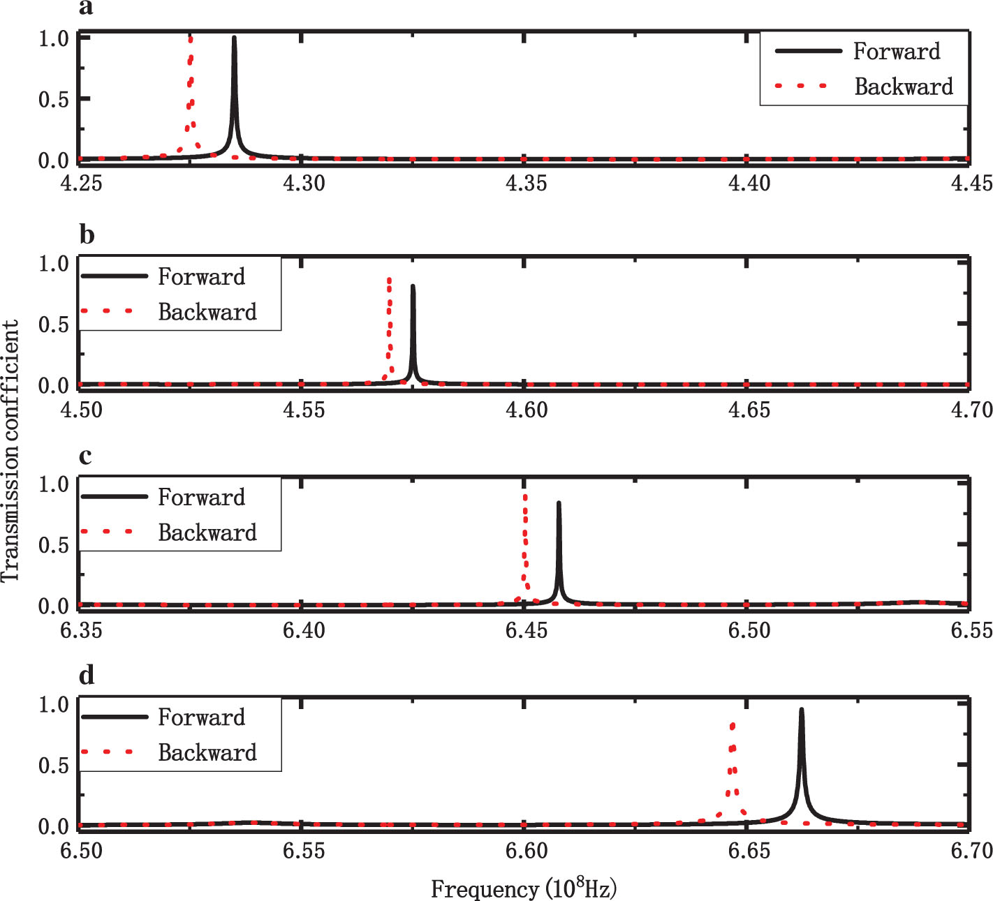
Transmittance of the structure when N = 3 and M = 2.The solid line represents the forward direction, and the dotted line represents the backward direction. (a) Backward 4.2751 × 10⁸ Hz, forward 4.2850 × 10⁸ Hz; (b) backward 4.5698 × 10⁸ Hz, forward 4.5751 × 10⁸ Hz; (c) backward 6.450 × 10⁸ Hz, forward 6.4579 × 10⁸ Hz; (d) backward 6.6468 × 10⁸ Hz, forward 6.6624 × 10⁸ Hz.
To further verify the nonreciprocal properties of Figure 2a, the magnetic field distributions are described in Figure 3 for 4.2850 × 10⁸ and 4.2751 × 10⁸ Hz, respectively. When the wave at 4.2850 × 10⁸ Hz is incident from the left boundary, Figure 3a indicates that the wave propagates completely through the multilayers, which is in accordance with the results shown in Figure 2a. However, the incident wave at the same frequency travelling from the right boundary is totally reflected and forms a standing wave in the incident region (Fig. 3b). Similar results are shown for a frequency of 4.2751 × 10⁸ Hz in Figure 3c and d, where the incident magnetic field from the right boundary is totally transmitted through the multilayers (Fig. 3b). Moreover, the incident magnetic field from the left boundary is totally reflected to form a standing wave in the incident region (Fig. 3d).

The distributions of magnetic fields Hy along xz plane. Same magnetic field values (B = 0.02T) are obtained for two opposite directions for the finite structure. (a) For front illumination, the frequency is 4.2850 × 10⁸ Hz, and the incidence angle is π/6. (b) For back illumination, the frequency is 4.2850 × 10⁸ Hz, and the incidence angle is π/6. (c) For back illumination, the frequency is 4.275 × 10⁸ Hz, and the incidence angle is π/6. (d) For front illumination, the frequency is 4.275 × 10⁸Hz, and the incidence angle is π/6.
The nonreciprocal transmission depends on the nonreciprocal OTSs in the interface, which are influenced by the thickness of the gyrotropic media. The transmission coefficients in the range 4.25 × 10⁸ to 4.45 × 10⁸ Hz for the different thickness values of d1 = 6, 6.5, 7, and 7.5 mm are shown in Figure 4. In this case, the other conditions are the same as those of Figure 2a. It is evident that the nonreciprocal transmission peaks for the forward and backward waves are red-shifted with an increase in the thickness d1. In addition, the separation between the two peaks is stable when the thickness d1 increases.

The relation between the transmission peaks and thickness d1: (a) d1 = 6 mm, (b) d1 = 6.5 mm, (c) d1 = 7 mm, (d) d1 = 7.5 mm.
The angle of incidence also affects the nonreciprocal properties. Figure 5 shows the transmission spectra for different incident angles θ = π/7, π/6, π/5, and π/4, where the other conditions are the same as those of Figure 2a. In Figure 5, it is evident that the frequencies of the nonreciprocal transmission peaks are blue-shifted with an increase in the incidence angle. In addition, the separation between the backward and the forward peaks increases when there is an increase in the angle of incidence, and the nonreciprocality is more pronounced.

The relation between the transmission peaks and the incidence angle θ: (a) θ = π/7, (b) θ = π/6, (c) θ = π/5, (d) θ = π/4.
The asymmetric gyrotropic EM parameters in the layers are a basic condition for nonreciprocity of EM waves, and the external static magnetic field can change and enhance the asymmetry. Hence, the value of the magnetic field is one of the key factors that influence the properties of nonreciprocal propagation. Figure 6 shows the transmission spectra for external magnetic fields B = 0.016T, 0.018T, 0.02T, and 0.022T. The other parameters are the same as those used for the results shown in Figure 2a. As the strength of the external magnetic field is increased, the transmission peaks are blue-shifted, and the separation between the two peaks increases. These results indicate that an increase in the strength of the external magnetic fields can enhance and modulate the properties of the nonreciprocal propagating.

The relation between the transmission peaks and the external magnetic value: (a) B = 0.016T, (b) B = 0.018T, (c) B = 0.02T, (d) B = 0.022T.
In the electric–gyrotropic medium, the dissipation is an intrinsic property due to the collisions of electrons plasma in motion, and the loss effect on the nonreciprocity of EM waves in the electric–gyrotropic layer should be taken into account. Although the loss is relative to the electronic collision frequency, for simplicity, the same fixed loss of the permittivity of the main diagonal element in the electric–gyrotropic medium is considered for the B and D electric–gyrotropic layers. We assume

The relation between the nonreciprocal transmission peaks and the loss in the magneto-optical layers, where the other conditions are the same as those in Figure 2a. (a) γ = 0.0, (b) γ = 0.04, (c) γ = 0.08, (d) γ = 0.12.
4 Conclusions
In this investigation, a nonreciprocal structure (AB)N(DC)M consisting of the electric–gyrotropic dispersive media was designed, and the nonreciprocal properties were investigated. For a specific incident angle, four pairs of different nonreciprocal transmission peaks were observed, which is different from those of a one-dimensional nonreciprocal structure with fixed EM parameters. The theoretical and numerical results show that the nonreciprocal transmission peaks are red-shifted with an increase in the thickness of the electric–gyrotropic dispersive media and blue-shifted with an increase in the angle of incidence and the external magnetic fields. Additionally, the increases in the incident angle and the external magnetic field also enhance the nonreciprocal transmission properties. A tunable and multichannel nonreciprocal structure can be exploited to develop novel nonlinear EM devices such as multichannel EM isolators, EM diode, and so on.
References
[1] W. L. Barnes, W. A. Murray, J. Dintinger, E. Devaux, and T. W. Ebbesen, Phys. Rev. Lett. 92, 107401 (2004).10.1103/PhysRevLett.92.107401Search in Google Scholar PubMed
[2] S. Kawata, Y. Inouye, and P. Verma, Nat. Photon 3, 388 (2009).10.1038/nphoton.2009.111Search in Google Scholar
[3] J. N. Anker, W. P. Hall, O. Lyandres, N. C. Shah, J. Zhao, et al., Nat. Mater. 7, 442 (2008).10.1038/nmat2162Search in Google Scholar PubMed
[4] M. Khatir and N. Granpayeh, IEEE Trans. Magn. 49, 1343 (2013).10.1109/TMAG.2012.2231962Search in Google Scholar
[5] D. K. Gramotnev and S. I. Bozhevolnyi, Nat. Photon. 4, 83 (2010).10.1038/nphoton.2009.282Search in Google Scholar
[6] S. A. Maier and H. A. Atwater, J. Appl. Phys. 98, 011101 (2005).10.1063/1.1951057Search in Google Scholar
[7] H. Raether, Surface Plasmons, Springer, Berlin, Germany 1988.10.1007/BFb0048323Search in Google Scholar
[8] A. V. Kavokin, I. A. Shelykh, and G. Malpuech, Phys. Rev. B 72, 233102 (2005).10.1103/PhysRevB.72.233102Search in Google Scholar
[9] M. Kaliteevski, I. Iorsh, S. Brand, R. A. Abram, J. M. Chamberlain, et al., Phys. Rev. B Condens. Matter 76, 165415 (2007).10.1103/PhysRevB.76.165415Search in Google Scholar
[10] Y. T. Fang, L. K. Chen, J. Zheng, L. Y. Zhou, and J. Zhou, IEEE Photonics J. 6, 4801611 (2014).Search in Google Scholar
[11] A. P. Vinogradov, A. V. Dorofeenko, S. G. Erokhin, M. Inoue, A. A. Lisyansky, et al., Phys. Rev. B 74, 045128 (2006).10.1103/PhysRevB.74.045128Search in Google Scholar
[12] H. Y. Dong, J. Wang, and T. J. Cui, Phys. Rev. B 87, 045406 (2013).10.1103/PhysRevB.87.045406Search in Google Scholar
[13] M. Shukla and R. Das, Opt. Lett. 43, 362 (2018).10.1364/OL.43.000362Search in Google Scholar PubMed
[14] Y. Ruan, R. A. Jarvis, A. V. Rode, S. Madden, and B. L. Davies, Opt. Commun. 252, 39 (2005).10.1016/j.optcom.2005.03.037Search in Google Scholar
[15] V. A. Dmitriev and A. O. Silva, PR Electromagn. Res. Lett. 21, 177 (2011).10.2528/PIERL11011904Search in Google Scholar
[16] Y. T. Fang, Y. X. Ni, H. Q. He, and J. X. Hu, Opt. Commun. 320, 99 (2014).10.1016/j.optcom.2014.01.043Search in Google Scholar
[17] C. He, C. S. Yuan, M. H. Lu, Y. F. Chen, and C. Sun, Opt. Express 21, 28933 (2013).10.1364/OE.21.028933Search in Google Scholar PubMed
[18] H. Lira, Z. Yu, S. Fan, and M. Lipson, Phys. Rev. Lett. 109, 033901 (2012).10.1103/PhysRevLett.109.033901Search in Google Scholar PubMed
[19] A. G. Reza and H. N. Mohiabadi, Eur. Phys. J. D 70, 36 (2016).10.1140/epjd/e2016-60540-0Search in Google Scholar
[20] D. L. Sounas, C. Caloz, and A. Alu, Nat. Commun. 4, 2407 (2013).10.1038/ncomms3407Search in Google Scholar PubMed
[21] A. B. Khanikaev, A. V. Baryshev, M. Inoue, and Y. S. Kivshar, Appl. Phys. Lett. 95, 011101 (2009).10.1063/1.3167356Search in Google Scholar
[22] T. Goto, A. V. Dorofeenko, A. M. Merzlikin, A. V. Baryshev, A. P. Vinogradov, et al., Phys. Rev. Lett. 101, 113902 (2008).10.1103/PhysRevLett.101.113902Search in Google Scholar PubMed
[23] J. A. Kong, Electromagnetic Wave Theory, Wiley-Interscience Publication, New York 1990.Search in Google Scholar
[24] M. Liscidini and J. E. Sipe, J. Opt. Soc. Am. B 26, 279 (2009).10.1364/JOSAB.26.000279Search in Google Scholar
[25] C. Z. Li, S. B. Liu, X. K. Kong, H. F. Zhang, B. R. Bian, et al., IEEE Trans. Plasma Sci. 39, 1969 (2011).10.1109/TPS.2011.2162653Search in Google Scholar
[26] T. W. Cnang, J. R. C. Chine, and C. J. Wu, Appl. Opt. 55, 943 (2016).10.1364/AO.55.000943Search in Google Scholar PubMed
© 2020 Walter de Gruyter GmbH, Berlin/Boston
Articles in the same Issue
- Frontmatter
- Atomic, Molecular & Chemical Physics
- Selection of Single Harmonic Emission Peak for Producing Isolated Attosecond Pulse via Chirped-UV Combined Field
- Dynamical Systems & Nonlinear Phenomena
- Multistability Control of Hysteresis and Parallel Bifurcation Branches through a Linear Augmentation Scheme
- Gravitation & Cosmology
- The Lambert W Function: A Newcomer in the Cosmology Class?
- Hydrodynamics
- New Exact Axisymmetric Solutions to the Navier–Stokes Equations
- Boundary Layer Mechanism of a Two-Phase Nanofluid Subject to Coupled Interface Dynamics of Fluid/Film
- Solid State Physics & Materials Science
- Effect of Irreversible Electrochemical Reaction on Diffusion and Diffusion-Induced Stresses in Spherical Composition–Gradient Electrodes
- Two-Dimensional Hybrid Photonic Crystal With Graded Low-Index Using a Nonuniform Voltage
- Density Functional Study of the Electronic, Elastic and Optical Properties of Bi2O2Te
- Nonreciprocal Transmission of Electromagnetic Waves Using an Electric–Gyrotropic Dispersive Medium
- Erratum
- Erratum to: Quantum-Phase-Field Concept of Matter: Emergent Gravity in the Dynamic Universe